Dual-Frequency SIW Slot Array Antenna for Automotive Radar: configurable FoV, Performance Evaluation, and Tolerance Analysis
Nooshin Feiz
Sadam Hussain Kazimi
Navid Razi
Pedram Ghasemian
Dennis Vollbracht
Markus Clemens
This paper presents a single-layer SIW longitudinal slot array antenna optimized for high gain and low side lobe levels (SLL) in the W-band, designed for LMRR (Long Medium Range Radar) applications. This design enhances detection range at high frequencies. It also provides a wider azimuth field of view (FOV) at lower frequencies. The approach improves compactness and reduces costs. It eliminates the need for multiple antennas in different radar ranges. The system includes two band pass filters (BPFs) and one power divider. These components integrate into four antenna arrays, each with six slots. The results show a 4.6 dB gain improvement between lower and higher frequency bands. The antenna extends the maximum detection range by 168 m for a vehicle with an RCS of 10 dBsm in a lossless system. Additionally, the study analyses the normalized admittance of the antenna. It examines the effects of slot length, width, and displacement on conductance and susceptance. These findings confirm the antenna's efficiency for radar applications. A comprehensive tolerance analysis was performed to assess the proposed design's robustness under variations in key parameters.
- Article
(2963 KB) - Full-text XML
- BibTeX
- EndNote
Automotive radar technology has better performance than other technologies like LiDAR, ultrasound, and far-infrared cameras in challenging conditions such as poor lighting, adverse weather, and extreme temperatures (Aqlan et al., 2016; Bloecher et al., 2009; Rabinovich et al., 2010). Automotive radar technology has proven to be effective. Radar antennas are generally classified based on their detection range into three types: short-range radar (SRR), medium-range radar (MRR), and long-range radar (LRR) (Bakhshi et al., 2024; Pandey, 2019; Rabinovich et al., 2010). SRR have a wider field of view (FoV) and lower maximum gain. They are mainly used for near-distance applications like parking assistance, blind spot detection, lane change assistance, and obstacle detection. In comparison with SRR, LRR antennas have narrower FoV and higher gain and detection range. They are used in applications like highway cruise control, autonomous driving, and early collision detection. These systems present data about objects at long distances. So, it provides more time for decisions like slowing down. MRR is between LRR and SRR category. It has higher gain than SRR and wider FoV than LRR. They are often used for applications like adaptive cruise control (ACC), and collision warning systems (Kannappan et al., 2022; Michel et al., 2022; Woo, 2022; Yacoub and Aloi, 2022). The microstrip antenna is traditionally utilized in automotive radar systems because it is simple to manufacture and integrate with microwave circuits. Nevertheless, it suffers from several limitations, including radiation loss, dielectric loss, high element mutual coupling in an antenna array configuration , and inadequate Side Lobe Level (SLL) performance. In contrast, the Substrate Integrated Waveguide (SIW) has gained attention as a promising technology for millimeter-wave (mmW) antenna arrays. SIW provides several benefits, such as a high-quality factor, minimal radiation loss, straight forward production, and seamless integration with other components. Additionally, the spacing between adjacent SIW slots can be designed half a wavelength, in contrast to the one-wavelength spacing between patches in microstrip antennas. This difference allows for a greater number of radiation elements to be incorporated within the same physical area (Huang et al., 2015; Liao et al., 2021; Martinez-Ros et al., 2013; Yang et al., 2015). In this paper, a design of a novel single-layer SIW slot array antenna tailored for radar applications is presented, operating within the 76–81 GHz bandwidth. In order to enhance performance across medium and long distances, both MRR and LRR functionalities (LMRR) are combined into a single radar antenna in two different frequencies. Higher frequency band, with shorter wavelengths, provides high gain and high range resolution, allowing the radar to detect weak signals and distinguish between closely spaced objects with precision. This is ideal for applications requiring detailed imaging. In contrast, lower frequency band, with longer wavelengths, offer a wider field of view (FOV), enabling the radar to cover a broader area of perception, which is useful for surveillance and general monitoring purposes. Section 2 explains the design procedure for the filter and power divider. These components are designed to meet the given specifications. Section 3 investigates normalized admittance of longitudinal slot antenna in SIW technology. It also examines the effects of slot length, width, and displacement on normalized conductance and susceptance. Section 4 focuses on antenna design. It presents the design methodology, including the parameters used to achieve the desired performance. The results obtained from the antenna are also discussed. Section 5 presents the maximum radar range calculation. Finally, Sect. 6 discusses tolerance investigations. It evaluates the effects of via movement and slot dimension variation on overall antenna performance.
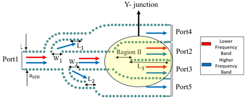
To achieve a gain difference of more than 3 dB between 76.5 and 79 GHz, a specialized SIW frequency selective filter is first designed. In order to activate different sections of the antenna array based on the operating frequency band, the SIW filter is designed. At the lower frequency band, only two antenna elements, positioned centrally within the structure, are activated. At the higher frequency band, all antenna arrays are activated to provide the desired radiation pattern. The structure in SIW design is implemented on a Rogers 3003 dielectric substrate, which has a relative permittivity (εr) of 2.94 and a thickness of 0.508 mm. The thickness of metal layer on both sides of the substrate is of 0.0508 mm. The periodicity and via diameter are carefully chosen to have a balance between fabrication limits and electromagnetic performance. In order to meet fabrication specifications, the diameter of the vias (d) in our SIW design is set to 0.25 mm. To minimize radiation loss, the periodicity between the vias (s) is set to 0.4 mm. By considering the optimal spacing, the possibility of leakage between the vias is decreased. So, electromagnetic waves can propagate in the structure with minimum loss. The width of the rectangular waveguide is defined by (a). Figure 1 illustrates the structure of the SIW filter and power divider. The figure provides a clear visual representation of the electromagnetic power distribution for both the lower and higher frequency bands. The red arrows in the figure indicate the path that electromagnetic waves in the lower frequency band approach toward the output ports (port 2 and 3). The blue arrows represent the signal flow at the higher frequency band. So, the paths for lower and higher frequencies are clearly differentiated. The proposed design incorporates several key features: 1. Two band pass filters (BPFs): Two SIW filters with a resonance frequency of 76.5 GHz are designed. These filters are optimized to selectively pass signals in the higher frequency band to Port 4 and Port 5. The extracted pole technique is utilized for designing the filter. When electromagnetic energy is coupled into the resonators at the resonant frequencies of the band-stop cavities, strong cancellation is occurred. In other words, by creating transmission zeros, the lower frequency band is effectively suppressed and the higher frequency band is passed through the filter (Chen et al., 2005). In order to design the BPF in SIW structure, the width and the length of the filter must be calculated. The filter's performance, like its passband frequency, impedance matching, and overall frequency response, is affected by filter dimensions. The width and length of filter is calculated following Eqs. (1) and (2), respectively (Chen et al., 2005).
The resonant frequency of a SIW filter is determined by Eq. (3)
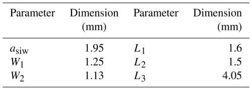
2. Filter Entrance Offset: An intentional offset is introduced between the entrances of the filters. The control of reflection waves across the four signal paths and preventing phase cancellation are the reasons for using filter entrance offset. By calculating and optimizing the length and width of BPF, impedance matching, minimal insertion loss, and strong out-of-band rejection are achievable. The Y-junction power divider (PD) is positioned at the center of the structure to distribute electromagnetic energy to the central port equally. Like in BPFs, the swept-arc bend in a power divider is designed to maintain impedance matching in Region II of PD. All design values are given in Table 1.
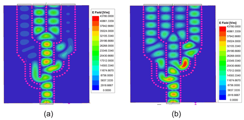
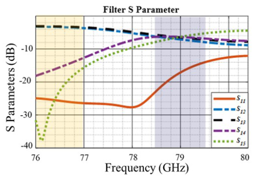
Figure 2 illustrates the electric field distribution of the proposed frequency selective filter at two distinct frequencies: (a) 76.5 and (b) 79 GHz. At 76.5 GHz, the electric field distribution indicates that, because of using the BPF, the majority of the power is directed towards the central output ports. PD provides the equal division of electromagnetic power. At the higher frequency band, the electromagnetic power is divided equally across all the output ports. This equal division ensures that connected antennas receive the same amount of power. Figure 3 illustrates the S-parameters of the proposed SIW frequency selective filter and power divider. From this figure, the performance across a range of frequencies is observed.
Lower Frequency: At lower frequencies, the S-parameters show that the electromagnetic power is received by Port 2 and Port 3 equally. While, Port 4 and Port 5 receive only −18 and −24 dB, respectively. So it indicates negligible power is reached to port 4 and 5. Higher Frequency: power is equally distributed among all four output ports. This demonstrates a balanced distribution of the electromagnetic energy across all output ports.
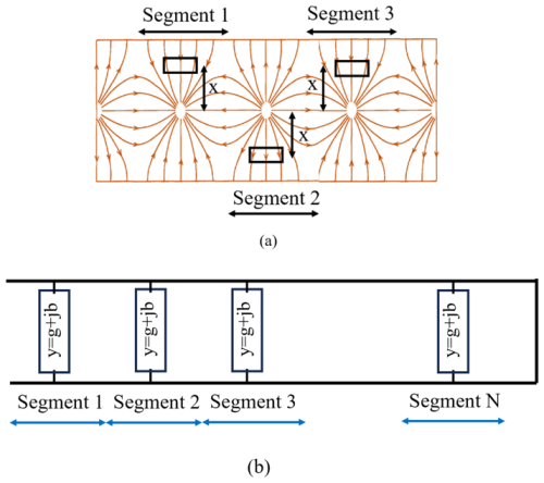
A slot array can be considered as a segment. Each segment has one slot that can be modeled as a shunt circuit configuration. They are characterized in terms of their admittance on a transmission line with a specified characteristic conductance (Elliott, 1983). The normalized admittance of this two-port model is determined based on the precise dimensions of each slot. The admittance calculation is crucial because it controls the input impedance matching and overall radiation pattern of the antenna structure. Equation (4) represents the relation between the normalized admittance (G0) and the S-parameters (Elliott, 1983).
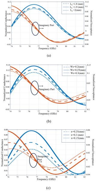
Figure 5Conductance and susceptance analysis of a single slot configuration with variations in (a) the slot length (b) slot width (c) displacement.
In this analysis, Gelement and Belement represent the conductance and susceptance of the radiating element, respectively. The reflection coefficient of the single slot is shown by S11_element. This section focuses on calculating the normalized conductance and susceptance for a single slot in SIW configuration.
Figure 4 represents the longitudinal slot configuration and its equivalent circuit. Figure 5 shows the normalized conductance and susceptance for variation in length, width and displacement of slot.
As shown in Fig. 5a, small adjustments to the slot length result in minimal changes to the conductance, susceptance, and overall admittance. This stability occurs because once the slot reaches its resonant frequency, it effectively acts as a resonant structure. Consequently, further small changes in length do not significantly impact the admittance.
In Fig. 5b, it is shown that varying the slot width has a minimal effect on the overall admittance. In order to explain the reason, it should be noted that it is assumed only dominant mode exists in slot configuration. Therefore, the admittance is largely dependent on the length rather than the width. In contrast, Fig. 5c demonstrates that changing the displacement of the slot has a significant effect on conductance and susceptance. Adjusting the slot's position affects the alignment and distribution of the current flow along the slot. So it can change the admittance significantly. By varying the displacement, the phase and amplitude of the current distribution are varying.
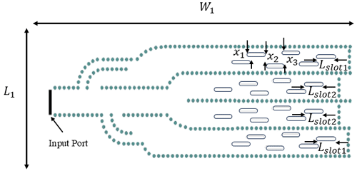
The configuration of the proposed SIW slot array antenna, with the frequency selective filter design, is depicted in Fig. 6. The antenna consists of four linear arrays, each containing six slots. The width of each slot is precisely 0.5 mm. In this design, the Dolph-Chebyshev taper was implemented by controlling the offset of each slot from the waveguide centre line to achieve a specified amplitude distribution across the array. The tapering coefficients were calculated based on a Chebyshev polynomial synthesis approach, which enables systematic sidelobe level control by setting a desired SLL. Each slot's offset was then adjusted accordingly to realize the desired amplitude distribution, ensuring that the radiated field closely matches the target pattern with low sidelobes.
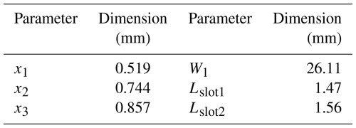
The dimension of proposed SIW antenna are given in Table 2.
Due to the use of the proposed filter, antennas are working in two different frequency bands. The center antenna operates in the lower frequency band. Therefore, it provides lower gain and wider FoV, which is crucial for detecting objects over a medium range. All antennas are operating at a higher frequency band. So, it has a higher gain and detection range. This dual-frequency functionality allows the antenna system to seamlessly transition between medium-range and long-range radar tasks, depending on the operational requirements. As a result, the proposed antenna system can be classified as an LMRR classification.
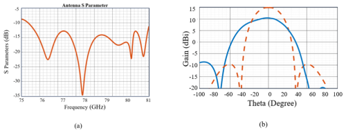
Figure 7a illustrates the reflection coefficient of the proposed SIW slot array antenna. It is obvious that the antenna has excellent bandwidth performance. The antenna achieves a broad operational bandwidth. It covers the fully automotive radar frequency range from 76 to 81 GHz. This broad bandwidth is critical to have a minimum insertion loss and efficient electromagnetic power transmission. Figure 7b presents the E-plane radiation pattern of the antenna at two specific frequencies: 76.5 and 79 GHz. At 76.5 GHz, the antenna exhibits a maximum gain of 10.3 dBi, while at 79 GHz, the gain increases significantly to 14.93 dBi. This results in a gain difference of 4.63 dBi between the two frequency bands.
The proposed antenna design offers a significant advantage with its configurable FOV and gain using dual-frequency operation. Using radar range Eq. (5) (Richards, 2014), the maximum range (Rmax) of the radar is calculated considering the assume parameters such as transmit power (Ptx), antenna transmit gain (Gtx), antenna receive gain (Grx), signal-to-noise ratio (SNR), and target RCS (σ) (Feiz et al., 2024; Kazimi et al., 2024).
At 76.5 GHz, the antenna achieves a realized gain of 10.3 dBi which results in a maximum detection range of 250.41 m for a vehicle with a RCS of 10 dBsm. When switching to the 79 GHz frequency, the gain increases to 14.9 dBi. Under the same conditions, this higher gain extends the maximum detection range to 418.48 m. This substantial increase in detection range demonstrates the enhanced performance and flexibility of the proposed antenna design, making it highly effective for automotive Adaptive Cruise Control (ACC) and Automated Emergency Braking (AEB) in long range applications.
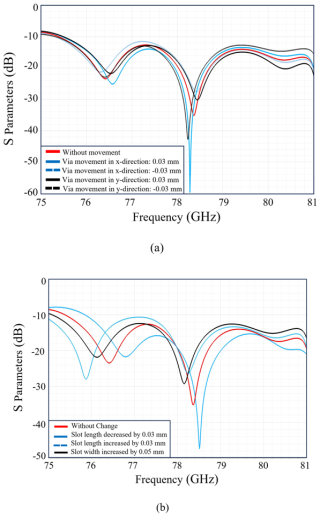
To evaluate the robustness of the proposed design, a comprehensive tolerance investigation was conducted. This analysis focuses on the antenna's performance when key design parameters are varied. The study examines the effects of slight shifts in via positioning along both the x and y axes and changes in slot length and width. Figure 8 shows the tolerance investigation for different parameters. The radiation pattern of the two center frequencies (76.5 and 79 GHz) remains constant across different tolerance investigations. In the worst-case scenario, it changes by a maximum of 0.5 dB. Therefore, the analysis focuses only on the reflection coefficient. The tolerance investigation depicted in Fig. 8a focuses on the displacement of vias along the x-axis. In this movement, vias are moved upward and downward. In this analysis, only the vias are displaced, while other components, such as slots, remain stationary. A tolerance range of ±30 µm is applied. It demonstrates that bandwidth remains relatively unaffected. Additionally, tolerance for displacement of vias along the y-axis is shown in this figure. In this case, vias move to right and left. The same tolerance range of ±30 µm is applied. Only the vias are displaced while slots remain in fixed positions. This increased stability is due to the fact that y-axis displacement does not change the distance between vias and slots. Therefore, it shows more stability than via x-axis displacement. Figure 8b presents the reflection coefficient response resulting from changes in the length and width of the slots. The slot length is varied within a tolerance range of ±30 µm. It is observed that over entire bandwidth (76–81 GHz) the antenna performance remains unaffected by these variations in slot length. However, slight frequency shifts are observed. Additionally, Fig. 8b includes the effects of slot width variations. Analysis shows that the reflection coefficient remains stable despite changes in slot width. This stability is explained that variations in width do not significantly impact the normalized admittance. Thus, the reflection coefficient remains robust against slot width change. It is important to note that all investigation parameters are considered independently. This means that moving vias in the x and y directions is performed separately.
The successful design and analysis of a single-layer SIW longitudinal slot array antenna has been presented, which was specifically optimized for high gain and low SLL in the W band. The design combines MRR and LRR functionalities into a new dual-frequency antenna .Thus, it offers compactness and cost efficiency. The proposed configuration has two BPFs, a power divider and four antenna arrays, each consisting of six slots. The implementation of the Dolph-Chebyshev tapering was proven to be effective in enhancing the sidelobe performance. Additionally, the antenna demonstrated an overall gain improvement of 4.6 dB, validating the proposed design's effectiveness and showcasing its suitability for automotive radar applications. The maximum automotive radar detection range has been increased by 168 m for considering a vehicle as a target RCS of 10 dBsm. The design offers a high gain that provides excellent detection range at higher frequency band and a wider azimuth FOV at lower frequency band. Additionally, the investigation study of the normalized admittance of the longitudinal slot antenna has been shown. It examines the effects of slot length, width, and displacement on normalized conductance and susceptance. These investigations complement the design process. It provides a comprehensive understanding of the antenna's behaviour and enhancing its overall functionality. A detailed tolerance investigation was conducted to assess the robustness of the proposed design. The analysis evaluates the antenna's performance under variations in key design parameters.
The code used for electromagnetic simulations and analysis in this study is not publicly accessible, as it was developed within a collaborative research project between APTIV and the University of Wuppertal. The tools used include CST Studio Suite and MATLAB, both of which are commercial software packages.
The simulation data supporting this study are available from the corresponding author upon reasonable request. The data are not deposited in public repositories due to company confidentiality restrictions under APTIV's research agreement.
NF designed the antenna, filter, and power divider, and carried out all related simulations and analysis. She also led the preparation of the manuscript. SHK supported the implementation of the maximum radar range calculation. NR and PG contributed to the literature review. DV and MC supervised the research and provided guidance on the antenna design. All authors reviewed the manuscript and contributed to its final version.
The contact author has declared that none of the authors has any competing interests.
Publisher’s note: Copernicus Publications remains neutral with regard to jurisdictional claims made in the text, published maps, institutional affiliations, or any other geographical representation in this paper. While Copernicus Publications makes every effort to include appropriate place names, the final responsibility lies with the authors.
This article is part of the special issue “Kleinheubacher Berichte 2024”. It is a result of the Kleinheubacher Tagung 2024, Miltenberg, Germany, 24–26 September 2024.
This work was supported under the to APTIV Services Deutschland GmbH and Bergische Universität Wuppertal for the their joint research grant, which supported this research.
This research was supported by APTIV Services Deutschland GmbH and Bergische Universität Wuppertal under their joint research collaboration grant.
This paper was edited by Simon Adrian and reviewed by two anonymous referees.
Aqlan, B., Vettikalladi, H., and Alkanhal, M. A. S.: High gain SIW-based antenna with superstrate for automotive radar applications, in: 2016 Loughborough Antennas & Propagation Conference (LAPC), 2016 Loughborough Antennas & Propagation Conference (LAPC), Loughborough, Leicestershire, UK, 14–15 November 2016, 1–5, https://doi.org/10.1109/LAPC.2016.7807553, 2016.
Bakhshi, M., Ayatollahi, S. H., and Akbari, M.: Enhancing long-range radar (LRR) automotive applications: Utilizing metasurface structures to improve the performance of K-band Longitudinal Slot Array Antennas, AEU – International Journal of Electronics and Communications, 176, 155134, https://doi.org/10.1016/j.aeue.2024.155134, 2024.
Bloecher, H.-L., Sailer, A., Rollmann, G., and Dickmann, J.: 79 GHz UWB automotive short range radar – Spectrum allocation and technology trends, Adv. Radio Sci., 7, 61–65, https://doi.org/10.5194/ars-7-61-2009, 2009.
Chen, X., Hong, W., Zhangcheng Hao, and Wu, K.: Substrate integrated waveguide quasi-elliptic filter using extracted-pole technique, in: 2005 Asia-Pacific Microwave Conference Proceedings, 2005 Asia-Pacific Microwave Conference, Suzhou, China, 4–7 December 2005, 3 pp., https://doi.org/10.1109/APMC.2005.1606318, 2005.
Elliott, R.: An improved design procedure for small arrays of shunt slots, IEEE T. Antenn. Propag., 31, 48–53, https://doi.org/10.1109/TAP.1983.1143002, 1983.
Feiz, N., Kazimi, S. H., Razi, N., Ghasemian, P., Vollbracht, D., and Clemens, M.: Dual Frequency SIW Longitudinal Slot Array Antenna for Automotive Radar Application: Configurable FOV and Gain, in: 2024 Kleinheubach Conference, 2024 Kleinheubach Conference, Miltenberg, Germany, 24–26 September 2024, 1–4, https://doi.org/10.23919/IEEECONF64570.2024.10739075, 2024.
Huang, G.-L., Zhou, S.-G., Chio, T.-H., Hui, H.-T., and Yeo, T.-S.: A Low Profile and Low Sidelobe Wideband Slot Antenna Array Feb by an Amplitude-Tapering Waveguide Feed-Network, IEEE T. Antenn. Propag., 63, 419–423, https://doi.org/10.1109/TAP.2014.2365238, 2015.
Islamov, I.: Modeling of Microwave Waveguide Systems of Complex Structure in Nonlinear Media in a Mobile Computer System, in: Radio Engineering and Telecommunications Waveguide Systems in the Microwave Range, Springer Nature Switzerland, Cham, 99–140, https://doi.org/10.1007/978-3-031-37916-1_3, 2024.
Kannappan, L., Palaniswamy, S. K., Kanagasabai, M., Kumar, P., Alsath, M. G. N., Kumar, S., Rao, T. R., Marey, M., Aggarwal, A., and Pakkathillam, J. K.: 3-D twelve-port multi-service diversity antenna for automotive communications, Sci. Rep., 12, 403, https://doi.org/10.1038/s41598-021-04318-0, 2022.
Kazimi, S. H., Vollbracht, D., Varma, S., and Chandra, M.: Dual Linearly Polarized 76-81 GHz Automotive Antenna System Concept for Street Condition Monitoring, in: 2024 Kleinheubach Conference, 2024 Kleinheubach Conference, Miltenberg, Germany, 24–26 September 2024, 1–4, https://doi.org/10.23919/IEEECONF64570.2024.10739226, 2024.
Liao, X., Jiang, X., Zhu, X.-L., Peng, L., Wang, K.-F., Wang, J.-H., and Huang, L.-M.: Substrate integrated waveguide slot array antenna for 77 ghz automotive angular radar applications, PIER C, 112, 153–164, https://doi.org/10.2528/PIERC21032404, 2021.
Martinez-Ros, A. J., Gomez-Tornero, J. L., and Goussetis, G.: Holographic Pattern Synthesis With Modulated Substrate Integrated Waveguide Line-Source Leaky-Wave Antennas, IEEE T. Antenn. Propag., 61, 3466–3474, https://doi.org/10.1109/TAP.2013.2257650, 2013.
Michel, A., Singh, R. K., and Nepa, P.: A Compact and Wideband Dashboard Antenna for Vehicular LTE/5G Wireless Communications, Electronics, 11, 1923, https://doi.org/10.3390/electronics11131923, 2022.
Pandey, A.: Practical microstrip and printed antenna design, Artech House, Norwood, MA, 415 pp., ISBN 978-1-63081-668-1, 2019.
Rabinovich, V., Alexandrov, N., and Alkhateeb, B.: Automotive antenna design and applications, CRC Press/Taylor & Francis, Boca Raton, FL, 312 pp., https://doi.org/10.1201/9781439804094, 2010.
Richards, M. A.: Fundamentals of Radar Signal Processing, 2nd edn., McGraw-Hill Education, New York, ISBN 9780071798327, 2014.
Woo, D. S.: A triple band c-shape monopole antenna for vehicle communication application, PIER C, 121, 97–106, https://doi.org/10.2528/PIERC22060202, 2022.
Yacoub, A. and Aloi, D. N.: Low-Profile Automotive Antenna Systems for MIMO 5G and L1/L5 GNSS Communications, in: 2022 16th European Conference on Antennas and Propagation (EuCAP), 2022 16th European Conference on Antennas and Propagation (EuCAP), Madrid, Spain, 27 March–1 April 2022, 1–4, https://doi.org/10.23919/EuCAP53622.2022.9769623, 2022.
Yang, H., Montisci, G., Jin, Z., Liu, Y., He, X., and Mazzarella, G.: Improved Design of Low Sidelobe Substrate Integrated Waveguide Longitudinal Slot Array, Antennas Wirel. Propag. Lett., 14, 237–240, https://doi.org/10.1109/LAWP.2014.2360832, 2015.
- Abstract
- Introduction
- SIW Frequency Selective Filter and Power Divider Design
- Investigation on Longitudinal Slot Array Antenna
- SIW Slot Array Antenna
- Maximum Radar Range Calculation
- Tolerance Investigation
- Conclusions
- Code availability
- Data availability
- Author contributions
- Competing interests
- Disclaimer
- Special issue statement
- Acknowledgements
- Financial support
- Review statement
- References
Automotive radar systems help vehicles detect objects and improve safety. This research presents a new antenna design that operates at two different frequencies to enhance both detection range and field of view. The design improves radar performance while keeping the system compact and cost-effective. By carefully analyzing the antenna, its reliability is confirmed. This innovation can support advanced driver assistance systems, making future vehicles safer and more efficient.
Automotive radar systems help vehicles detect objects and improve safety. This research presents...
- Abstract
- Introduction
- SIW Frequency Selective Filter and Power Divider Design
- Investigation on Longitudinal Slot Array Antenna
- SIW Slot Array Antenna
- Maximum Radar Range Calculation
- Tolerance Investigation
- Conclusions
- Code availability
- Data availability
- Author contributions
- Competing interests
- Disclaimer
- Special issue statement
- Acknowledgements
- Financial support
- Review statement
- References


