Backscattering-Based Radiation Mode Analysis for Angle Estimation of a CRLH Leaky Wave Antenna
Jeleel Alao Oladapo
Simon B. Adrian
Mark A. Eberspächer
This study explores the extraction of the radiation mode field from backscattering field components of a composite right/left-handed (CRLH) leaky wave antenna (LWA) to estimate the relative angle to the radiation mode field within its frequency band of operation. Two methods, transmission line delay (TLD) and impedance loading (IL), for extracting the radiation mode from backscattering field components, are employed to isolate the radiation mode field of a CRLH LWA. In the IL method, backscattered fields are measured by terminating the CRLH LWA with short and open load impedances to express the radiation mode and structure mode field components. The TLD method uses a coaxial transmission line to connect the CRLH LWA to a high-gain X-band horn antenna, enabling isolation of the radiation mode field component from the backscattered field components, using time gating. This analysis employs two measurement setups for TLD, one in which both the CRLH LWA and the horn antenna rotate along the azimuth and the other in which only the CRLH LWA rotates. The analysis shows the frequency-angle relationship of the CRLH LWA radiation mode field, which reveals the frequency-dependent features of the CRLH LWA. Additionally, an evaluation of frequency ambiguity is done to provide more insights into the effectiveness of each approach for angle estimation of CRLH LWA relative to the incident wave.
- Article
(2347 KB) - Full-text XML
- BibTeX
- EndNote
A leaky wave antenna (LWA) is a type of travelling wave antenna that radiates electromagnetic waves along its length, gradually leaking energy to produce a highly directed radiation pattern (Johnson and Jasik, 1993). LWAs are particularly effective in frequency-based beam scanning applications. These antennas perform frequency scanning in a single sweep without mechanical tuning, unlike phased array antennas that require complex mechanical devices or active electronic components for antenna beam control. Mechanical beam scanning usually requires complex control structures, and electronic beam scanning mechanisms are generally lossy, and the amount of loss depends on the characteristics of the components at higher frequencies. Since their development, there has been a significant increase in the use of LWAs, such as in 5G networks (Karmokar and Guo, 2017). Microstrip leaky wave antennas (LWAs) have gained significant attention due to their planar structure, cost-effectiveness, and ease of integration (Caloz and Itoh, 2005). Unlike traditional LWAs, which use waveguides or dielectric slabs, microstrip LWAs can be fabricated using standard printed circuit board (PCB) technology, making them compact, lightweight, and low-cost (Saeed et al., 2024). Their planar nature allows for seamless integration with other microwave and millimeter-wave components, enabling their use in advanced communication and radar systems (Xu et al., 2010). They are used in various fields, including human tracking, automotive radars, imaging, MIMO systems, and low-cost radars for object detection and navigation (Suliman Munawar, 2020; Yang and Ling, 2013).
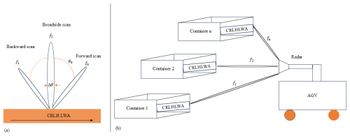
Figure 1Frequency scanning of a CRLH LWA (a) and scanning capability illustration with an AGV-mounted radar system (b).
A promising yet underexplored application of LWAs is in autonomous ground vehicle (AGV) navigation, where they can be used to realize low-cost passive radar tags with frequency-selective radar cross-section (RCS).
In an automated warehouse, passive radar tags can be affixed to containers, enabling AGVs to determine the correct approach angle for precise positioning and alignment. By leveraging the natural frequency-scanning properties of LWAs, a single-channel radar system could estimate the relative angle to the tag based on the received frequency response of the radiation mode field of the tag, as illustrated in Fig. 1b. While this concept presents a promising alternative to conventional AGV angle estimation techniques, standard LWAs often exhibit limited azimuth scanning range, particularly in the backward direction. This constraint can restrict their effectiveness in certain AGV navigation scenarios. For example, Yang and Ling (2013) demonstrated that the RCS characteristics of a half-width microstrip LWA are strongly frequency-dependent only in the forward direction (0 to 90°) and cannot seamlessly transition to backward scanning unless a balanced structure is used, which limits the angular scanning range of the LWAs.
Yang and Ling (2013) established that the radiation mode field of LWAs reveals their dispersion characteristics and controls their radiation behaviour, such as beam direction and frequency scanning. These characteristics are crucial for systems that depend on leaky-wave structures for accurate angular information. However, in backscattering applications, when the LWA is illuminated by an external incident wave, both the structure and radiation modes coexist in the scattered field, with the structure mode often masking the radiation mode. Therefore, isolating the radiation mode from the total backscattered signal is necessary to ensure reliable angle estimation in potential applications such as autonomous guided vehicle (AGV) navigation.
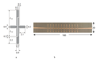
Figure 2Dimensions (mm) of the CRLH unit cell (a) and the fabricated LWA based on a cascade of unit cells (b) (Eberspächer and Eibert, 2010).
Several methods have been proposed in the literature for separating the radiation mode from the total backscattered field, including the minimum/maximum backscatter method, transmission line delay (TLD) method, gain method, series method, and impedance loading (IL) method (Oladapo et al., 2024). Among these, the IL method has been reported to provide high accuracy in certain scenarios (Appel-Hansen, 1979), while the TLD method, originally introduced by Lindsey (1989), relies on time delay principles and is widely used in various applications. Details of these methods are provided in later sections.
In this work, we address the limitation of standard LWAs by utilising LWAs created from right-handed (RH) and left-handed (LH) metamaterials, which enables continuous frequency scanning across forward, broadside, and backward directions. The physical structure of the CRLH LWA, including its unit cell, is shown in Fig. 2, which illustrates the antenna's geometry and design. We adopt and study the TLD and IL method for this CRLH LWA. Specifically, we employ time gating to remove clutter, and our study shows that both methods can isolate the radiation mode field, demonstrating the effectiveness of these methods in analysing the CRLH LWA for enhanced scanning capabilities.
A CRLH LWA enables continuous bidirectional beam scanning by integrating RH and LH elements within its unit cells. This can create a balanced dispersion curve, allowing a smooth transition from negative to positive phase velocity. As frequency increases, the radiation pattern shifts from backward scanning (negative angles) to broadside and then to forward scanning (positive angles), overcoming the unidirectional limitation of conventional LWAs (Caloz and Itoh, 2005).
Frequency bands where radiation occurs can be predicted by the phase constant β(ω) of the propagation mode and the free-space wave number k0. For fast waves, where the phase velocity exceeds the speed of light (), the propagation constant of the leaky mode is real, indicating that the structure radiates power. The frequency scanning characteristics of CRLH LWA are depicted in Fig. 1a with scanning angle θ0 at different frequencies in the forward, backward, and broadside directions. As shown in Fig. 1, the scan angle θ0 is the angle between the main beam radiation and the normal to the propagation axis given as
and beamwidth Δθ
where λ0 is the free-space wavelength and L is the aperture length of the antenna.

Figure 3Backscattered field components of an antenna (a) structure mode scattering (b) structure and radiation mode scattering.
The antenna aperture governs the beamwidth and directivity (Balanis, 2016), and in LWAs, these properties can be adjusted by modifying the leakage rate and the number of unit cells. The CRLH LWA analysed in this work is based on the design methodology presented by Eberspächer and Eibert (2010), which includes capacitive and inductive stubs forming the shunt capacitance and inductance. Specifically, the stub lengths are Lcap=3.85 mm and Lind=6.35 mm. Figure 2 illustrates the physical structure of the antenna, including its unit cell.
The backscattered field is composed of both a structural mode and a radiation mode of scattered fields, corresponding to load-independent and load-dependent scattered fields, as shown in Fig. 3 (Green, 1963).
According to Fig. 3a, the scattering from an antenna is classified as structural mode scattering when its feed port is connected to a matched load. In this configuration, no load impedance contributes to the backscattered signal. However, if a mismatched load is applied at the antenna terminal, part of the received energy is reradiated. As a result, the backscattered field contains contributions from both structural mode and radiation mode fields (Jiang et al., 2009).
Determining the radiation mode field is challenging because only the total backscattered field is measurable. From this, the component associated with the CRLH LWA's radiation mode must be extracted. To accomplish this, the IL and TLD methods are employed. These methods were chosen because the TLD method requires only a single VNA measurement, reducing measurement effort, while the IL method has demonstrated higher accuracy compared to other available techniques.

Figure 4AUT with the impinging field Ei and the total scattered field Et and its equivalent circuit model.
3.1 IL method
To analyse the backscattered field components individually, Ho et al. (2009) suggested a model which employs two impedances terminated at the antenna terminal. By examining the scattering fields in these two scenarios, one can determine the scattering components of an antenna separately for any arbitrary load. According to Ho et al. (2009), the total backscattered field, Et(ZL) of the AUT, when an incident wave is impinging on it, is given as
where is the scattered field of the conjugate matched AUT, Ia is the current flowing into the load ZL when the AUT is matched to , Er is the radiation mode field of the AUT when excited by a unit current and
is the load reflection coefficient. Figure 4 shows the equivalent circuit of a receiving antenna with impedance Za.
Thus, when the load (ZL) matches the conjugate of the antenna impedance (, the antenna reflects only the structure mode. In this scenario, all incident power is assumed to be absorbed by the load, leaving only the structure mode reflected by the antenna. Structure mode reflection depends on the AUT shape, material properties and any fixture attached to AUT and is not influenced by the load reflection coefficient (ΓLoad) like the radiation mode that varies in proportion to it. To ensure that the radiation mode contributes to the backscattered field, the load impedance must not be equal to the conjugate of the antenna impedance. Therefore, a mismatched load should be used as ZL, so that both radiation mode and structure mode are contained in the backscattered field. In real application environments, clutter field Ec is included in the backscattered field Et(ZL) and Eq. (3) becomes
where Etm(ZL) is the modified total backscattered field. The clutter includes the field reflection from the surrounding environment and the coupling between the interrogating antennas of bistatic measurement. This clutter field is independent of the load impedance ZL, and it is removed by either coherent background subtraction or time gating technique. The time gating technique is used in this work. After the clutter filtering, the next is to filter out the structure mode. With the IL method, the structure mode field and the radiation mode field can be separated. The IL method is based on connecting short and open loads at the terminal of the AUT, leading with Eq. (3) to
where , , Γopen=1 and . From Eqs. (6) and (7), radiation mode Ea=IaEr and structure mode Es are given by
Equations (8) and (9) are considered radiation mode and structure mode fields for ideal load impedance termination. For non-ideal cases, the Γopen and Γshort contain parasitic effects due to the load itself or the coaxial port connecting the load to the antenna port. This parasitic effect added capacitance in the case of open load and inductance in the case of short load. These two reflection coefficients can be measured and considered in radiation mode and structure mode fields computation in Eqs. (10) and (11) respectively. Equations (8) and (9) for the ideal radiation mode and structure mode fields can be rewritten for non-ideal cases as
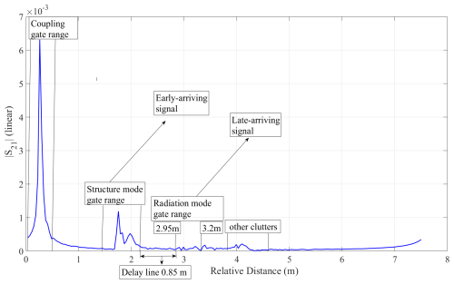
Figure 6Range-domain plot of the backscattered signal (absolute S21 linear) derived from time-domain data.
The relationship between the Es, Er and the incident field Ei can be established through RCS, which is generally given by Lazaro et al. (2013)
where E is the either Es or Er and R is the distance between the scatterer and the radar. The unknown incident field Ei is determined by performing an additional backscatter measurement of an object with a known RCS, which is in this case a sphere with a radius of 0.1 m. If σsphere represents this known RCS, with E given as either Eqs. (8) or (9), for the ideal case and Eqs. (10) or (11) for the non-ideal case then the RCS can be computed using
3.2 TLD method
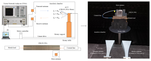
The TLD method is an alternative method which allows the extraction of the radiation modes (Huang, 2016). It is a simple method of tag interrogation as shown in Fig. 5, where a CRLH is connected to a transmission line to produce a delay between radiation mode and structure mode field response. This delay isolates specific structure mode components of the signal based on their arrival time provided the delay between the backscattered fields is sufficiently large. In Fig. 5, the horn antenna and delay line structure effect need to be isolated to extract the radiation mode field of CRLH LWA.
This is done by the time-gating technique (Lambert et al., 1990). The time gating is used to remove the clutter as well as isolate the structure mode component by setting the gate after the delay line, where the late arriving signal (radiation mode field) is extracted. The horn antenna here serves as a receiving antenna that broadcasts the transmitted incident wave from the interrogation antenna to the CRLH LWA which is the AUT under consideration. The CRLH LWA also receives the transmitted incident wave from the interrogating antenna and reradiates back to the horn through a delay line. The interference of these radiations from the horn antenna and the CRLH LWA propagating can interfere and cause side lobes. To minimize this effect, the horn antenna and CRLH LWA can be configured to operate with orthogonal polarizations. This would reduce coupling between the horn antenna and the CRLH LWA, thereby reducing the side lobes.
Figure 6 shows the amplitude of the backscattered signal against relative distance in the range domain. The relative distance (R), is derived from time-domain information using Fourier transformation principles. The relationship between time delay and relative distance follows where c is the speed of light and Δf is the frequency step size. As shown in Fig. 6, the delay line response starts immediately after the early-arriving signal (structure mode) and ends before the first late-arriving signal (radiation mode). By setting the gate range at the end of the delay line (2.8 m) and the end of the late-arriving signal (3.2 m), the radiation (antenna) mode response of the CRLH LWA is extracted while gating out the structure mode, the coupling, and other clutter effects in the backscattered signal. The radiation mode RCS for the TLD method can be computed using Eq. (13).
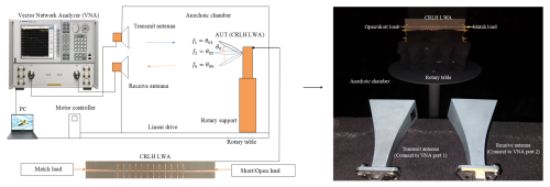
The bistatic measurement technique is used and the set-up consists of a VNA and two X-Band WR-90 standard gain horn antennas as transmit and receive antennas. Each X-Band horn antenna is connected to port 1 and port 2 of the VNA respectively. The anechoic chamber contains a rotary support and a linear drive. The CRLH LWA is the AUT for the case of the IL method and the CRLH LWA is connected to the horn antenna through a transmission (coaxial) line for the case of the TLD method. The AUT is placed in both cases on the rotary table in the anechoic chamber and aligned to face the X-Band horn antennas on the measurement table. The AUT and the horn antennas are separated by 1.5 m automatically by the linear drive. The distance of 1.5 m corresponds to the far field distance based on the largest dimension of the CRLH LWA. The setups for both methods are shown in Figs. 7 and 8. The VNA continuously collects frequency sweeps of S21 data from 8 to 12 GHz in 201 points for different azimuth angles from −500 to 500.
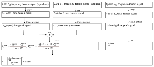
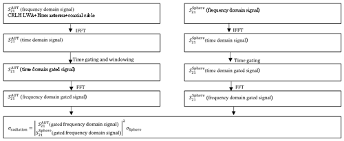
The collected data are again processed in the time/range domain to extract reflection by applying the Tukey window (Harris, 1978) and time gating. In this post-processing, inverse fast Fourier transform (IFFT) is applied to convert the collected S21 parameter of the total backscattered signal to the time domain. For the case of the IL method, the IL model is applied according to Eq. (8), and then time gates were applied to remove the coupling effect between the transmitting and receiving horn antennas and clutter that may occur. For the TLD method time gate applying Tukey window is used to isolate the coupling effect between the two horn antennas and the structure mode effect of the CRLH LWA and the connected horn antenna. After the time gating process in the IL method and windowing in the TLD method, inverse fast Fourier transform (FFT) is applied to convert the time domain radiation mode S21 to the frequency domain radiation mode S21. Radiation mode RCS is computed using Eq. (11) with a sphere of 0.1 m of radius chosen as a reference target. The post-data processing procedure for both IL and TLD methods are summarised as shown in Figs. 9 and 10 respectively.
The difference between the IL and TLD methods is that IL involves twice the number of VNA measurements of CRLH LWA with two terminated impedances, one after the other, unlike the TLD method, which involves a one-time VNA measurement. Also, both the radiation mode and structure mode field can be determined using IL as shown in Fig. 9 while the TLD can only determine the radiation mode. The acquired measurement data used for analysis is available in (Oladapo, 2025b).
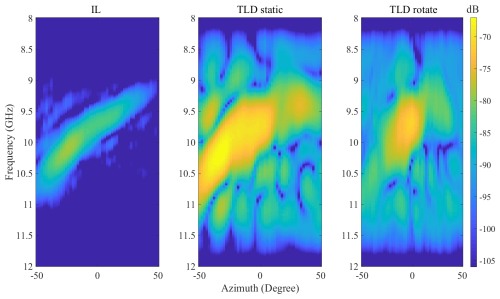
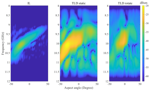
Figures 11 and 12 show the peak values of the radiation mode S21 and RCS within the operating frequency band of the CRLH LWA. The analysis reveals the frequency-dependent features of the CRLH LWA across azimuth angles. The IL method shows S21 and RCS amplitude peaks over a frequency range from 9.14 to 10.66 GHz, with an angular range from −50 to 50°. The TLD method, which uses a static horn antenna and a rotating CRLH LWA, achieves S21 and RCS amplitude peaks over a frequency range from 9.22 to 10.84 GHz, with a reduced angular range from −50 to 36°. The reduced angular coverage is due to side lobes which are more significant in the TLD method than the IL method. These side lobes cause some amplitude peaks to appear at the same frequency but at different azimuth angles. The side lobes arise because the CRLH LWA receives the incident wave simultaneously with the horn antenna from the interrogating antenna. This wave reradiates back to the horn antenna through the coaxial cable and interferes with the radiation mode of the CRLH LWA. To minimize this effect, the horn antenna and CRLH LWA should operate with orthogonal polarization. This will be investigated in the future. When both the CRLH LWA and the horn antenna rotate in the TLD method, S21 and RCS amplitude peaks span from 9.28 to 10.92 GHz, with the least angular range from −50 to 18°. This setup of TLD shows less frequency dependency of the CRLH LWA across the azimuth angles and indicates the reason for limited angle coverage across the azimuths.
It is also worth noting that the TLD method with a static horn antenna results in higher amplitude values, as shown in Figs. 11 and 12. This is because the horn antenna remains fixed and oriented perpendicular (normal) to the direction of the incoming wave, allowing it to maintain high gain and efficiently receive energy across all azimuth angles. In contrast, when the horn antenna is rotated, its orientation deviates from the incident wave direction, reducing its effective gain and resulting in a lower received amplitude.
The RCS computed using Eq. (11) follows the same pattern as the radiation mode S21 in Fig. 11 except that the amplitude changes as shown in Fig. 12. The reason for this is attributed to the gain contribution from the horn antenna as explained earlier.
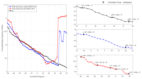
Figure 13 shows the frequency at which the maximum radiation modes S21 and RCS occur, providing a frequency to relative azimuth angle mapping of the CRLH LWA. As shown, the peaks of the RCS and S21 of the radiation mode occur at the same frequencies at some azimuth angles, causing frequency ambiguity. Table 1, extracted from Fig. 13, indicates that the worst frequency ambiguity along the azimuth is 4°. These ambiguities are present in both the IL and TLD methods, as shown in Table 1, and may be attributed to side lobes that appear at the same frequency but at different angles. In the TLD method, side lobes could result from interference between the horn antenna and the CRLH LWA, while in the IL method, side lobes may arise due to the inherent parasitic effects of the coaxial ports and the impedance termination at the CRLH LWA terminal.
An analysis has been carried out on estimating the relative incident angle to the CRLH LWA using the frequency response of the radiation mode S21 and RCS, extracted through the IL and TLD methods for separating backscattered field components. The IL method provides broader angular coverage within the operational frequency band of the CRLH LWA but requires two measurements per reactive load condition at the antenna terminal. In contrast, the TLD method, particularly when using a static horn, offers a more streamlined, one-time measurement process, albeit with reduced angular and frequency coverage. Both IL and TLD (with static horn) methods demonstrate potential in estimating the relative angle due to the dispersive and frequency-dependent characteristics of the CRLH LWA across a wide azimuth range. The choice between these methods depends on application-specific trade-offs between angular coverage and measurement simplicity.
Although the TLD method successfully isolates the radiation mode using a coaxial delay line and time-domain gating, some residual interference from the illuminating horn antenna was observed. As mentioned earlier in the previous section, one potential mitigation approach is to employ orthogonal polarisation between the CRLH LWA (AUT) and the horn antenna. In addition, future work may explore introducing slight frequency offsets between the CRLH LWA (AUT) and the horn antenna. This frequency shift could facilitate spectral separation of the radiation and structure modes, enhancing isolation via joint time-frequency analysis. Moreover, advanced signal processing techniques inspired by Inverse Synthetic Aperture Radar (ISAR) imaging and Frequency Selective Surface (FSS) measurement methods may offer additional opportunities for improving angular resolution and robust radiation mode extraction.
The MATLAB scripts used for processing and analyzing the measured data are openly available in Figshare (Oladapo, 2025a).
The data were captured in the anechoic chamber of the Faculty of Electrical Engineering, THWS, using a vector network analyzer (VNA). The complete dataset is openly available in Figshare (Oladapo, 2025b).
MAE and JAO developed the concept of this work. JAO implemented the signal processing, carried out the measurements and drafted the manuscript. SBA and MAE supported the work, reviewed and edited the paper.
At least one of the (co-)authors is a member of the editorial board of Advances in Radio Science. The peer-review process was guided by an independent editor, and the authors also have no other competing interests to declare.
Publisher’s note: Copernicus Publications remains neutral with regard to jurisdictional claims made in the text, published maps, institutional affiliations, or any other geographical representation in this paper. While Copernicus Publications makes every effort to include appropriate place names, the final responsibility lies with the authors.
This article is part of the special issue “Kleinheubacher Berichte 2024”. It is a result of the Kleinheubacher Tagung 2024, Miltenberg, Germany, 24–26 September 2024.
The authors would like to acknowledge the innovation Faculty of Electrical Engineering, Technical University of Applied Sciences Würzburg-Schweinfurt (THWS), for general support and provision of research facilities.
This research was supported by the Deutscher Akademischer Austauschdienst (DAAD) – Nigerian–German Postgraduate Training Programme grant ID (57610608).
This paper was edited by Ludger Klinkenbusch and reviewed by Tobias Rommel, Uwe Siart, and one anonymous referee.
Appel-Hansen, J.: Accurate determination of gain and radiation patterns by radar cross-section measurements, IEEE T. Antenn. Propag., 27, 566–570, https://doi.org/10.1109/TAP.1979.1142156, 1979.
Balanis, C. A.: Antenna Theory: Analysis and Design, 4th Edition, John Wiley & Sons, Hoboken, NJ, USA, ISBN 9781118642061, 2016.
Caloz, C. and Itoh, T.: Electromagnetic Metamaterials: Transmission Line Theory and Microwave Applications: The Engineering Approach, Wiley, https://doi.org/10.1002/0471754323, 2005.
Eberspächer, M. A. and Eibert, T. F.: Leaky wave antenna with amplitude controlled beam steering based on composite right/left-handed transmission lines, Adv. Radio Sci., 8, 27–32, https://doi.org/10.5194/ars-8-27-2010, 2010.
Green R. B.: The general theory of antenna scattering, Rep. 1223-17, Electro-Science Lab., Ohio State Univ., Columbus, OH, p. 11. Contract AF 33(616)-8039; AD 429 186, 1963.
Harris, F. J.: On the use of windows for harmonic analysis with the discrete Fourier transform, Proc. IEEE, 66, 51–83, https://doi.org/10.1109/PROC.1978.10837, 1978.
Ho, T. Y., Chen, S. Y., and Li, H. J.: A method to determine the structure mode and antenna mode of a RFID tag antenna scattering, IEEE Antennas Prop., 1–4, https://doi.org/10.1109/APS.2009.5171642, 2009.
Huang, H.: Antenna sensors in passive wireless sensing systems, in: Handbook of Antenna Technologies, 4, https://doi.org/10.1007/978-981-4560-44-3_86, 2016.
Jiang, W., Liu, Y., Gong, S., and Hong, T.: Application of bionics in antenna radar cross section reduction, IEEE Antennas Wirel. Pr., 8, 127–130, https://doi.org/10.1109/LAWP.2009.2037168, 2009.
Johnson, R. C. and Jasik, H.: Antenna Engineering Handbook, 3rd Edition, McGraw-Hill, New York, NY, USA, ISBN 978-0070323810, 1993.
Karmokar, D. K. and Guo, Y. J.: Planar leaky-wave antennas for low-cost radar, Proc. IEEE-APS Topical Conf. Antennas Propag. Wirel. Commun., 112–115, https://doi.org/10.1109/APWC.2017.8062255, 2017.
Lambert, K. M., Rudduck, R. C., and Lee, T. H.: A new method for obtaining antenna gain from backscatter measurements, IEEE T. Antenn. Propag., 38, 739–743, https://doi.org/10.1109/8.55588, 1990.
Lazaro, A., Ramos, A., Girbau, D., and Villarino, R.: A novel UWB RFID tag using active frequency selective surface, IEEE T. Antenn. Propag., 61, 1155–1165, https://doi.org/10.1109/TAP.2012.2228838, 2013.
Lindsey, J. F.: Radar cross-section effects relating to a horn antenna, IEEE T. Antenn. Propag., 37, 214–218, https://doi.org/10.1109/8.18716, 1989.
Oladapo, J. A.: MATLAB code for Backscattering-Based Radiation Mode Analysis for Angle Estimation of a CRLH Leaky Wave Antenna, Figshare [code], https://doi.org/10.6084/m9.figshare.29973286, 2025a.
Oladapo, J. A.: Measurement dataset for Backscattering-Based Radiation Mode Analysis for Angle Estimation of a CRLH Leaky Wave Antenna, Figshare [data set], https://doi.org/10.6084/m9.figshare.29973316, 2025b.
Oladapo, J. A., Adrian, S. B., and Eberspächer, M. A.: Frequency-dependent RCS characterization of a CRLH-based leaky wave antenna, in: Proc. Kleinheubach Conf. 2024, Miltenberg, Germany, 23–25 September 2024, 1–4, https://doi.org/10.23919/IEEECONF64570.2024.10739083, 2024.
Saeed, N. H., Farhan, M. J., and Al-Sherbaz, A.: Design and analysis of microstrip antenna for 5G applications, J. Eng. Sustain. Dev., 28, 163–174, https://doi.org/10.31272/jeasd.28.2.10, 2024.
Suliman Munawar, H.: Applications of leaky-wave antennas: a review, Int. J. Wirel. Microwave Technol., 10, 56–62, https://doi.org/10.5815/ijwmt.2020.03.05, 2020.
Xu, F., Wu, K., and Zhang, X.: Periodic leaky-wave antenna for millimeter wave applications based on substrate integrated waveguide, IEEE T. Antenn. Propag., 58, 340–347, https://doi.org/10.1109/TAP.2009.2026593, 2010.
Yang, S. T. and Ling, H.: RCS of a microstrip leaky-wave antenna, IEEE Antennas Wirel. Pr., 12, 35–38, https://doi.org/10.1109/LAWP.2012.2236677, 2013.


