 | 01 Sep 2025
Application of two movable antennas in a compact radar test range for angular measurements
Markus Tafertshofer
Oliver Arnold
Kilian Hampp
Erwin Biebl
This work presents the application of two movable antennas in a compact radar test range for testing the angular resolution of radar systems in an automotive environment. The goal is to simulate two targets in the azimuth direction, which are measured by a radar placed in the quiet zone. At first, a mathematical approach to the problem is presented. Afterwards, a ray tracer in MATLAB is used for the setup simulation, and measurements are carried out to validate the calculation and simulation results. The effects occurring in the simulation and measurements are analyzed, and strategies to mitigate them are presented. Overall, the results look promising, and the system is suitable for testing the angular resolution of radar systems.
- Article
(7017 KB) - Full-text XML
- BibTeX
- EndNote


Current research has a strong focus on the development of automotive driving (AD). Various systems, e.g., lidar, radar, ultrasonic, or optical systems, are used to obtain information on the current driving situation (Trovao, 2019). Each of these systems has to pass extensive testing before it can be implemented into an AD system. The application of radar is one of the prerequisites to autonomous driving (Bilik et al., 2019), as these sensors allow the estimation of position, velocity, and type of traffic members and obstacles. Nowadays, radar target simulators (RTSs) are used to test radar systems. Various RTSs have been reported. Engelhardt et al. (2016) describe a simple system that receives the radar signal and allows an analog manipulation before the signal gets transmitted back to the radar. Asghar et al. (2021) describe a system with movable antenna towers to include spatial testing of radar systems. Another system is reported in Diewald et al. (2022), where an antenna array is used to digitally alter the spatial target position by superimposing the signals sent from the RTS. An even larger array is proposed by Dallmann et al. (2018). Further systems are developed by Rohde & Schwarz (2021), Keysight Technologies (2017), or dSpace GmbH (2020), for example. However, with large aperture sizes for high-angular-resolution measurements, these systems have limitations when it comes to long-range radar testing. Large free-space ranges are necessary to achieve plane wave conditions over the aperture. Compact test ranges are an option to resolve this issue. To enable angular-resolution measurement in a compact test range, two RTS antennas can be applied in an offset to the reflector's focal point. Challenges and issues arising from this setup are addressed in this paper.
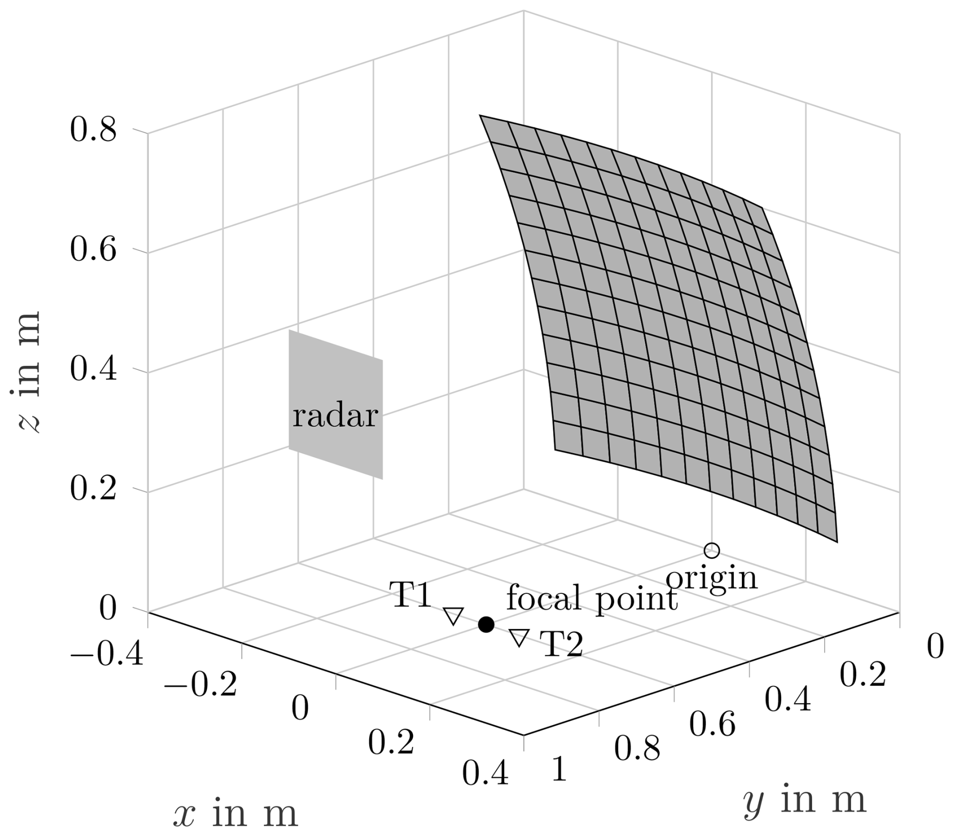
The following section gives an insight into the utilized system. The parameters of the compact test range reflector and the setup of the antennas and radars are described briefly. A schematic reflector setup is depicted in Fig. 1. The setup is designed for a frequency of 77 GHz.
2.1 Compact range
Compact test ranges are used for collimating incoming plane waves to a focus point and vice versa to generate nearly plane waveforms in a short distance (Balanis, 2016). Therefore, these devices can be used to simulate far-field conditions at a relatively near distance. A device under test is placed in the quiet zone (QZ), where the phase and amplitude of the field are nearly constant, whereas the measurement device is placed in the focal point. For the angular testing of radar systems, multiple targets are necessary. As the radar is placed in the QZ for the quasi-plane wave, the targets have to be placed at the focal point. However, this is not directly possible, leading to an offset of the target antennas T1 and T2 as shown in Fig. 1. Therefore, disturbing effects will occur. For example, as the plane wave criterion is only fulfilled when the target is in the focal point, phase and amplitude deviations of the field will increase with an increasing distance of T1 and T2 from the focal point. Furthermore, the signal still reaching the targets will become weaker as the reflector collimates the incoming waves from the QZ to the focal point. However, in the calculations, these effects are neglected in order to get a simple estimation. The utilized test setup is based on a paraboloid reflector with the equation
with x, y, and z corresponding to Fig. 1 and F=0.6 m being the focal length. It is an offset reflector with blended rolled edges (Gupta et al., 1990) and an overall size of 0.6 m by 0.6 m. After calibration, the reflector yields an amplitude deviation of ±0.36 dB and a phase deviation of ±2.89° over a circular QZ with a 20 cm diameter, tested by a 60 mm radius sphere. These parameters fulfill the requirements from Parini et al. (2020) of ±5° phase and ±0.5 dB amplitude deviation over the QZ.
2.2 Target antennas
Two short-circuited standard 10 dBi rectangular horn antennas are used as targets. Both antennas are mounted on a movable cart controlled by a computer. The maximum distance between the antennas is 30 cm. The antennas are pointed towards the reflector and have an elevation angle of 46.3° and are positioned on a straight line through the focal point as depicted in Fig. 1.
2.3 Radar positioning
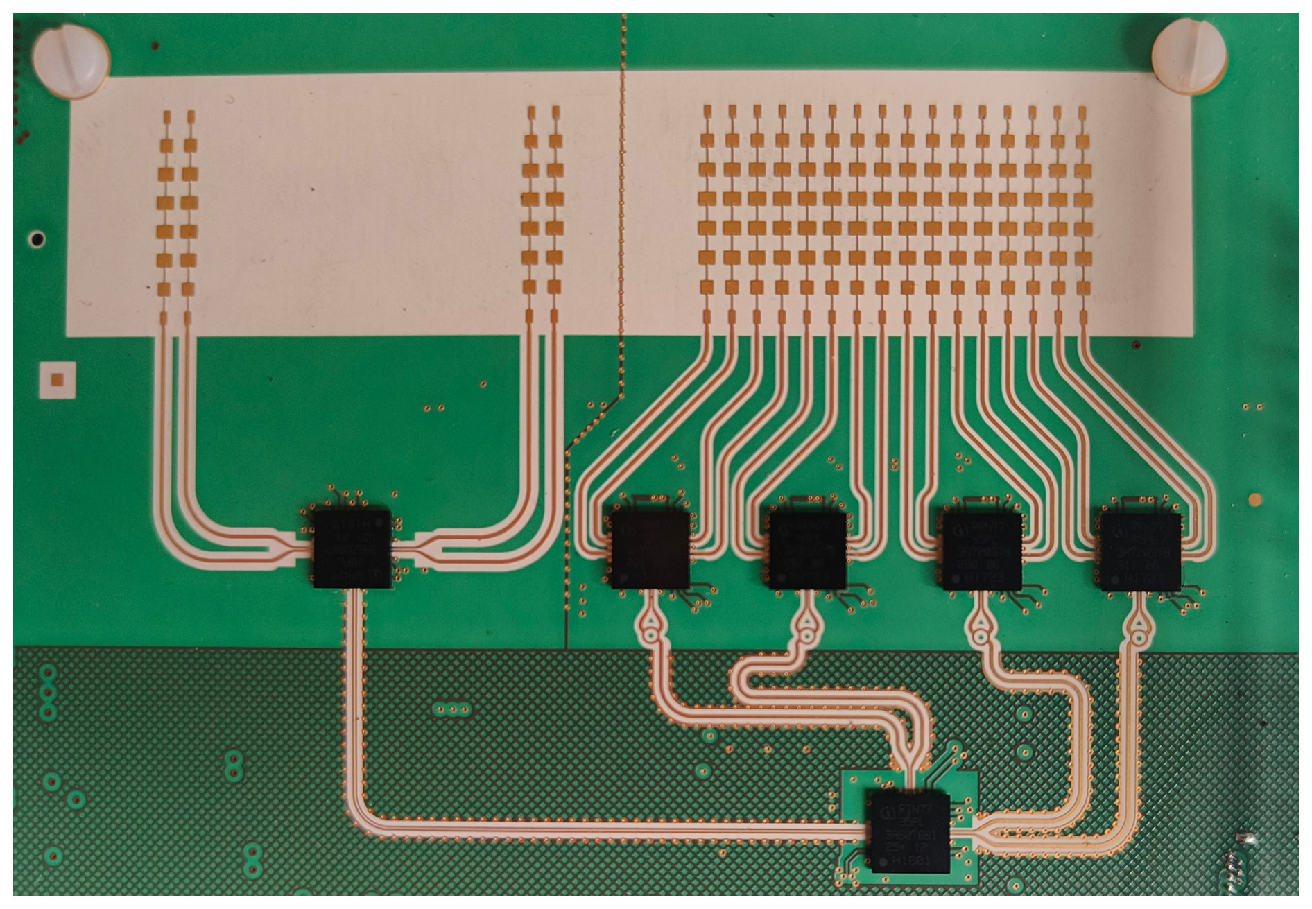
The radar used in the test cases is a Radarbook2 from INRAS and is depicted in Fig. 2. It is an FMCW radar system at 77 GHz and consists of 2 TX and 16 RX antennas arranged in a linear array, resulting in 32 virtual antennas. To evaluate the target parameters, a fast Fourier transform (FFT) over the chirps and the antenna array is performed. A simple estimation for the angular resolution of such a radar system can be found in Bilik et al. (2019) and is in radians, leading to Δθ=3.7°. The radar is positioned in three different setups in the QZ. Firstly, the TX antennas are centered in the QZ, secondly, the RX antennas are centered in the QZ, and thirdly, the radar itself can be centered in the QZ. Other positions are also possible, of course.
The following section provides an analysis of the system and the expected angle in dependence of the target positions. The 2-dimensional setup, depicted in Fig. 3, is used for the calculation. Thereby, the reflector can be modeled by (Tafertshofer et al., 2024)
with and the focal distance F=0.6, as mentioned before. For simplification, the vertical TX vector is used to calculate the incoming angle at the QZ. The gradient of the reflector is calculated by taking the derivative of Eq. (2), which leads to
Applying the simplification that the TX ray used for calculation is vertical, the incidence angle θi at the reflector can be computed with
With the law of reflection and the x position x=Δx of the corresponding antennas T1 and T2, the incoming angle θ can be calculated to
The x position of the antennas for a certain angle is then determined by
It has to be noted that the physical position of the targets is not equal to the virtual position measured. The virtual position can be estimated by
with r being the distance from the radar to the reflector plus the focal distance.
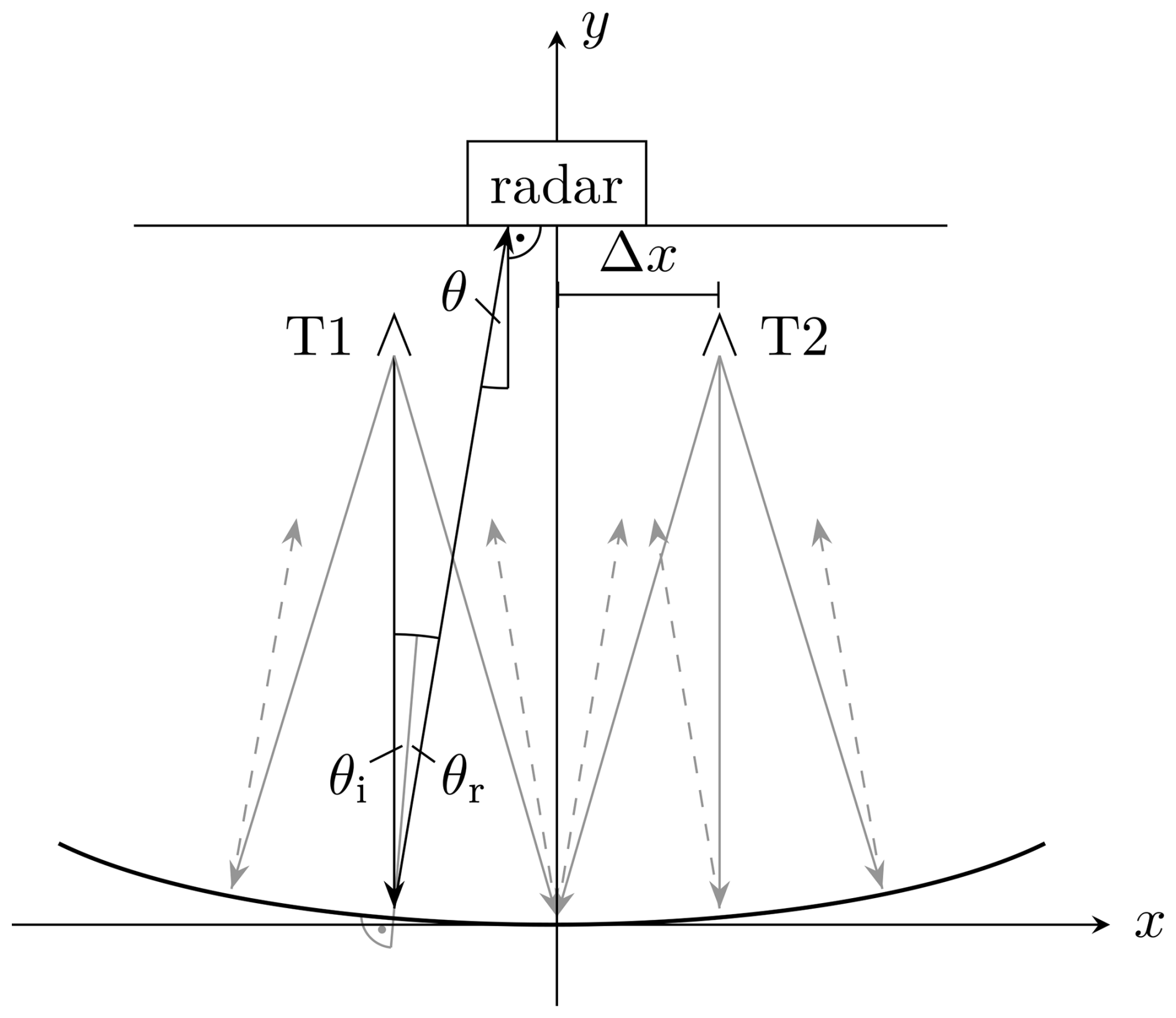
Figure 3Top-down view of the setup with the antennas T1 and T2 and the radar setup centered relative in the QZ (Tafertshofer et al., 2024).
This section presents the results obtained by the simulation and measurement. Furthermore, the results are compared, and the occurring effects are mentioned.
4.1 Simulation
A ray-tracing simulation is performed to verify the calculation as shown in Tafertshofer et al. (2024). The radar system is replicated in the simulation to generate results comparable to those of the measurement. Windowing of the received signals was neglected at the cost of sidelobes in the FFT, as it would reduce the angular resolution.
As the most intuitive positioning of the radar is centered in the QZ, this setup will be analyzed here. Additionally, some effects occurring at the other mentioned positions will be scrutinized. The simulation is done for various angles between 1 and 7°. Some results are presented in Fig. 4, where the white lines provide the theoretical angle obtained by calculations. As can be seen in Fig. 4a and b, only one target appears for angle differences smaller than the angular resolution of the radar system of 3.7°. Finally, in Fig. 4c and d, the targets can be separated, and the simulation is a good match to the calculation. The simulation results for the RX and TX-centered setups are similar, as already shown by Tafertshofer et al. (2024).
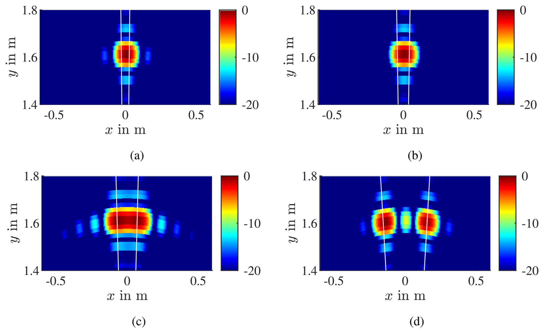
Figure 4Simulation results of targets at (a) ±1°, (b) ±1.5°, (c) ±2.5°, and (d) ±5.5° with radar centered in QZ. The white lines indicate the theoretical angle obtained by calculations.
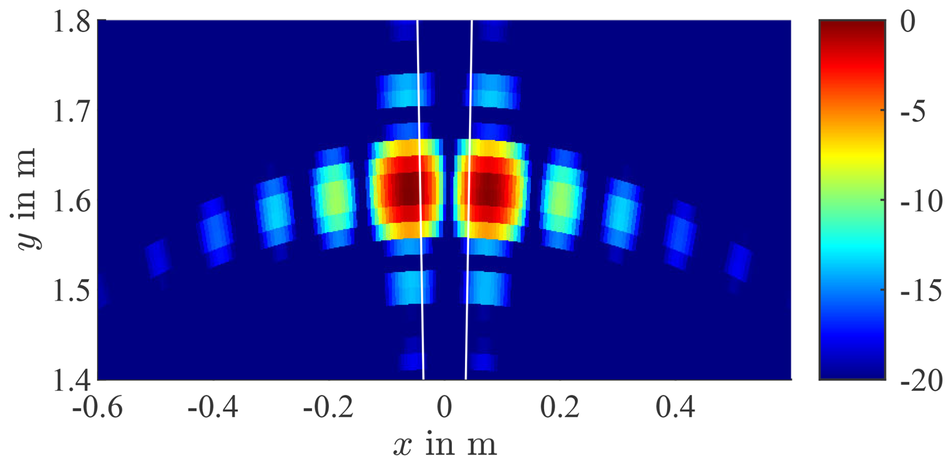
Figure 5Simulation results of targets at ±1.5° with RX antennas centered in QZ. The white lines indicate the theoretical angle obtained by calculations. The targets appear at −2.36 and 2.58°.
It has to be mentioned that for simulated angles smaller but close to the radars' angular resolution, there is a possible setup where two targets are visible. This effect is shown in Fig. 5, where the simulation results for targets at ±1.5° are depicted with the RX antennas centered in the QZ. As the angular resolution of the radar is smaller than the angular distance of the targets, only one target is expected to be visible. Nevertheless, two targets appear at the angles −2.36 and 2.58°. This is an effect of the interference generated by the two targets and is analyzed further in Sect. 5.4.
4.2 Measurement
The measurement setup is depicted in Fig. 6. Additional absorbers are added while measuring to reduce unwanted reflections. Both radar and antennas are movable along linear axes. As the E-band flange of standard waveguide antennas is too large to allow small angles, the antennas are modified and have a 90° waveguide bend before the flange. Comparing the measurements in Fig. 7 to the simulation results in Fig. 4, it is notable that they are very similar. Even the ghost target in Fig. 7d is observable. The target separation is slightly better in Fig. 7c than in the simulation. Similar to the simulation, when the angle is lower than the resolution ability of the radar, two targets instead of one appear for the RX antennas centered case, as depicted in Fig. 8 for targets at ±1°. In this case, the appearing targets have angles of −2.92 and 2.47°.
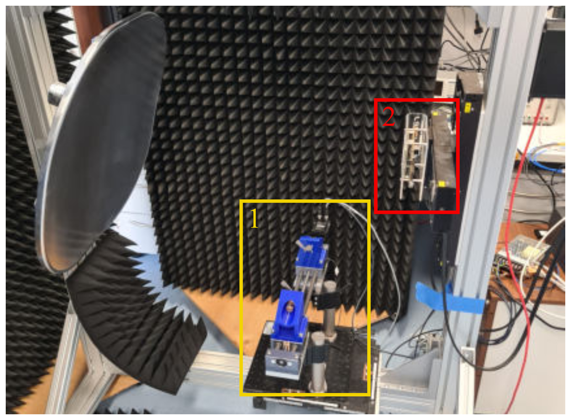
Figure 6Measurement setup. Box (1) depicts the movable antennas, and box (2) is the radar. Additional absorbers are placed around the antennas and the radar for the measurements to reduce unwanted reflections.
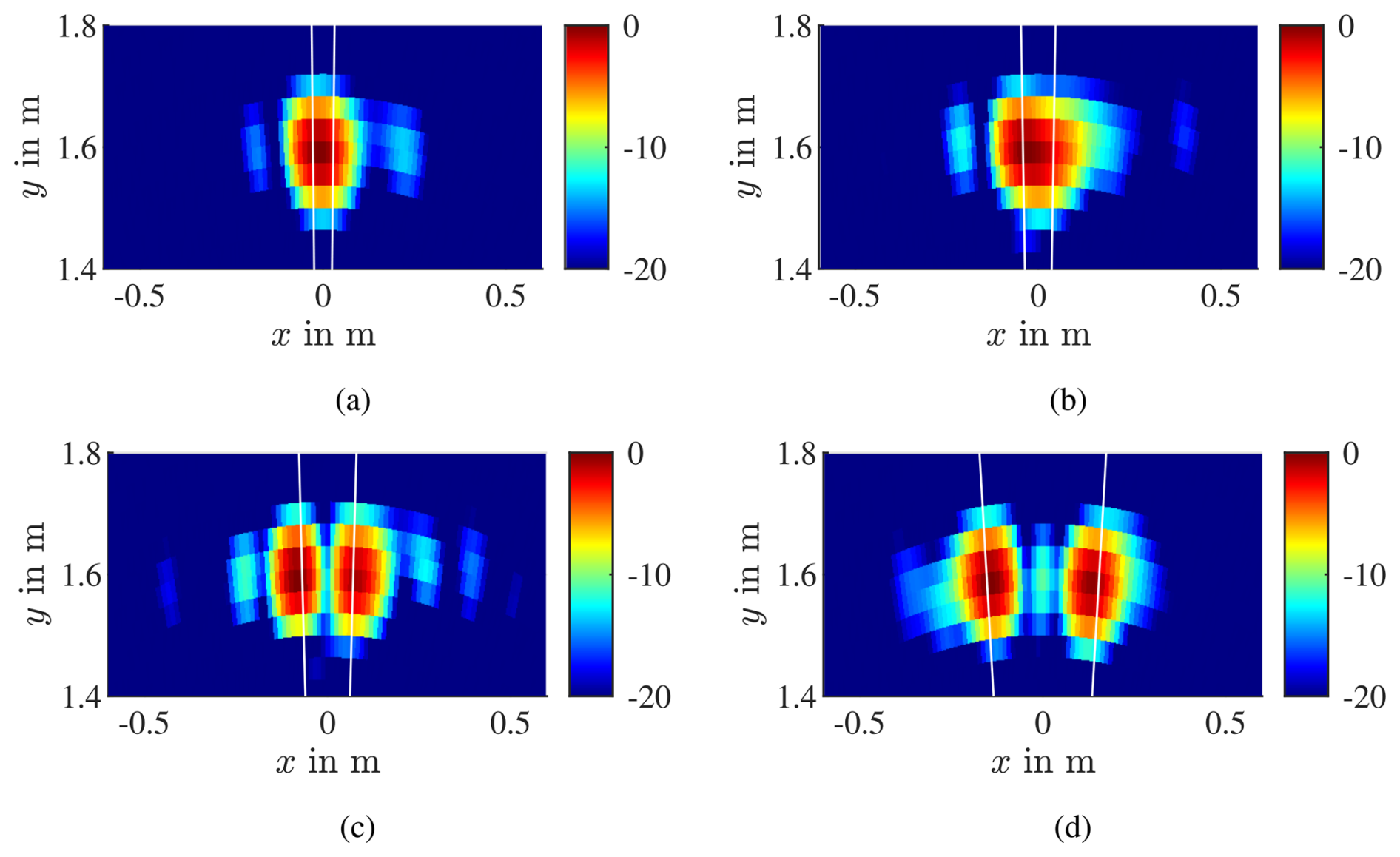
Figure 7Measurement results of targets at (a) ±1°, (b) ±1.5°, (c) ±2.5°, and (d) ±5.5° with radar centered in QZ. The white lines indicate the theoretical angle obtained by calculations.
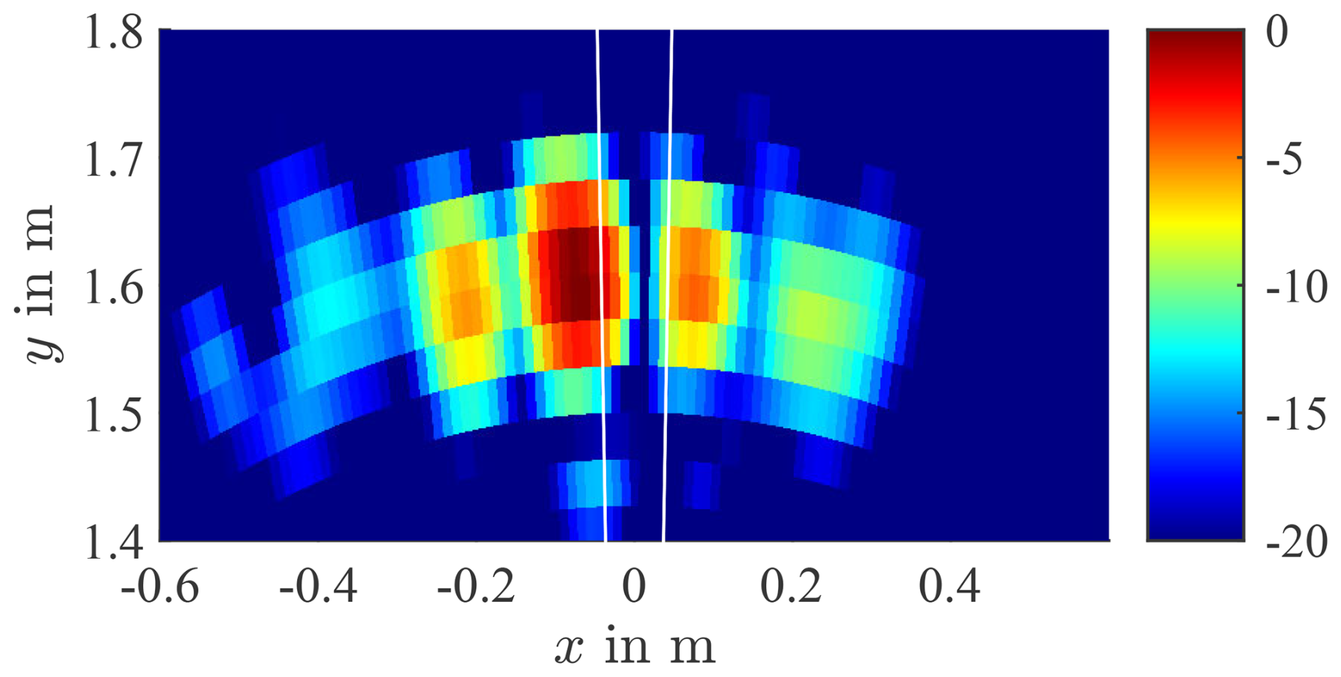
Figure 8Measurement results of targets at ±1° with RX antennas centered in QZ. The white lines indicate the theoretical angle obtained by calculations. The targets appear at −2.92 and 2.47°.
As the results show, the generation of multiple targets in a compact radar test range works well, with some occurring effects. This section provides the reason for these deviations after a short comparison between the calculation, simulation, and measurement results.
5.1 Comparison
Table 1 shows the results for the radar-centered setup. As can be seen, the calculation and simulation match with small deviations very well. The simulation and measurement at 1 and 1.5° should yield results at 0° but show some offset. As the values are equal for both cases, this may be caused by the accuracy of the angular FFT. The measurements where two targets appear also show some deviations and are shifted slightly to lower angles. Applying a window function in the signal processing will compensate for this shifting effect, as depicted in Fig. 9 for an angle of 5.5°. However, only the simulated results get compensated for completely, whereas the measurement is still shifted to lower angles after windowing, which implies that the positioning and alignment of the radar and antennas to the compact test range can be improved. As the windowing decreases the angular resolution of the radar, it was not applied to the measurements and simulations in this work.
Table 1Comparison of the results for the radar-centered setup.
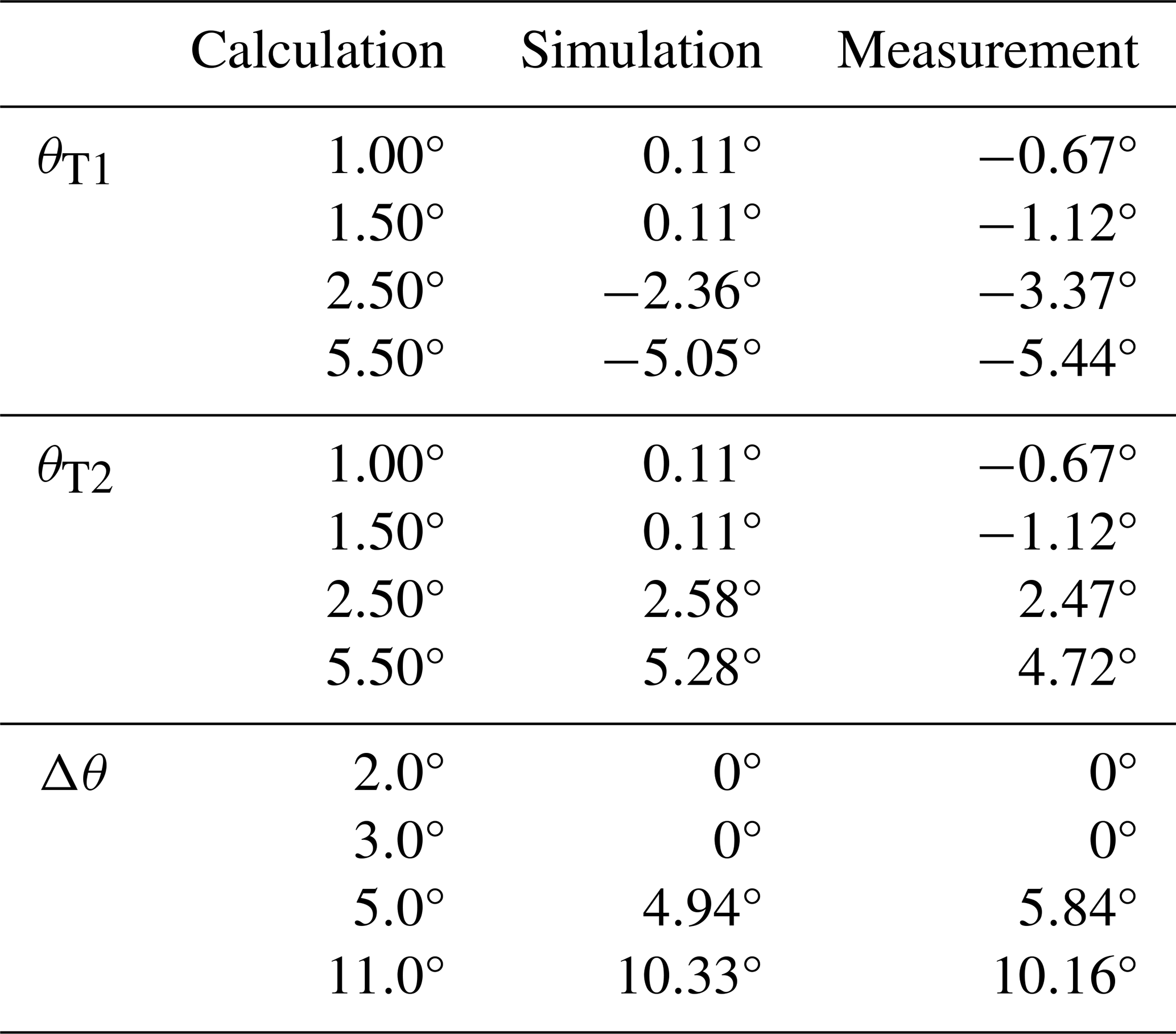
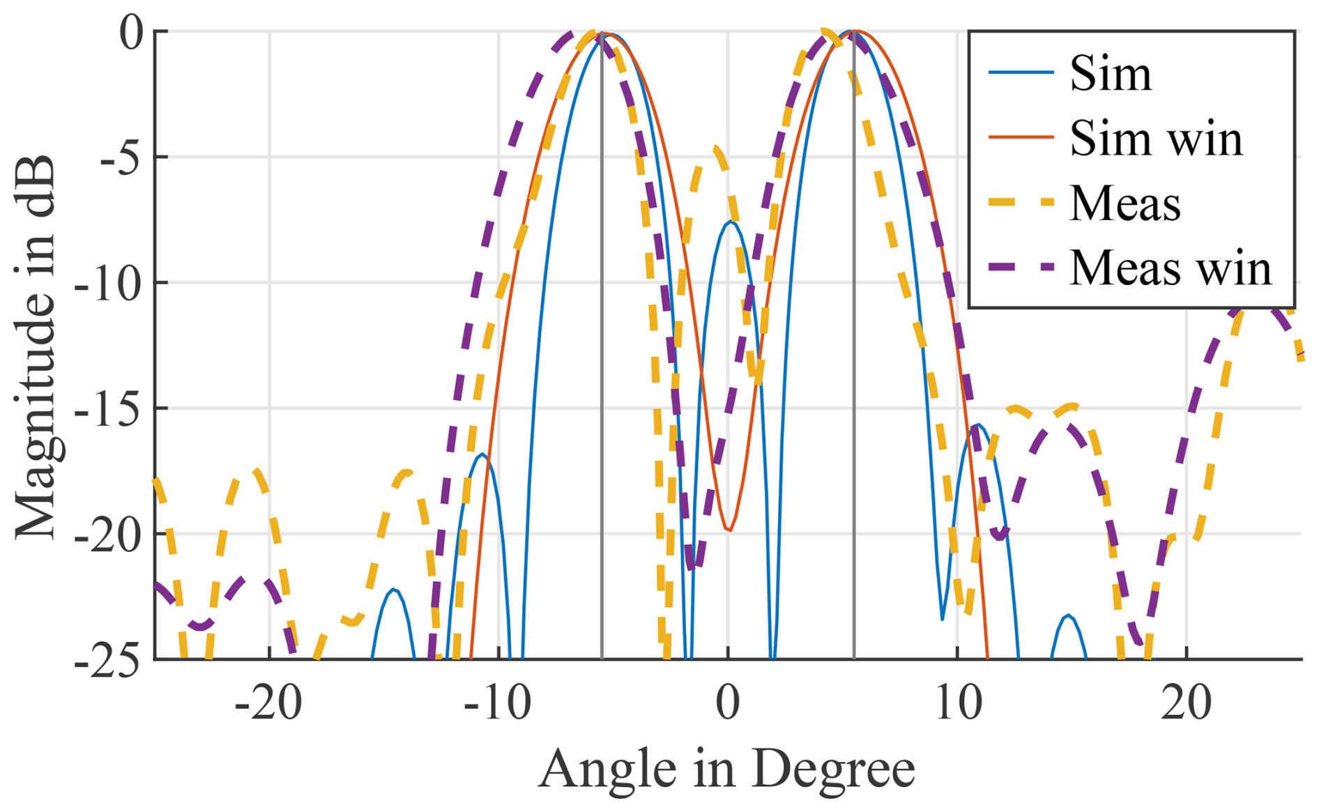
Figure 9Simulation results for a target at 5.5° without and with the application of a Chebyshev window with a sidelobe attenuation of 40 dB. The black lines indicate the calculated angle.
5.2 Ghost target at 0°
The ghost target appearing in the simulations and measurements for large angles is analyzed here. Overall, the ghost targets occur due to the sidelobes of the FFT. Additionally, simulations and measurements show that the magnitude of this target is also influenced by the radar position. Presumably, there are positions where the signal strength at the antennas is influenced in a manner that antennas towards the edges have a lower weighting in the FFT. However, it is not convenient to search for a radar position where these ghost targets do not appear. Therefore, applying a window function to the results is an option to reduce this effect at the cost of lower angular resolution. Fortunately, the ghost targets only appear at angle differences that are at least twice as high as the angular resolution, which enables the application of a windowing function.
5.3 Phase error from compact range setup
Two main problems occur regarding the phase of the transmitted signal. First of all, a phase error will be introduced due to the offset of the targets to the focal point of the mirror compared to an ideal compact test range. Secondly, the physical position of the targets is not the same as their virtual position. Comparing a free-range test setup and a compact test range setup with identical target angles, the phase difference between the signals of all transmit antennas at a target should be equal to achieve identical results. This effect is simulated and depicted in Fig. 10. It is clearly visible that there is a deviation between the case with a reflector and without a reflector. However, compensating for this effect in the simulations has no influence on the results. Furthermore, the MIMO array has one redundant antenna element, which can be used to mitigate the phase errors occurring due to this reflection.
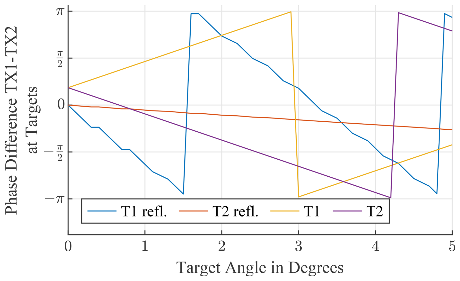
Figure 10Simulation of the phase difference for the TX signals of antenna TX1 and TX2 at the targets T1 and T2, respectively.
5.4 Target splitting at small angles
The target splitting at small angles, as depicted in Figs. 5 and 8, is an effect of the interference pattern generated by the two targets. The pattern over the QZ and the part received by the radar is depicted in Fig. 11. As can be seen, the radar receives an interference pattern with two nearly identical local maximum values, which are not equal to the absolute interference maxima. However, when the maximum values of the measured pattern are used for computing the distance between the sources (Hecht, 2009), the resulting angle is slightly higher than the actual angle, which results in the wrong radar images. Fortunately, this error can easily be mitigated by windowing. Another option is to move the radar slightly along the x axis to introduce a higher difference between the local maximum values.
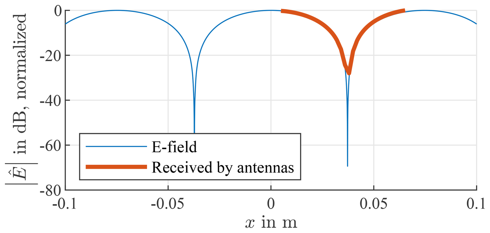
Figure 11Simulation of the interference pattern generated by the targets in the QZ for targets at ±1.5°. The orange part is measured by the radar at an RX-centered position.
5.5 Incoming angle variation
Due to the offset of the targets to the focal point of the reflector, the incoming angle varies over the QZ. The simulation results for the antenna T1 are depicted in Fig. 12. For simplification, only the furthest left and right rays are depicted. For reference, the vertical ray is utilized. As shown in Fig. 12a, the angle variation over the radar aperture is below 0.04° for all measured angles. When the aperture is increased to the size of the QZ or twice the size of the QZ as depicted in Fig. 12b and c, respectively, the maximum angle deviation increases as expected. As the simulation borders are fixed and the antennas move to the borders, the deviation of one of the rays declines with increasing angle until the position is equal to the simulation border. Due to this angle variation, some errors in the absolute angle measurement appear. This error can not be compensated for in this test setup, as it results from the geometrical conditions. However, for angles below 2°, the deviation is below 2.5 %, which does not strongly affect the results.
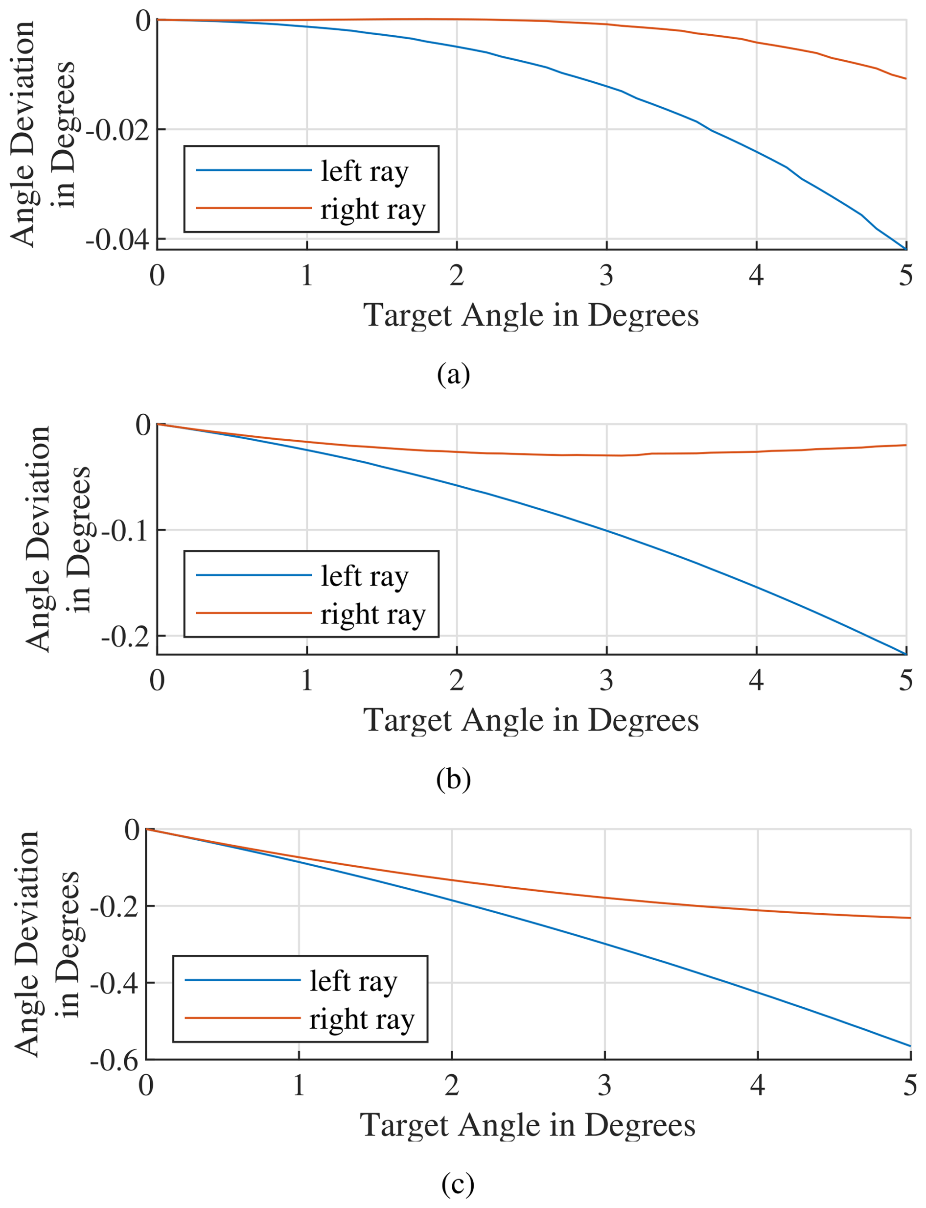
Figure 12Simulation of the angle difference between the calculated angle and the leftmost (negative x) and rightmost (positive x) ray, respectively. Over the radar aperture (a), the QZ (b), and 2 times the QZ (c).
An approach to simulate two targets for angular testing in a compact range is presented. The promising results show that the system is suited for such a scenario, but some accompanying effects must be considered. First of all, depending on the radar signal processing and position, there is the possibility that ghost targets appear between the actual targets. Furthermore, a splitting of targets that are too near to each other to be resolved by the radar may occur. These two effects can be handled by applying a window function on the antenna array. A target shifting to smaller angles is present but can be removed if the measurement range is calibrated with a well-known radar system. The difference between physical and theoretical positions can be used to compensate for the effect if the target antennas can be moved independently. The error introduced by the offset of the target antennas to the focal point is very small for angles below 2° over the QZ but can get significant for higher angles. Therefore, the measurement will have increasing inaccuracies at higher angles. However, it can be said that most of the effects discussed here can be mitigated by simple calibration routines and signal processing.
Some additional work has to be done. As the setup was only tested with a linear antenna array, and the measurements show some effects generated by moving the radar to other positions, the behavior with other MIMO radar systems has to be analyzed to prove that the system generally works. Additionally, instead of targets simulated by short-circuited antennas, real radar target simulators can be used in this test environment to enable testing of the distance, velocity, and radar cross-section.
Data used in this paper are available upon request from Markus Tafertshofer (markus.tafertshofer@tum.de).
MT developed all concepts based on the initial idea of EB and did simulations, measurements, and the evaluation of the results. OA developed the basis of the ray-tracing algorithm and helped with signal processing. KH built the antenna mounting and performed the initial measurements. MT prepared the manuscript with feedback from OA, KH, and EB.
The contact author has declared that none of the authors has any competing interests.
Publisher’s note: Copernicus Publications remains neutral with regard to jurisdictional claims made in the text, published maps, institutional affiliations, or any other geographical representation in this paper. While Copernicus Publications makes every effort to include appropriate place names, the final responsibility lies with the authors.
This article is part of the special issue “Kleinheubacher Berichte 2024”. It is a result of the Kleinheubacher Tagung 2024, Miltenberg, Germany, 24–26 September 2024.
Preliminary results have been published as a conference contribution (Tafertshofer et al., 2024).
This paper was edited by Madhu Chandra and reviewed by Madhu Chandra and one anonymous referee.
Asghar, M. E., Buddappagari, S., Baumgärtner, F., Graf, S., Kreutz, F., Löffler, A., Nagel, J., Reichmann, T., Stephan, R., and Hein, M. A.: Radar Target Simulator and Antenna Positioner for Real-Time Over-the-air Stimulation of Automotive Radar Systems, in: 2020 17th European Radar Conference (EuRAD), 95–98 pp., https://doi.org/10.1109/EuRAD48048.2021.00035, 2021.v a
Balanis, C. A.: Antenna Theory: Analysis and Design, John Wiley & Sons Inc., 986 pp., ISBN 978-1-118-64206-1, 2016. a
Bilik, I., Longman, O., Villeval, S., and Tabrikian, J.: The Rise of Radar for Autonomous Vehicles: Signal Processing Solutions and Future Research Directions, IEEE Signal Proc. Mag., 36, 20–31, https://doi.org/10.1109/MSP.2019.2926573, 2019. a, b
Dallmann, T., Mende, J.-K., and Wald, S.: ATRIUM: A Radar Target Simulator for Complex Traffic Scenarios, in: 2018 IEEE MTT-S International Conference on Microwaves for Intelligent Mobility (ICMIM), 1–4 pp., https://doi.org/10.1109/ICMIM.2018.8443515, 2018. a
Diewald, A., Nuss, B., Pauli, M., and Zwick, T.: Arbitrary Angle of Arrival in Radar Target Simulation, IEEE T. Microw. Theory, 70, 513–520, https://doi.org/10.1109/TMTT.2021.3106268, 2022. a
dSpace GmbH: DARTS 9030-M, Tech. rep., dSpace GmbH, 1–2, https://vantecho.com/uploadpic/20210329155048sx5j.pdf (last access: 31 May 2025), 2020. a
Engelhardt, M., Pfeiffer, F., and Biebl, E.: A high bandwidth radar target simulator for automotive radar sensors, in: 2016 European Radar Conference (EuRAD), 245–248, ISBN 978-2-8748-7045-3, 2016. a
Gupta, I., Ericksen, K., and Burnside, W.: A method to design blended rolled edges for compact range reflectors, IEEE T. Antenn. Propag., 38, 853–861, https://doi.org/10.1109/8.55582, 1990. a
Hecht, E.: Optik, De Gruyter Oldenbourg, Berlin, Boston, ISBN 978-3-486-58861-3, 642–644 pp., 2009. a
Keysight Technologies: E8707A Radar Target Simulator 76 GHz to 77 GHz, Tech. rep., Keysight Technologies, https://www.keysight.com/de/de/assets/7018-05310/brochures/5992-1648.pdf (last access: 31 May 2025), 2017. a
Parini, C., Gregson, S., McCormick, J., van Rensburg, D. J., and Eibert, T.: Theory and Practice of Modern Antenna Range Measurements, 2nd Expanded Edition, Volume 2, The Institution of Engineering and Technology, p. 1018, https://doi.org/10.1049/SBRA538G, 2020. a
Rohde & Schwarz: AREG800A AUTOMOTIVE RADAR ECHO GENERATOR, Tech. rep., Rohde & Schwarz, version 5.00, 1–14, https://scdn.rohde-schwarz.com/ur/pws/dl_downloads/pdm/cl_brochures_and_datasheets/product_brochure/3609_8015_12/AREG800A_bro_en_3609-8015-12_v0500.pdf (last access: 31 May 2025), 2021. a
Tafertshofer, M., Arnold, O., and Biebl, E.: Radar Target Generation for Angular Resolution Testing in a Compact Test Range with Two Antennas, in: 2024 Kleinheubacher Tagung, 1–4, https://doi.org/10.23919/IEEECONF64570.2024.10739122, 2024. a, b, c, d, e
Trovao, J. P.: An Overview of Automotive Electronics [Automotive Electronics], IEEE Veh. Technol. Mag., 14, 130–137, https://doi.org/10.1109/MVT.2019.2923329, 2019. a