 | 12 Sep 2025
Ignition Tests using Electromagnetic Waves in Explosive Atmospheres
Frauke Kathinka Helene Gellersen
Carola Schierding
Karsten Kuhlmann
Michael Beyer
This work investigates the process by which electromagnetic waves heat solid surfaces, potentially leading to the ignition of explosive atmospheres. Initially, the temperature increase of various lossy materials exposed to electromagnetic waves at 92 GHz is experimentally determined. Based on these observations, material samples are prepared, and ignition tests are conducted based on test specifications for small hot components in diethyl ether–air and carbon disulfide–air mixtures. These experiments provide a foundation for determining safe power limits for the application of electromagnetic waves in explosive atmospheres.
- Article
(3853 KB) - Full-text XML
- BibTeX
- EndNote


The use of electromagnetic (EM) waves in explosive atmospheres is increasing, with frequency ranges extending beyond the currently specified limits. A notable example is the recent advancement in radar level sensors designed for use in tanks filled with explosive atmospheres for example VEGA Grieshaber KG (2025) and Endress+Hauser (2025). These developments necessitate the establishment of safety thresholds for higher frequencies. The existing limit values for radio frequency (RF) power thresholds, specified in IEC (2017), cover frequencies up to 60 GHz for the safe operation of wireless communication devices in potentially explosive atmospheres. However, these thresholds are no longer sufficient (Walkemeyer et al., 2022a). These applications currently venture into a regulatory gap within the frequency spectrum. The regulations in IEC (2017) are applicable below 60 GHz, and above 30 THz, IEC (2015) provides guidelines for the safe application of electromagnetic waves in the optical frequency range. In CEN/TC 305 (2019), thirteen potential ignition sources are listed, several of which can be associated with RF radiation. These include induction and spark discharge, induction and ohmic losses, dielectric heating, gas discharge, and excitation of atoms and molecules. Within the frequency range of interest, dielectric heating is expected to be the primary ignition source. This is because the frequencies involved are not high enough to excite atoms and molecules, as such effects are negligible below 3 THz. Sufficient excitation of atoms and molecules to initiate a self-contained chemical reaction (ignition of an explosion) requires very narrow-band radiation, such as that found in lasers, to excite a specific rotational and vibrational band. However, even with optical radiation, where ignition is possible in this way, direct absorption in the gas volume has not proven to be a worst-case ignition mechanism. Instead, the chemical reaction starts through absorption of the radiation in a solid and heat exchange, i.e., subsequent thermal ignition by the hot surface. See, for example, Babrauskas (2003) and Welzel (1996) for an in-depth discussion. Additionally, it can be assumed that the expected power levels and corresponding field strengths are insufficient to induce gas discharge (MacDonald, 1966). Ignition mechanisms due to induction and spark discharge, as well as induction and ohmic losses, are excluded from consideration in this study, as they are dependent upon a certain structure e.g. a conductive loop, or a small gap, which is not expected to be present in closed vessels. The research presented here is interdisciplinary work based on microwave engineering and explosion protection for further reading on the topic of explosion protection we recommend Hattwig and Steen (2004), Babrauskas (2003), Welzel et al. (2000), and Simon et al. (2015).
This work focuses on ignition tests with hot surfaces as ignition sources based on small hot components as outlined IEC (2017) and Beyer and Markus (2012) under worst-case conditions. In a preliminary step, several lossy components are tested in a setup similar to the ignition measurements, focusing solely on the temperature increase caused by exposure to EM radiation. A material exhibiting the highest temperature rise is selected for the worst-case scenario. The chosen hot component is made of a material with excellent absorption properties in the frequency range of interest. A continuous wave (CW) signal at 92 GHz and a power level of 3.3 W is employed to heat the absorber, which is placed inside an ignition vessel containing a highly explosive gas air atmosphere. In this work, diethyl ether–air and carbon disulfide–air mixtures are used, with the gas air ratio varied around the stoichiometric concentration to determine the actual worst-case conditions.
The ignition tests are conducted in accordance with the specifications for small hot components outlined in IEC (2017), specifically Sect. 5.3.3 (small component temperature for Group I or Group II electrical equipment) and Sect. 26.5.3 (small component ignition test for Group I and Group II).
This paper presents and discusses the results of temperature tests on lossy materials and ignition tests caused by the absorption of electromagnetic waves. Detailed descriptions of the experimental setups are also provided. The results could serve as a foundation for establishing RF power limits in regulations for higher frequencies, enabling the safe operation of devices emitting EM waves in explosive atmospheres.
For this work, a material with significant losses at 92 GHz – resulting in substantial heating and serving as the potential ignition source in the ignition test – and a highly explosive gas-air atmosphere were carefully selected to represent a worst-case scenario.
2.1 Absorber material sample
In the first step, the permittivity of several materials of interest was analyzed using a quasi-optical setup, similar to one described in Kazemipour et al. (2015). The results indicated that materials designed for electrostatic discharge (ESD) protection are particularly promising due to their high loss factor. However, the method is not very well suited for highly-lossy materials.
Therefore, as a second step, an experiment was conducted to measure the heating of the most promising samples identified in the first step using the RF setup shown in Fig. 1, which closely resembles the one used in the ignition experiments. During the heating experiment, the surface temperature of the lossy sample was monitored using an infrared (IR) camera, while the core temperature was measured with a thermocouple.
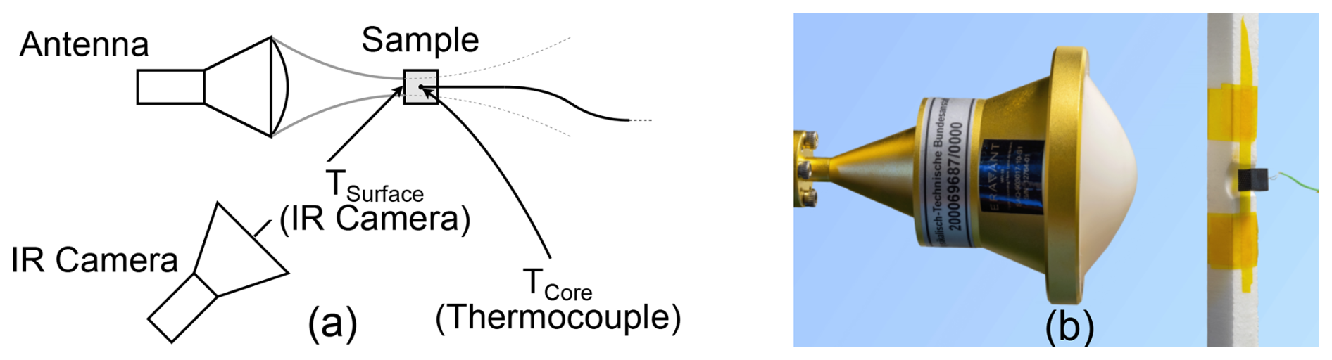
Figure 1Test setup for material heating (a) sketch illustrating the concept and (b) photograph of the setup.
Figure 2 shows the results of the heating experiment for the material Polyether Ether Ketone (PEEK) ESD 101 (Victrex Manufacturing Limited, 2023). This material exhibited significant heating in both surface and core temperatures, when exposed to a (CW) signal with 3.3 W at 92 GHz. This temperature increase is expected to be sufficient to trigger ignition in an explosive atmosphere. Additionally, it is highly machinable – an important factor for producing the number of samples required for the ignition tests. Further details on these measurements with various materials can be found in Walkemeyer et al. (2022b).
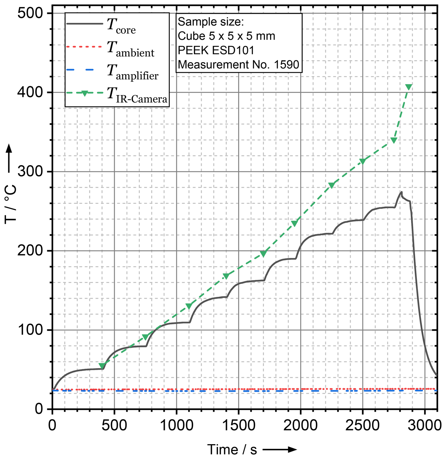
Figure 2Result for Polyether Ether Ketone ESD 101 exposed to a (CW) signal with a power of 3.3 W at 92 GHz in the heating experiment. The sample surface temperature, core temperature and the temperature of the amplifier and ambient temperature are shown.
For the ignition experiments presented in this work, cubic samples of PEEK ESD 101, with an edge length of 5 mm, were used.
2.2 Explosive gas-air atmospheres
Measurements are conducted using diethyl ether–air and carbon disulfide–air mixtures, selected based on their known low ignition temperatures from experience and previous research (Setchkin, 1954; Markworth and Schebsdat, 1985). For example, diethyl ether falls under temperature class T4 in explosion protection standards for electrical equipment, while carbon disulfide is classified under temperature class T6 in Chemsafe (2025), making these mixtures a reasonable choice for this worst-case experiment. Different percentages of the individual gas mixtures are used, starting with the stoichiometric concentration.
During the ignition tests, the cubic PEEK ESD 101 sample, with an edge length of 5 mm, is placed on a polytetrafluoroethylene (PTFE) holder and secured with a polyimide strap, held in place by a spring. The sample position and orientation is adjusted from outside the ignition vessel. A highly sensitive wire thermocouple is embedded inside the lossy sample to monitor its temperature. Additionally, the temperature in the ignition vessel is measured by mantle thermocouples at various positions. Initial tests revealed that there is no strong correlation between the sample's core temperature and ignition, indicating that the surface temperature significantly deviates from the core temperature. Therefore, in subsequent experiments, the thermocouple was positioned close to the sample's surface. Tests were conducted in both orientations shown in Fig. 3. In orientation (Fig. 3a), the thermocouple is positioned on the bottom surface, facing the antenna, while in orientation (Fig. 3b), it is placed on the surface facing away from the antenna.
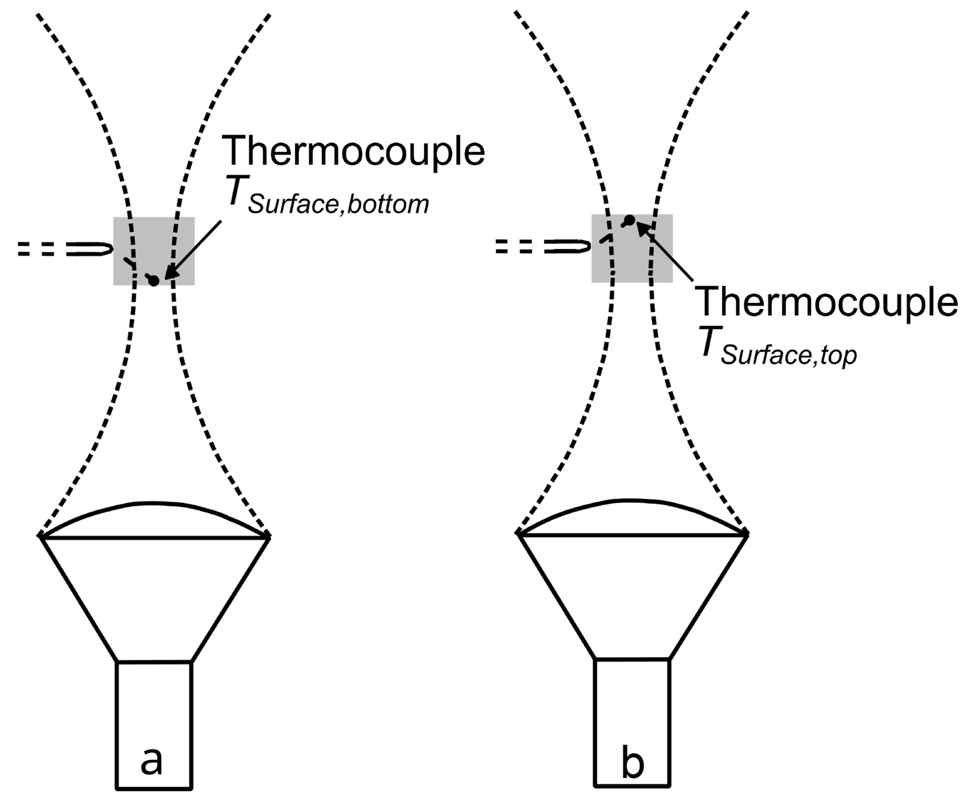
Figure 3Sketch of the sample with antenna and thermocouple (a) at the bottom surface of the sample and (b) at the top surface of the sample (Schierding et al., 2024).
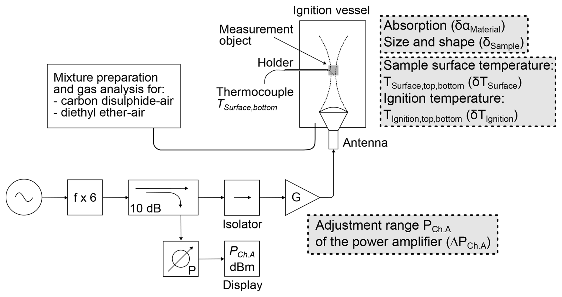
Figure 4Block diagram of the setup of the RF signal generation for the ignition tests on small hot components. Major uncertainty contributions are noted in grey boxes close to their origin in the test setup adapted from Schierding et al. (2024).
A block diagram of the ignition test setup, with a focus on RF signal generation, is shown in Fig. 4. A (CW-)signal with a frequency of 15.333 GHz is generated and then multiplied by a factor of 6 using a frequency multiplier yielding a signal at 92 GHz. A 10 dB coupler is included at this stage to monitor the RF power during the experiment. The signal is transmitted to the power amplifier via an isolator, and a highly focused lens horn antenna is directed at the sample from the bottom of the ignition vessel. During the ignition test, only the RF power before the isolator is known, and the tests are conducted at various power levels. After the experiment, the ignition test setup is disassembled allowing for a precise measurement of the power levels used during the experiments at the antenna input.
Figure 5 shows the experimental setup at the moment of ignition. The numbers in the figure are included to help explain the setup more clearly.

Figure 5The experimental setup in the moment of an ignition. The main components of the setup are: 1 – ignition vessel, 2 – RF-signal generation, 3 – frequency multiplier, 4 – power meter, 5 – signal generator, 6 – flammable liquid, 7 – mass flow controllers and heating system, 8 – gas analysis, and 9 – oximeter.
The ignition vessel, which contains the gas-air mixture and the sample at the center, is labeled one. The antenna is positioned at the bottom of the ignition vessel, just above label two. To the right of label two is the RF signal generation setup, which includes the power amplifier and other components, as shown in Fig. 4. The frequency multiplier is labeled three, and the power meter is marked as four. The RF signal generator is labeled five.
To prepare the gas-air mixture, the flammable liquid (labeled six) is utilized as the base component, with a pump located to its right controlling its flow. The mass flow controllers and heating system (labeled seven) collaborate with the pump settings to manage the evaporation of the flammable liquid. Once prepared, the gas mixture is introduced into the ignition vessel. Gas analysis units (labeled eight and nine) are connected to the ignition vessel via a secondary pipe, which remains open only until the gas-air mixture analysis is complete. Once the analysis is finished, this pipe is sealed to maintain the conditions within the ignition vessel for the experiment.
The experiments showed that it is easily possible with this setup to trigger an ignition by RF radiation at 92 GHz. The results using carbon disulfide in air as a explosive gas are summarized in Table 1.
Table 1Results for various vol % carbon disulfide in air at three power levels (Schierding et al., 2024). Sun symbol = ignition, crystal symbol = cold flame ignition, – = no ignition.
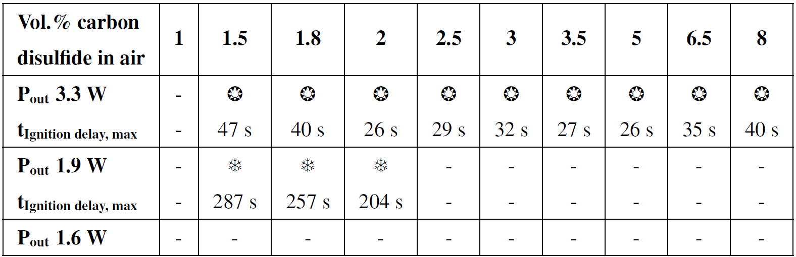
The most favorable gas-air mixture for ignition in this experiment is expected to be 1.8 vol % (Setchkin, 1954). With an RF power of 3.3 W, ignitions are obtained in the range from 1.5 vol % to 8 vol %. The ignition delay times vary from 26 to 47 s. At the power level of 1.9 W cold flame ignitions (Markworth and Schebsdat, 1985) are observed for 1.5 vol %, 1.8 vol % and 2 vol % only. These ignitions have significantly longer delay times, ranging from 204 to 287 s. These findings agree well with the expected most favorable gas-air mixture for ignition of 1.8 vol %. No ignitions were observed with an RF power of 1.6 W.
Figure 6 shows the measured surface temperatures of the sample at which ignition occurs. It is evident that the bottom surface, facing the antenna, reaches significantly higher temperatures than the top side, regardless of the RF power setting. At an RF power of 1.9 W, the ignition temperature remains approximately constant across the tested mixture concentrations. However, at 3.3 W, there are deviations in the ignition temperature that do not align with the expected ignition curve. According to literature (Setchkin, 1954; Markworth and Schebsdat, 1985), the ignition temperature is expected to increase with rising volume percentages of the mixture. In our experiments, we do not observe this effect. This may be caused by the faster and, therefore, less homogeneous heating of the absorber.
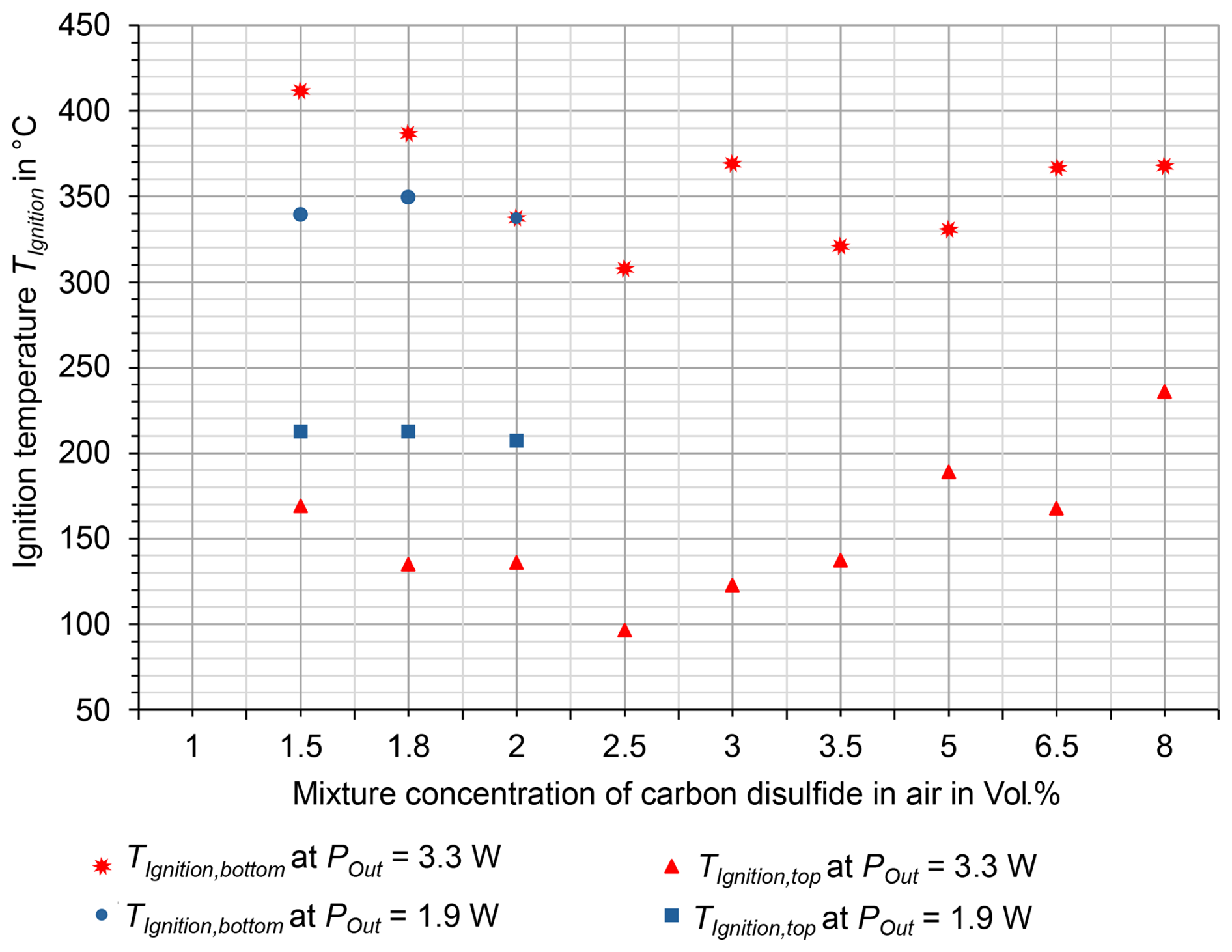
Figure 6Sample bottom and top surface temperatures at ignition for various vol % carbon disulfide in air at two RF power levels (Schierding et al., 2024).
At temperatures above 250 °C, the absorber visibly changes, showing bubbles and cracks on the surface, even if no ignition occurs during the experiment. To preserve samples and reduce time needed to mount the thermocouple, experiments using diethyl ether–air mixtures are stopped once the bottom surface temperature reaches 250 °C, as ignition temperatures are expected to be lower than this threshold. The most favorable diethyl ether–air mixture for ignition in this experiment is expected to be 23 vol % (IEC, 2017), Sect. 26.5.3.
Table 2Results for various vol % diethyl ether in air at two power levels with and without limited experimental run time (Schierding et al., 2024). Sun symbol = ignition, crystal symbol = cold flame ignition, – = no ignition.
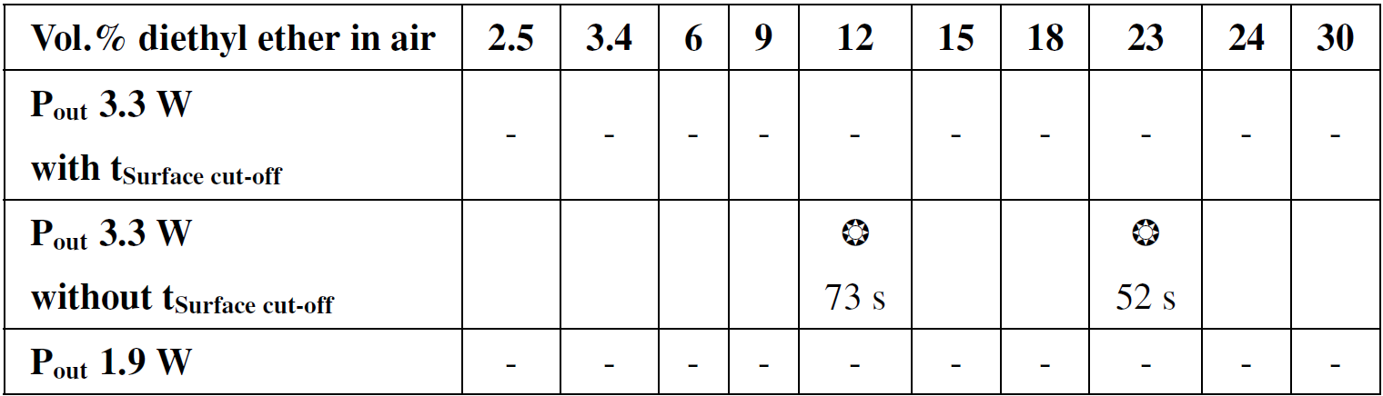
However, as shown in Table 2, no ignitions are observed when applying this stopping criterion. Therefore, two additional experiments at 23 vol % and 12 vol % are conducted, where the sample is intentionally destroyed. Ignitions are achieved after 52 s at a surface temperature of 290 °C for 23 vol %, and after 73 s at a surface temperature of 490 °C for 12 vol %. No ignitions are observed at an RF power of 1.9 W, regardless of the diethyl ether–air mixture volume percentage.
Thus, based on 124 ignition tests conducted and 32 ignitions observed, it was determined that no ignitions occurred at an antenna output power of Pout=1.6 W for carbon disulfide/air mixtures and at Pout=1.9 W for diethyl ether/air mixtures. Therefore, the resulting hot surfaces of the absorber do not act as an ignition source in this worst-case scenario.
To determine an RF power level for the safety limit, the results of the ignition tests in Sect. 3 and the material heating tests in Sect. 2 are considered.
5.1 Influences and Modelequation
To analyze the influences on the safety limit for RF radiation, a root cause analysis is performed.
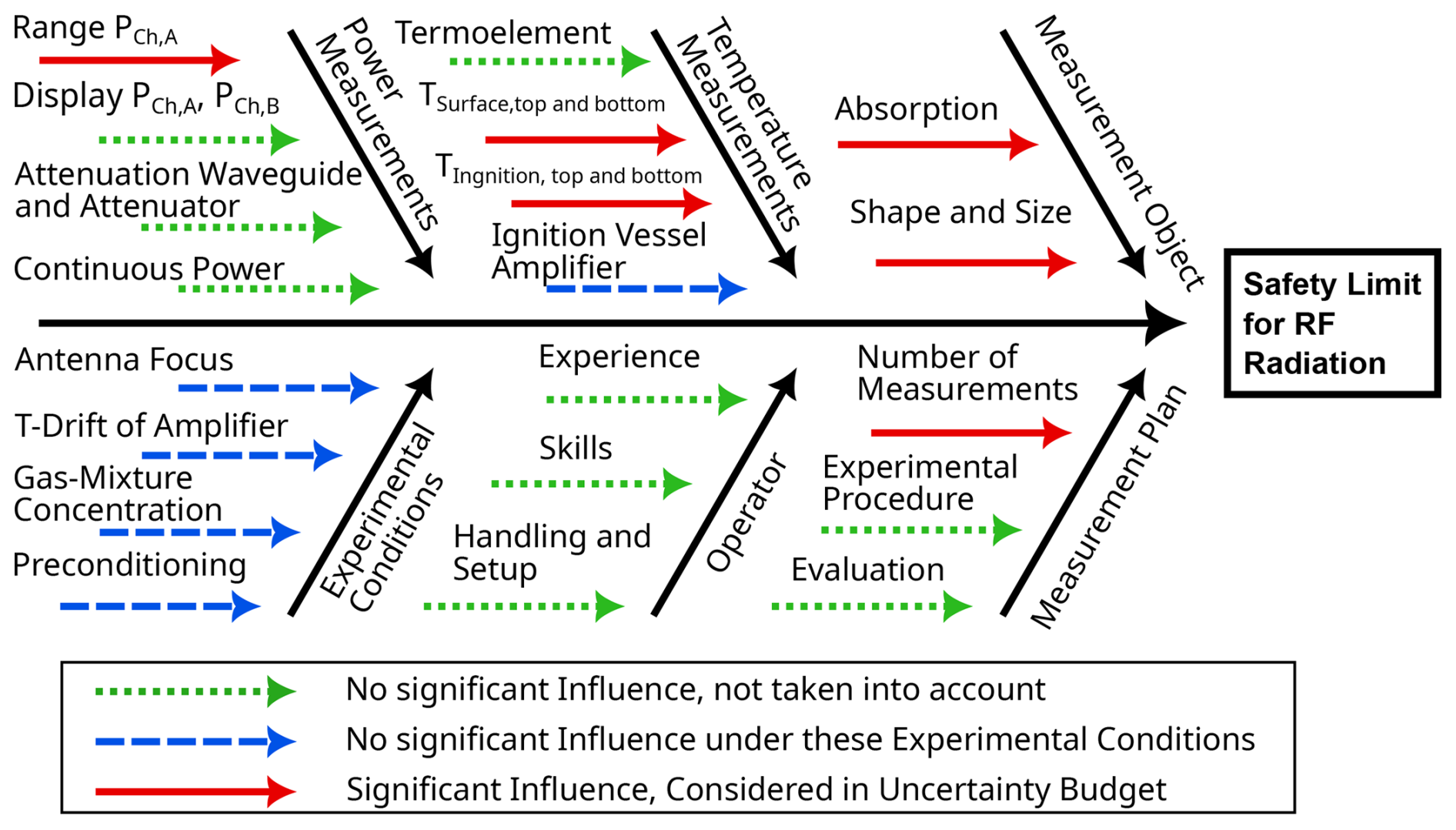
Figure 7Ishikawa diagramm showing the root cause analysis of the measurement error for the safety limit of the RF power.
In Fig. 7, all influences are detailed, grouped into categories, and ordered by their significance. The six main categories are power measurement, temperature measurement, the measurement object itself, the experimental conditions, the operator, and the measurement plan. These influence conditions are divided into three categories. Insignificant factors: Influencing factors that have no significant impact on measurement uncertainty are classified as irrelevant and marked with dotted arrows. An example of this is the influencing factors related to the experiment operator. Factors such as experience, skills, and handling of the setup can be controlled through training and familiarization and are therefore considered irrelevant. Insignificant influences under the specified conditions: Influencing factors that do not need to be included in the consideration of measurement uncertainty when certain specified conditions are met are marked dashed arrows. These include the focusing of the lens-horn antenna, the temperature drift (T-drift) of the power amplifier, the mixture concentration, the preheating of the test vessel, and the temperature measurements (ignition vessel, amplifier). Significant factors requiring consideration in measurement uncertainty analysis: Influencing factors marked with solid arrows that have a significant impact on measurement uncertainty must be included in the model equation. These include the adjustment range PCh.A of the power amplifier, the measured temperatures (TIgnition,top, TIgnition,bottom, TSurface,top, TSurface,bottom), the RF absorption, the shape and size of the measurement object, as well as the number of measurements performed. From these significant influencing factors a model equation for the safety limit for RF radiation is derived. For this purpose, the factors are divided into quantifiable influences Δ and non-quantifiable influences δ.
-
RF Power measurement: Adjustment range PCh.A of the power amplifier (ΔPCh.A).
-
Temperature measurement: Surface temperature of the sample on top and bottom sides (δTSurface), ignition temperature (δTIgnition).
-
Measurement object: Absorption capacity (δαMaterial), size and shape (δSample).
-
Measurement plan: Number of measurements (δn).
To illustrate and link the origin of the uncertainty to the test setup, the major contributions are shown in gray boxes near their respective sources in the test setup, as depicted in Fig. 4. The following quantities with a dashed arrow in Fig. 7 are not considered in the model equation, if they are maintained under specified conditions. This means that the measurement conditions and temperature measurements are continuously monitored during the experiments
-
Power amplifier: Control and monitoring of the temperature of the power amplifier and its temperature drift during the experiments through water cooling.
-
Ignition vessel: Adjustment and verification of the respective mixture concentrations and measurement of temperatures during the experiments.
-
Measurement object position: Verification of the focusing of the lens-horn antenna on the measurement object.
These considerations yield the model equation
Based on this equation, the result of the measurement uncertainty is determined using the GUM method (Joint Committee for Guides in Metrology, 2008) considering the influencing factors and their uncertainty contributions through Gaussian error propagation. The calculation is performed using the software GUM Workbench Pro (Metrodata, 2024).
This allows for the expression of the expanded measurement uncertainty with a coverage factor of k=2 and a coverage probability of 95 % with a normal distribution.
For the calculation, the corresponding types, distributions, and uncertainty contributions are assigned to the influencing factors. For the output power at the antenna Pout [W] (Eq. 1), a Type-A uncertainty is assigned, which is taken into account through the number of trials. The other quantities are incorporated into the model equation through Type-B uncertainties. Thus, the adjustment limits at 1.9 and 1.6 W at the input of the power amplifier are considered via a rectangular distribution through ΔPCh.A. Furthermore, the number of measurements Δn for each parameter combination of the ignition tests from Sect. 3 is included in the measurement uncertainty analysis with an uncertainty contribution of 30 % (empirical value). The absorption (approx. 90 %) of the absorber material used, PEEK ESD101, as the measurement object is taken into account via δαMaterial. Additionally, small manufacturing and experimental deviations in size and shape of the measurement object, δAMessobjekt, in the range of 5 %, as well as temperature deviations of δTSurface and δTIgnition in the range of 2 %, are also considered.
Based on the respective uncertainty contributions, the final result for the measurement uncertainty analysis is given in the form of
Additionally, the coverage probability and the coverage factor k are specified and verified.
5.2 Resulting safe RF power level
Based on the ignition tests with carbon disulfide-air mixtures and diethyl ether-air mixtures, it was determined that no ignition occurred at an antenna output power of Pout=1.6 W (see Sect. 3). With respect to this experimental limit, the following result of the measurement uncertainty analysis is obtained by applying the GUM method (Joint Committee for Guides in Metrology, 2008), the model Eq. (1), and the mentioned uncertainty contributions:
With a coverage factor of k=2 and a coverage probability of 95 % (normal distribution). Based on safety considerations, the antenna output power of Pout=1.6 W is reduced by the expanded measurement uncertainty U=0.71 W. In addition to considering the expanded measurement uncertainty, a safety factor of 10 % is applied. Therefore, the safety limit for RF (CW) radiation is given by PLimit=800 mW at 92 GHz.
Table 3Overview of power limits in explosive atmospheres for different frequency ranges.
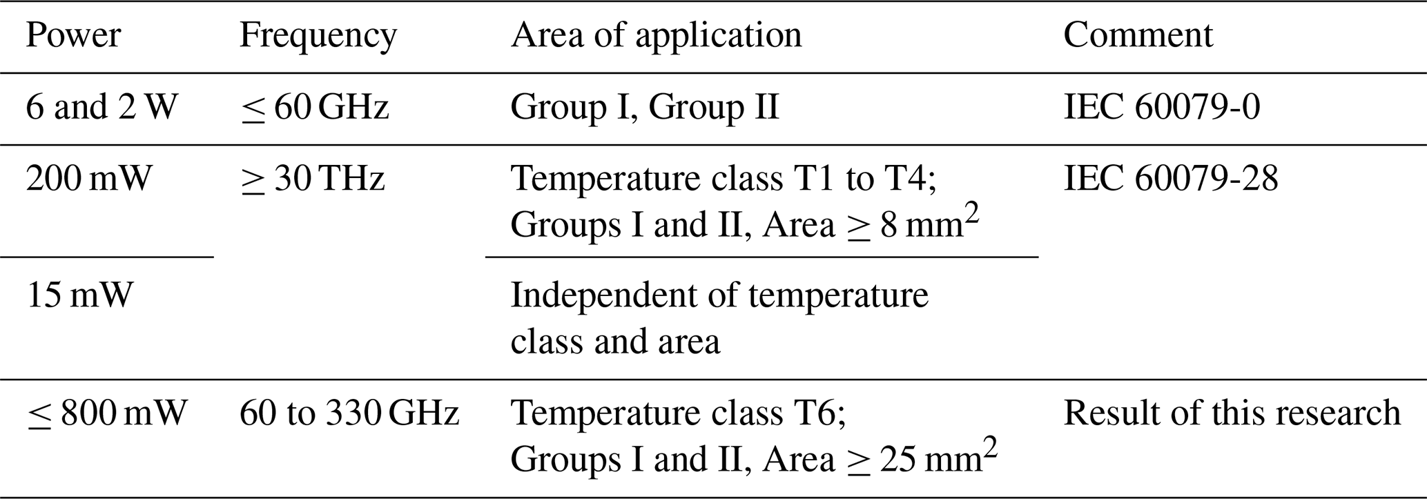
As shown in Table 3, this newly proposed safety limit aligns well with the 2000 mW limit for a maximum thermal initiation time of 20 µs specified in IEC (2017), which applies up to 60 GHz, and falls within the regulatory gap beyond this frequency. Above 30 THz, the determined limit is best compared to the 15 mW limit for radiated power in IEC (2015), which is valid for all types of gas mixtures regardless of the ignition properties. Differences arise from the fact that the radiation can be focused to different degrees in the different frequency ranges and can therefore heat different sized gas volumes beyond the critical conditions via the absorber.
In this paper, ignition tests were performed in a worst-case scenario to determine a safe limit for RF radiation at 92 GHz in explosive atmospheres. For this, material tests were conducted, and a suitable lossy material was selected to be used in ignition tests with varying concentrations of disulfide-air mixtures and diethyl ether-air mixtures. The measurements were evaluated, and an uncertainty analysis was performed, yielding a limit for safe (CW) RF power of 800 mW at 92 GHz. The limit values for RF power thresholds specified in IEC 60079-0 up to 60 GHz for the safe operation of wireless communication devices in potentially explosive atmospheres could be extended in the future based on the results of this work.
No additional datasets are associated with this publication; all relevant experimental data are presented and discussed in the paper.
FKHG wrote the manuscript, conducted the measurements, and contributed to the evaluation of RF metrology. CS conducted the measurements, performed the measurement uncertainty evaluation, and contributed to the manuscript. KK and MB planned the research, provided ideas, participated in discussions at every stage of the study, and contributed to the manuscript.
The contact author has declared that none of the authors has any competing interests.
Publisher's note: Copernicus Publications remains neutral with regard to jurisdictional claims made in the text, published maps, institutional affiliations, or any other geographical representation in this paper. While Copernicus Publications makes every effort to include appropriate place names, the final responsibility lies with the authors.
This article is part of the special issue “Kleinheubacher Berichte 2024”. It is a result of the Kleinheubacher Tagung 2024, Miltenberg, Germany, 24–26 September 2024.
The authors would like to thank the companies Endress+Hauser Se+Co. KG and VEGA Grieshaber KG for valuable discussions and input. We are also very grateful to Fraunhofer IAF for lending us a power amplifier that enabled the creation of the explosions. Additionally, the authors would like to thank ChatGPT-4 for spell-checking this manuscript.
This research has been supported by the the companies Endress+Hauser Se+Co. KG and VEGA Grieshaber KG.
This open-access publication was funded by the Physikalisch-Technische Bundesanstalt.
This paper was edited by Frank Gronwald and reviewed by two anonymous referees.
Babrauskas, V.: Ignition handbook – Principles and applications to fire safety engineering, fire investigation, risk management and forensic science, Fire Science Publishers; Issaquah, USA, ISBN 0-9728111-3-3, 2003. a, b
Beyer, M. and Markus, D.: Ignition of explosive atmospheres by small hot particles: Comparison of experiments and simulations, Sci. Technol. Energ. Ma., 73, 1–7, 2012. a
CEN/TC 305: Explosionsfähige Atmosphären – Explosionsschutz, Explosive atmospheres – Explosion prevention and protection – Part 1: Basic concepts and methodology; German version EN 1127-1:2019, DIN Media, https://doi.org/10.31030/3028476, 2019. a
Chemsafe: Database Forsafety Characteristics In Explosion Protection, Chemsafe, http://chemsafe.ptb.de (last access: 28 August 2025), 2025. a
Endress+Hauser: Micropilot FMR62B – 80 GHz Radarsensor, Tech. rep., Endress+Hauser (Deutschland) GmbH+Co. KG, https://www.de.endress.com/en/field-instruments-overview/level-measurement/Radar-Micropilot-FMR62B?t.tabId=product-overview&store_locale=en, last access: 28 August 2025. a
Hattwig, M. and Steen, H. (Eds.): Handbook of explosion prevention and protection, Wiley-VCH, ISBN 3-527-30718-4, 2004. a
IEC (International Electrotechnical Comission): IEC 60079-28: 2.0: IEC 60079-28 Explosive atmospheres – Part 28: Protection of equipment and transmission systems using optical radiation, Tech. rep., IEC – International Electrotechnical Comission, 2015. a, b
IEC (International Electrotechnical Comission): IEC 60079-0: 7.0: Explosive Atmospheres – Part 0: Equipment – General Requirements, Tech. rep., IEC – International Electrotechnical Comission, ISBN 9782832250655, 2017. a, b, c, d, e, f
Joint Committee for Guides in Metrology: Evaluation of Measurement Data – Guide to the Expression of Uncertainty in Measurement, Joint Committee for Guides in Metrology, Rep. JCGM 100:2008, https://doi.org/10.59161/JCGM100-2008E, 2008. a, b
Kazemipour, A., Hudlička, M., Yee, S.-K., Salhi, M. A., Allal, D., Kleine-Ostmann, T., and Schrader, T.: Design and Calibration of a Compact Quasi-Optical System for Material Characterization in Millimeter/Submillimeter Wave Domain, IEEE T. Instrum. Meas., 64, 1438–1445, https://doi.org/10.1109/TIM.2014.2376115, 2015. a
MacDonald, A. D.: Microwave Breakdown in Gases, John Wiley and Sons, Inc., https://archive.org/details/microwavebreakdo0000macd (last access: 28 August 2025), 1966. a
Markworth, D. and Schebsdat, F.: Zündverhalten kleiner heißer Bauteile in Explosionsfähiger Atmosphäre, PTB Bericht, PTB-W-25, https://lbsvz1.gbv.de/DB=24/SET=2/TTL=41/SHW?FRST=45 (last access: 28 August 2025), 1985. a, b, c
Metrodata: GUM Workbench Professional Version 2.4, Tech. rep., Metrodata GmbH, http://www.metrodata.de/ver24_en.html (last access: 28 August 2025), 2024. a
Schierding, C., Gellersen, F., Hau, M., Kuhlmann, K., Thedens, M., and Beyer, M.: Ignition tests in explosive atmospheres using absorption of High-Frequency Electromagnetic radiation based on tests of small hot components, 15th International Symposium on Hazards, Prevention, and Mitigation of Industrial Explosions, Naples, Italy, 10–14 June 2024, Zenodo, https://doi.org/10.5281/zenodo.12621001, 2024. a, b, c, d, e
Setchkin, N. P.: Self-Ignition Temperatures of Combustible Liquids, J. Res. Nat. Bur. Stand., 53, 2516, https://nvlpubs.nist.gov/nistpubs/jres/53/jresv53n1p49_a1b.pdf (last access: 28 August 2025), 1954. a, b, c
Simon, L. H., Meyer, L., Wilkens, V., and Beyer, M.: Ultrasonically triggered ignition at liquid surfaces, Ultrason. Sonochem., 22, 235–242, https://doi.org/10.1016/j.ultsonch.2014.06.009, 2015. a
VEGA Grieshaber KG: VEGAPULS 31, 58364-de-241113, Schiltach, Germany, https://www.vega.com/en-uk/products/product-catalog/level/radar/vegapuls-31 (last access: 28 August 2025), 2025. a
Victrex Manufacturing Limited: PEEK POLYMER ESD101, Tech. rep., VICTREX, https://www.victrex.com/en/downloads/datasheets/victrex-peek-esd101 (last access: 20 August 2025), 2023. a
Walkemeyer, P., Thedens, M., Beyer, M., and Damm, C.: Investigation of ignition hazards due to the absorption of high-frequency electromagnetic radiation by solids, gases and vapours, in: 14th International Symposium on Hazards, Prevention and Mitigation of Industrial Explosions, ISHPMIE, 11–15 July 2022, Braunschweig, Germany, https://doi.org/10.7795/810.20221124, 2022a. a
Walkemeyer, P., Thedens, M., Beyer, M., and Damm, C.: Using RF Measurement Techniques to Evaluate Ignition Hazards due to Dielectric Heating in Explosive Atmospheres, Kleinheubacher Tagung 2022, 27–29 September 2022, Miltenberg, Deutschland, 2022b. a
Welzel, M., Schenk, S., Hau, M., Cammenga, H. K., and Bothe, H.: Ignition of combustible air mixtures by small radiatively heated surfaces, J. Hazard. Mater., A72, 1–9, https://doi.org/10.1016/S0304-3894(99)00167-3, 2000. a
Welzel, M. M.: Entzündung von explosionsfähigen Dampf/Luft- und Gas/Luft-Gemischen durch kontinuierliche optische Strahlung, PhD thesis, TU Braunschweig, Physikalisch-Technische Bundesanstalt, PTB-Bericht W-67, Braunschweig, ISBN 389429812X, 1996. a