 | 04 Sep 2018
The response of nonlinearly loaded antennas to repetitive HPEM excitations as obtained from equivalent circuit models
Devanand Palur Palanivelu
Robert Michels
Matthias Kreitlow
Frank Gronwald
In this contribution the effects of repetitive pulse excitations on linearly and nonlinearly loaded antennas are studied on the basis of equivalent circuit models. In the known linear case, repetitive pulses can lead to an increase of the amplitudes of oscillations. These oscillations decay, if realistic quality factors are assumed, comparatively quickly. In the considered nonlinear case the effects of repetitive pulses can add up and persist along much larger time scales. This remarkable effect has no equivalent in the linear case.
- Article
(1249 KB) - Full-text XML
- BibTeX
- EndNote


While most models in EMC are linear (Lee, 1995; Tesche et al., 1997), the inclusion of nonlinear effects which are due to the presence of nonlinear electronic elements is of interest as well (Krauthäuser et al., 2002; Rambousky et al., 2014; Kotzev et al., 2016). The analysis of nonlinear models, however, is not straightforward since many field theoretical methods fail in the nonlinear case. It is then a common strategy to separate the problem in a linear and a nonlinear part, where the linear part mainly contains the field-theoretical information of the problem while the inclusion of the nonlinear part then leads to nonlinear but scalar equations that need to be solved by some method (Liu and Tesche, 1976; Sarkar and Weiner, 1976). On this basis, it has recently been shown how to reduce in an EMC context a nonlinear coupling problem to an equivalent circuit model which eventually can be simulated in an LTSpice environment (LTSpice, 2016) to obtain the solution of the nonlinear problem (Kotzev et al., 2017). This formalism will be used in this contribution to study the effect of repetitive rather than single excitations. It will be seen that in this case nonlinear effects can add up to yield larger responses if compared to the linear case.
In the following Sect. 2 the considered nonlinear setup and its equivalent circuit modeling is shortly reviewed. In Sect. 3 the effect of repetitive pulses on linear oscillating systems is analyzed while the nonlinear case is considered in Sect. 4.
To better illustrate the context of this work, Fig. 1 shows a measurement setup which allows exciting a linearly or nonlinearly loaded antenna within a metallic enclosure. The excitation is done by a TEM-field which may couple through aperture slots in the front plate into the enclosure. More details of this measurement setup can be found in Kotzev et al. (2016).
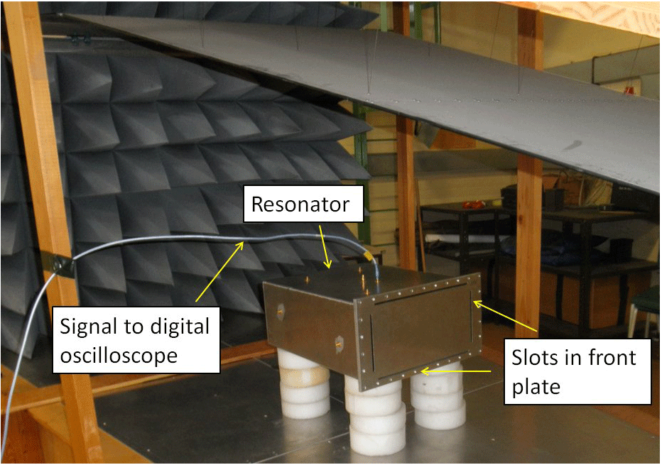
Figure 1Measurement setup that has been used in Kotzev et al. (2016) to experimentally observe transient responses to HPEM field excitation: A metallic enclosure resonator is positioned within an open TEM waveguide. The time domain response of an internal loop antenna within the resonator is measured via an adapter which leads to the outside of the enclosure.
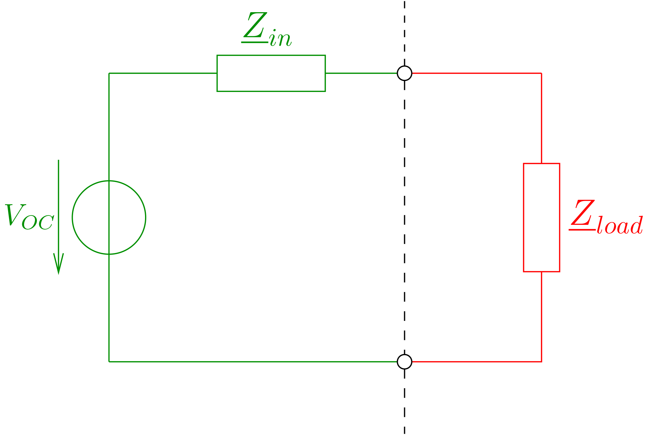
The measurement setup has been turned into a numerical model and into an equivalent circuit model as well (Kotzev et al., 2017). The basis of the equivalent circuit model is given by the model of a receiving antenna, as displayed in Fig. 2. It contains as important parameters the input impedance , which characterizes the antenna under consideration, and the open circuit voltage Voc which is determined by the excitation applied to the receiving antenna. Both parameters can be determined by either measurement or numerical simulation. As excitation, single HPEM pulses of a double-exponential form have been used in Kotzev et al. (2016). It then turned out that the resulting open-circuit voltage is of the form of a damped sinusoidal pulse, i.e., the used narrowband loop antenna is selective and mainly picks up a main resonance frequency from the exciting broadband double-exponential pulse. The load which is indicated in Fig. 2 as well can either be linear or nonlinear.
For a complete equivalent circuit model it is not sufficient to have the input impedance as measured or simulated data points. Rather, the input impedance should be given in terms of lumped circuit elements which approximate the input impedance over a certain frequency range. To determine these lumped circuit elements is a classical and nontrivial task, compare, for example (Streable and Pearson, 1981; Michalski and Pearson, 1984; Rambabu et al., 1999; Long et al., 2000; Adams et al., 2013). An equivalent circuit model of a loop antenna which has been used in the present context is shown in Fig. 3. It consists of elements L0 and C0 which characterize the low-frequency behavior of the antenna. Further parallel resonance circuits are added to account for either higher antenna resonances or resonances of the antenna environment, such as given by a metallic enclosure. In general, the presence of an enclosure, if compared to a free space situation, will modify the near field properties of the antenna, as exemplified by L0 and C0, and lead to additional resonances on which are superimposed the antenna resonances (Gronwald, 2006).
A Schottky diode is indicated in Fig. 3 as well. It contains as important parameters a parasitic capacitance and two parasitic resistors which model realistic losses. The Schottky diode is chosen because it is a standard circuit element which occurs in many applications. In addition, due to its parasitic capacitance it produces the desired nonlinear effect that will be discussed below.
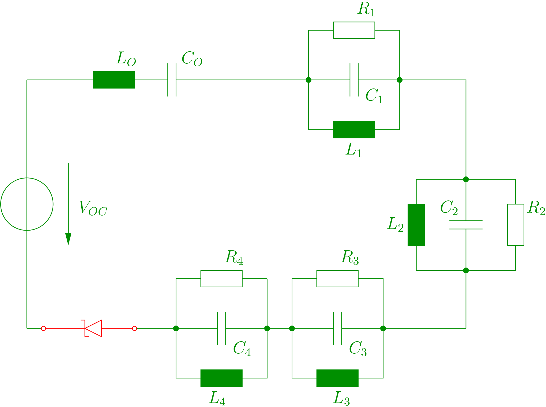
Figure 3Equivalent circuit model of a nonlinearly loaded loop antenna, as determined in Kotzev et al. (2017).
While the study of linear circuits is somewhat trivial it still provides some useful insights which are of interest in an EMC context. In view of equivalent circuit models we restrict ourselves in this section to the study of the excitation of single harmonic oscillators which are excited by damped sinusoidal pulses. As already mentioned, the damped sinusoidal pulses result as open circuit voltages from the original double exponential pulses which excite the considered loop antennas.
The voltage UC across the capacitor of a simple RLC-circuit, excited by an external voltage V, is given by
which can be written in the form
A damped sinusoidal pulse is chosen as an input signal,
with the resonating frequency of the given RLC-circuit. With the further abbreviation one gets
The solution of such an ordinary second order differential equation is a standard procedure which does not need to be repeated here. For illustration we choose values L=53.1nH, C=1.1pF, R=0.219Ω, V0=1450V, β=108/s and obtain for boundary conditions V and V s−1 a solution which is displayed in Fig. 4.
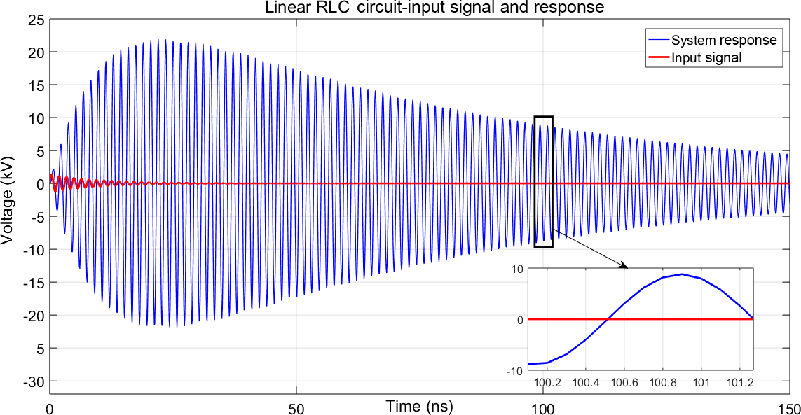
Figure 4Input Signal V and system response UC of a linear RLC-circuit with a single damped sinusoidal pulse as excitation. In this example it is clearly seen that the response is much larger if compared to the original excitation.
Turning to repetitive pulses, the same differential equation (Eq. 1) can be used for the analysis. In general, the voltage may still be oscillating when a consecutive pulse hits the system. Then the resulting voltage depends on the initial conditions which are given by UC and its derivative at the time when the consecutive pulse arrives. It turns out that consecutive pulses may support or counteract each other. To illustrate this, the following four combinations of initial conditions are considered:
-
Case 1: UC= at a positive maximum and
-
Case 2: UC= at a negative maximum and
-
Case 3: UC=0 and at a positive maximum
-
Case 4: UC=0 and at a negative maximum
The solutions for these cases are shown in the next Figs. 5 to 8. It is seen that in case 1 the second pulse leads to a smaller response if compared to the first response, i.e., the pulses are counteracting. In case 2 an additive effect is observed. Cases 3 and 4 lead to responses where the effects of the second pulses are inbetween case 1 and case 2 and lead to a minor increase in amplitude.
Figure 5System response due to two pulses according to case 1. The response due to the second pulse counteracts the existing response, there is a reduction in magnitude of the response after the second pulse.
Figure 6System response due to two pulses according to case 2. The response due to the second pulse supports the existing response, there is an increase in magnitude of the response after the second pulse.
Figure 7System response due to two pulses according to case 3. The response due to the second pulse supports the existing response, however, there is no considerable increase in magnitude of the response after the second pulse.

Figure 8System response due to two pulses according to case 4. The response due to the second pulse supports the existing response, however, there is no considerable increase in magnitude of the response after the second pulse.

In summary, it is seen that in the linear case the effect of repetitive pulses can straightforwardly be analyzed. To achieve additive effects, i.e., increasing system responses, it is important to have consecutive pulses arriving at appropriate times such that following pulses do not counteract. In practice, this might not be easy to achieve. Also, of course, additive effects can be achieved only as long as a previous oscillation is present and not already decayed when a subsequent pulse arrives.
To approach the nonlinear case and in view of Fig. 3, the realistic model of a Schottky diode now is added to the RLC-circuit. In contrast to the linear case, a purely analytical analysis is no longer feasible. Therefore the network solver LTSpice is used which is capable of numerically solving the relevant circuit equations (LTSpice, 2016). The corresponding model is shown in Fig. 9. The included voltage source can be any time domain signal, such as the previously used damped sinusoidal excitation given by Eq. (3).

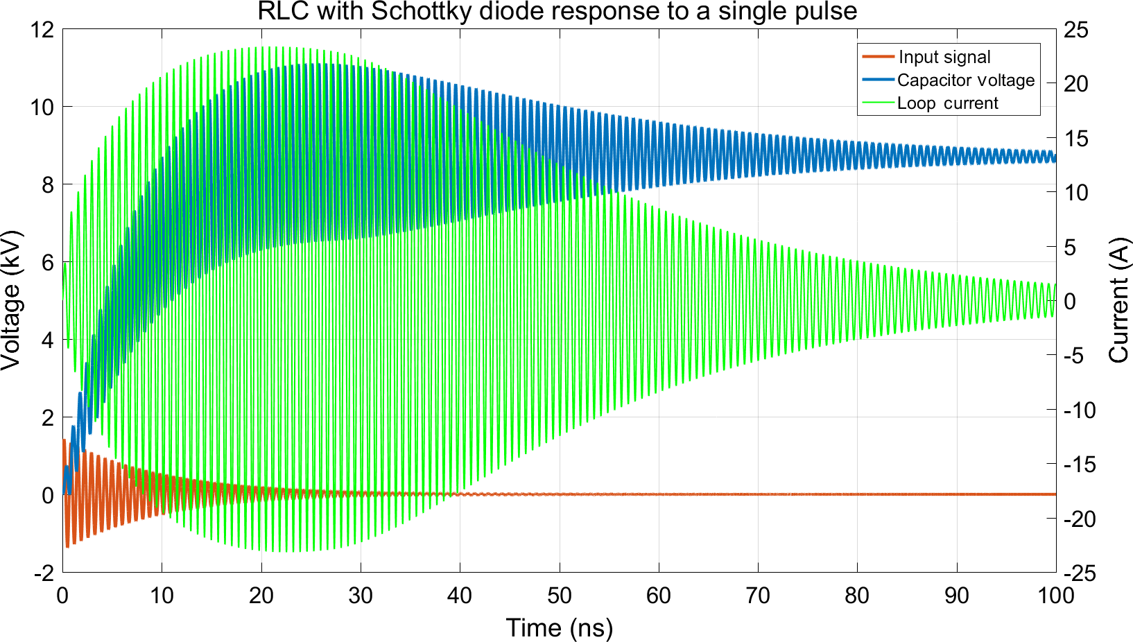
The application of a single damped sinusoidal pulse, with the same parameters as in the linear case, leads to the response shown in Fig. 10. Similar to the phenomena already observed in Kotzev et al. (2016, 2017), a considerable DC-contribution appears which indicates the storage of electric energy in the system.
Applying two subsequent pulses leads to the response shown in Fig. 11. It is interesting to observe that an additive effect clearly is visible. In contrast to the linear case it is neither required to have the second pulse to arrive at a specific time to meet proper initial conditions nor to have a previous oscillation in the system. The duration of the DC part is longer than the duration of the damped oscillatory response and it is the DC part which adds up.
Within the LTSpice environment it is easy to also analyze the effect of multiple pulses. In Fig. 12 the response to 17 subsequent pulses is shown. Now it is observed that the additive effect converges and is limited according to the charging curve of a capacitor. Nevertheless, the voltage achieved is at least comparable to the linear case and not limited in time to the duration of the oscillation of a single system response.
Equivalent circuit modeling is useful to analyze the response of nonlinear systems to repetitive excitations in an EMC context. In this study it has been shown that repetitive pulses can produce additive effects within system responses, both in the linear and nonlinear case. In the linear case an increasing response considerably depends on the time interval inbetween subsequent pulses since a following pulse may counteract the action of its predecessor. Also the duration of an additive effect is bound to the duration of oscillation which, in turn, depends on the quality factor of the system. In contrast to this, a nonlinear configuration can produce a DC part in the system response which is of a much longer duration and not limited to the duration of an oscillation. This DC part can be increased by subsequent pulses without taking particular care of initial conditions or time intervals.
The data presented in this article are available from the authors upon request.
Basically, this is a common work where DPP and RM did most of the simulations and modelling, and MK and FG contributed main ideas.
The authors declare that they have no conflict of interest.
This article is part of the special issue “Kleinheubacher Berichte 2017”. It is a result of the Kleinheubacher Tagung 2017, Miltenberg, Germany, 25–27 September 2017.
The research work was funded by the Bundeswehr Research Institute for
Protective Technologies and NBC Protection with contract number
E/E590/HZ004/AF119.
Edited by: Frank Sabath
Reviewed by: Frank Leferink and one anonymous referee
Adams, J., Jacob, J., and Bernhard, J.: Broadband equivalent circuit models for antenna impedances and fields using characteristic modes, IEEE Antennas Propag., 61, 3985–3994, 2013. a
Balanis, C. A.: Antenna theory: analysis and design, John Wiley & Sons, 3rd edition, 2005. a
Gronwald, F.: Antenna Theory in Resonating Systems derived from Fundamental Electromagnetism, Res. Electrica Magdeburgenses, 16, Habilitation Thesis, ISBN: 3-929757-93-1, 2006. a
Kotzev, M., Kreitlow, M., and Gronwald, F.: Transient Excitation of Nonlinearly Loaded Resonators and Observation of System Responses in Time Domain, Proc. of EMC Europe 2016, Wroclaw, Poland, 75–78, September 2016. a, b, c, d, e
Kotzev, M., Bi, X., Kreitlow, M., and Gronwald, F.: Equivalent circuit simulation of HPEM-induced transient responses at nonlinear loads, Adv. Radio Sci., 15, 175–180, https://doi.org/10.5194/ars-15-175-2017, 2017. a, b, c, d
Krauthäuser, H. G., Tkachenko, S., and Nitsch, J.: The Action of Non-Linear Effects in a Resonator, Proc. of the XXVIIth General Assembly of the International Union of Radio Science, URSI GA 2002, Maastricht, the Netherlands, 4 pp., August 2002. a
Lee, K. S. H. (Ed.): EMP Interaction: Principles, Techniques, and Reference Data, revised printing, Taylor & Francis, Washington D.C., 1995. a
Liu, T. K. and Tesche, F. M.: Analysis of antennas and scatterers with nonlinear loads, IEEE Antennas Propag., 24, 131–139, 1976. a
Long, B., Werner, P., and Werner, D.: A simple broadband dipole equivalent circuit model, Antennas and Propagation Society International Symposium, Vol. 2, IEEE, 2000. a
LTspice: Linear Technology, LTspice IV, Linear Technology, available at: http://www.linear.com/designtools/software/ (last access: 26 July 2018), 2016. a, b
Michalski, K. and Pearson, L.: Equivalent circuit synthesis for a loop antenna based on the singularity expansion method, IEEE Antennas Propag., 32, 433–441, 1984. a
Rambabu, K., Ramesh, M., and Kalghatgi, A. T.: Broadband equivalent circuit of a dipole antenna, IEE P.-Microw. Anten. P., 146, 391–393, 1999. a
Rambousky, R., Tkachenko, S., and Nitsch, J.: A novel solution algorithm for nonlinearly loaded transmission lines inside resonating enclosures, Adv. Radio Sci., 12, 135–142, https://doi.org/10.5194/ars-12-135-2014, 2014. a
Sarkar, T. K. and Weiner, D. D.: Scattering Analysis of Nonlinearly Loaded Antennas, IEEE Antennas Propag., 24, 126–131, 1976. a
Streable, G. W. and Pearson, L. W.: A numerical study on realizable broad-band and equivalent admittances for dipole and loop antennas, IEEE Antennas Propag., 29, 707–717, 1981. a
Tesche, F. M., Ianoz, M. V., and Karlsson, T.: EMC Analysis Methods and Computational Methods, John Wiley & Sons, New York, 1997. a
- Abstract
- Introduction
- Review of measurement setup and equivalent circuit modeling
- The linear case for single and repetitive excitations
- The nonlinear case for single and repetitive excitations
- Conclusions
- Data availability
- Author contributions
- Competing interests
- Special issue statement
- Acknowledgements
- References