Using The Kramers-Kronig Transforms To Retrieve The Conductivity From The Effective Complex Permittivity
Ludger Klinkenbusch
While measuring the effective permittivity of dispersive material it may be of interest to distinguish between conductivity losses (caused by free electrons) and dielectric losses (caused by bounded electrons) which both are included in the imaginary part. This usually turns out to be a non-trivial task unless suitable dispersion models for the dielectric and/or the conductivity properties of the material are assumed. In this paper we present a more general method based on the Kramers-Kronig transformations to separate the conductivity from the effective complex permittivity of a dispersive material. The Kramers-Kronig transforms (or KK-transforms) are unique integral relations between the real and the imaginary part of a complex quantity describing a causal system. The proposed method and the corresponding algorithm are tested by first supposing some fictitious values of the complex permittivity satisfying the KK-transforms. Then, different values of a conductivity are added leading to a change of the imaginary part of the effective permittivity while the real part remains the same. The effective permittivity (including a conductivity part) does generally not satisfy the KK-transforms. This fact will be employed to retrieve the conductivity from that effective complex permittivity. Finally the method is applied to measured values found in the literature to retrieve the conductivity from the effective permittivity of composite material.
- Article
(721 KB) - Full-text XML
- BibTeX
- EndNote
In electrical engineering the dispersion phenomenon is well-known as a frequency-dependent variation of the phase velocity of electromagnetic waves due to specific material properties. Dispersion occurs in any medium which is not vacuum though its effect can often be neglected within a properly limited frequency band. Dispersion is closely related to the causality principle meaning that a cause can never happen after the corresponding effect. Kramers (1927) showed that the real part of the refractive index (closely related to the real part of the complex permittivity) of an optical system can be calculated from the absorbed light, i.e. from the imaginary part of the complex permittivity. Kronig (1926) proved that the dispersion in a medium is a direct consequence of the causality principle. The Kramers-Kronig (KK) transforms generally relate the real and the imaginary parts of a complex quantity describing a causal system. In other words, the real part can be uniquely calculated from the imaginary part and vice versa. However, there are some constraints for any complex quantity to satisfy the KK-transforms such as stability and linearity (Esteban and Orazem, 1991; Macdonald and Urquidi-Macdonald, 1990, 1985). Macdonald and Urquidi-Macdonald (1990) suggested that these relations can be employed to resolve the complex impedance data of any electrochemical system. They proved that the electrical equivalent circuit of any electrochemical impedance should follow the KK-transforms provided that it satisfies the aforementioned constraints.
In practice, the main difficulty in numerically solving the KK-transforms is the indefiniteness of the integrals whereas the available data are given on a limited frequency range only. Several algorithms were proposed to overcome this problem by either calculating the data sets below the lowest available frequency to force the system to satisfy the KK-transforms (Esteban and Orazem, 1991), by extrapolating the experimental data over a wide frequency range (Boukamp, 1995; Macdonald and Urquidi-Macdonald, 1990), or by accordingly applying Fourier transform techniques (Collocott, 1977). In Wallace (1993) the question was discussed whether the Kramers-Kronig relationships place severe limitations on the bandwidths that can be achieved in homogeneous microwave absorbing materials.
We propose a systematic method that exploits the KK-transforms to distinguish between dielectric and conductive losses, i.e., to retrieve the conductivity from a given effective permittivity. Usually the imaginary part of the measurement of the complex permittivity includes both, dielectric losses and conductivity losses. However, the KK-transforms between the real and imaginary parts of the effective permittivity are satisfied only if the imaginary part does not contain any conductivity. The proposed method exploits that fact while two different strategies are possible: We numerically perform the KK-transform on the given (i.e. measured) real part to find find the corresponding imaginary part which is solely due to dielectric losses. The difference between that KK-transformed imaginary part and the given (measured) imaginary part must be due to the conductivity losses. A second approach is to numerically perform a KK-transform on the measured imaginary part. If it does not fit the measured real part, we conclude that there is some conductivity which can be found by solving a corresponding integral equation. To check the algorithm used in this paper, we will start from some fictitious values of the complex permittivity and of the conductivity. Afterwards, the method will be applied to real-world data (measured data found in the literature) of the effective permittivity of composite material.
3.1 Kramers-Kronig transforms and effective permittivity
The Ampere-Maxwell equation associates the magnetic field intensity to the time-derivative of the electric flux density and the electric current density according to
Within a linear homogeneous medium and are related to the electric field intensity by the causal convolutions
where ε0 is the permittivity of vacuum, represents the relative permittivity, and denotes the electric conductivity. Note that dielectric effects including dielectric losses are part of . We apply the Fourier transform defined as
and
In general, both of the frequency-domain (Fourier-transformed) material parameters εr and σ are complex-valued. However, in practice the conductivity is assumed to remain real-valued within a limited frequency range. In this paper we will use that assumption as well. Moreover, the real and imaginary parts of the complex relative permittivity can not be chosen independently. Since εr(ω) represents the Fourier transform of a causal function [i.e. for t<0, which also is reflected in the lower integral bound in Eq. (2)] its Fourier transform must be an analytic function of ω in the upper half complex-plane (Sethuraman and Sirohi, 1979). Equivalently, the real and imaginary parts of εr(ω) satisfy the KK-transforms, also known as the Hilbert transform.
With the definition
the Kramers-Kronig transforms are given by the integrals (Sethuraman and Sirohi, 1979)
where ψ also represents the angular frequency. Now we insert Eqs. (6) and (7) into (5) and obtain
In Eq. (12) we have introduced the effective relative permittivity as
For a real-valued conductivity σ, the real component of the effective relative permittivity is identical to the real component of the relative permittivity while the imaginary component contains both, dielectric and conductivity losses:
We insert Eq. (16) into (9) and (15) into (10) and derive:
A comparison of Eq. (17) with (9) and of (18) with (10) reveals that the real and imaginary parts of the effective relative permittivity satisfy the KK-transforms only if there is no electric conductivity, σ(ω)≡0. However, the results in Eqs. (17) and (18) also offer two methods to separate the electric conductivity for the commonly measured values of the effective relative permittivity:
- a.
Starting from Eq. (17) we perform a KK-transform on the measured values of . Subtracting from the result equals the last term in Eq. (17) yielding an integral equation for σ(ω).
- b.
Starting from Eq. (18), performing a KK-transform on the measured values of and subtracting the result from we directly obtain the conductivity σ(ω).
3.2 Numerical evaluation of the Kramers-Kronig transforms
Basically the KK transforms can be applied if the real or the imaginary part of the complex relative permittivity is known over the entire angular frequency range . However, generally the measured permittivity is available only on a limited frequency range which we assume as . Generally, from the denominator in the KK-transform integrands (ψ2−ω2) it follows that the result at an angular frequency ω is more reliable if ω is not too close to ωmin and ωmax. There are several strategies to cope with the problem of indefiniteness of the KK-integrals. Exemplarily we will treat the transform given in Eq. (10). Urquidi-Macdonald et al. (1990) and Lovell (1974) suggested to first divide the semi-infinite range of integration according to:
The first and the last integrals in Eq. (19) are neglected which is equivalent to the assumption the ε′ is constant in these domains:
As mentioned above the quality of the transformations is increased if the distance between the desired ω to each of the limits of the integral () is chosen to be large (Lovell, 1974). To this end, the permittivity ε′(ω) is extrapolated over a wider frequency range () according to
while the integration in Eq. (20) is performed on the interval () (Urquidi-Macdonald et al., 1990). Esteban and Orazem (1991) suggested a logarithmic extrapolation, Macdonald and Urquidi-Macdonald (1990) proposed a polynomial extrapolation. However, they found that a single high-order polynomial expansion leads to nonphysical oscillations at the ends of the extrapolation domains leading to significant errors in the numerical evaluation. In this paper we therefore use a spline approximation and extrapolation, i.e., we split the interval () into K sub-domains and expand the permittivity in the kth sub-domains using low-order polynomials according to
We insert Eq. (21) into (20) and obtain
A typical scheme is a division into 3–5 sub-domains and polynomials of degree 3–8.
4.1 Check of consistency
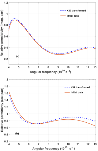
Figure 1Imaginary part (a) and real part (b) of the complex relative permittivity of a (fictitious) material without conductivity losses. From the initial data (red solid curve in (a)) the red solid curve (initial data) in (b) has been obtained using Eq. (9). From this result the blue broken curve in (a) and from this the blue broken curve in (b) have been obtained using Eq. (10) and again Eq. (9), respectively.
We start with a check of the self-consistency of the proposed method. The red solid curve in Fig. 1a) represents a fictitious imaginary part of the complex permittivity (σ=0). The corresponding real part of the complex permittivity (red solid curve in Fig. 1b) has been evaluated using a numerically performed KK-transform Eq. (9). The outcome has been numerically KK-transformed using Eq. (10) (blue broken curve in Fig. 1a) and finally again back transformed applying Eq. (9) (blue broken curve in Fig. 1b).
We observe that the data obtained for the imaginary part of the relative permittivity obtained after two KK-transforms relatively well fits the initial data. Even the three-times KK-transformed real part shows a reasonable agreement apart from a deviation at the end of the observation interval.
4.2 Conductivity retrieval
Now we add some conductivity to the previously defined fictitious material.We distinguish two cases:
- a.
frequency-independent conductivity σ=0.8 S m−1 with
- b.
frequency-dependent conductivity σ(ω) with .
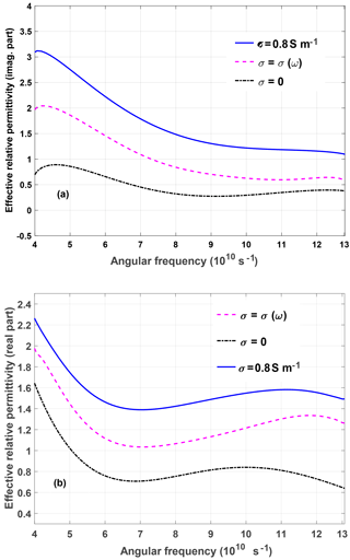
Figure 2Imaginary part of the effective complex permittivity for different values of the conductivity (a). The curves in (b) represent the corresponding Kramers-Kronig transforms according to Eq. (9). Note that only the curve for σ=0 (black solid) in (b) represents the correct real part of the effective complex permittivity for all conductivities.
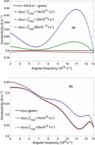
Figure 3Conductivity retrieval for a frequency-independent (a) and frequency-dependent (b) conductivity added to a dispersive material as described in Fig. 2. The retrieval is performed for different values of the upper bound , while s−1.
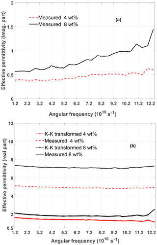
Figure 4Imaginary part (a) and real part (b) of the effective permittivity of different CNT composite materials as investigated in (Wang and Guang-Lin, 2013). In addition, the KK-transform Eq. (9) has been applied to the imaginary parts and compared to the measured real parts (b).
The situation is shown in Fig. 2. Clearly, only is changed by adding some (real-valued) conductivities. The imaginary part of the effective relative permittivity is shown in Fig. 2a for the different values of σ. Performing the KK-transform Eq. (9) on the curves in Fig. 2a yields different real parts as shown in Fig. 2b. However, the correct real part in Fig. 2b is only found for the KK-transform according to Eq. (9) in the case σ=0. In other words, only the real and imaginary parts of the complex permittivity without conductivity losses satisfy the KK-transforms.
Now we use Eq. (18) to retrieve the conductivities for the two cases described above.
In Fig. 3 the results of the conductivity-retrieval are shown for a frequency-independent (Fig. 3a) and frequency-dependent (Fig. 3b) conductivity added to a dispersive material as described in Fig. 2. The retrieval is performed for different values of the upper bound , while s−1. Obviously the bounds of the extrapolation domains have to be chosen properly to obtain satisfactory results.
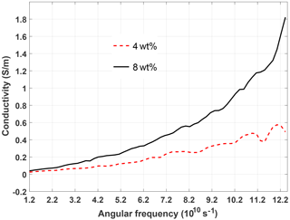
Figure 5Conductivity retrieved by the proposed method from the measured values of the effective permittivity of different CNT composite materials. The measured values were found in Wang and Guang-Lin (2013).
Finally, we applied the proposed method to investigate some measured values of the effective permittivity which is found in the literature (Wang and Guang-Lin, 2013). Here, carbon nano-tubes (CNT) in epoxy-resin multi-layers were composed at different CNT weight fractions (wt %) for designing an electromagnetic absorber in the frequency range 2–20 GHz. The effective permittivity was calculated from measurements of the reflection and transmission coefficients.
Figure 4 shows the imaginary part (Fig. 4a) and the real part (Fig. 4b) of the effective permittivity. We applied the KK-transform Eq. (9) to the imaginary part and obtained the curves additionally shown in Fig. 4b. As they do not agree with the measured values of the real part of the effective permittivity we conclude that the material includes conductivity losses. The corresponding conductivity which has been retrieved using Eq. (18) is represented in Fig. 5 for the two materials.
We introduced a systematic method to retrieve the electric conductivity from given values of the effective permittivity using Kramers-Kronig relations. The method has been applied to fictitious values of the complex permittivity and also to real-life data for a carbon nano-tubes composite material used for absorbers. The most crucial task in this method is the numerical evaluation of the Kramers-Kronig integrals. Therefore, future work will focus on the further investigation of related strategies including to find an a-priori estimate of the corresponding error.
The data are available from the authors upon request.
The authors declare that they have no conflict of interest.
The responsibility for the content of this publication is with the authors.
This article is part of the special issue “Kleinheubacher Berichte 2017”. It is a result of the Kleinheubacher Tagung 2017, Miltenberg, Germany, 25–27 September 2017.
This work was supported by the Deutscher Akademischer Austauschdienst (DAAD)
and the Egyptian Ministry of Higher Education and Scientific Research within
the GERLS framework.
Edited by: Thomas
Eibert
Reviewed by: Volkert Hansen and one anonymous referee
Boukamp, B. A.: A linear Kronig-Kramers transform test for immittance data validation, J. Electrochem. Soc., 142, 1885–1894, 1995. a
Collocott, S.: Numerical solution of Kramers-Kronig transforms by a Fourier method, Comput. Phys. Commun., 13, 203–206, 1977. a
Esteban, J. M. and Orazem, M. E.: On the application of the Kramers-Kronig relations to evaluate the consistency of electrochemical impedance data, J. Electrochem. Soc., 138, 67–76, 1991. a, b, c
Kramers, H. A.: La diffusion de la lumiere par les atomes, 2, Atti del Congresso Internationale dei Fisici, Como, 1927. a
Kronig, R. d. L.: On the theory of dispersion of x-rays, Journal of the Optimcal Society of America, 12, 547–557, 1926. a
Lovell, R.: Application of Kramers-Kronig relations to the interpretation of dielectric data, J. Phys. C Solid State, 7, 4378–4384, 1974. a, b
Macdonald, D. D. and Urquidi-Macdonald, M.: Application of Kramers-Kronig transforms in the analysis of electrochemical systems I: Polarization resistance, J. Electrochem. Soc., 132, 2316–2319, 1985. a
Macdonald, D. D. and Urquidi-Macdonald, M.: Kramers-Kronig transformation of constant phase impedances, J. Electrochem. Soc., 137, 515–517, 1990. a, b, c, d
Sethuraman, J. and Sirohi, R.: Dispersion relations in Fraunhofer diffraction, JOSA, 69, 907–909, 1979. a, b
Urquidi-Macdonald, M., Real, S., and Macdonald, D. D.: Applications of Kramers–Kronig transforms in the analysis of electrochemical impedance data III. Stability and linearity, Electrochim. Acta, 35, 1559–1566, 1990. a, b
Wallace, J. L.: Broadband magnetic microwave absorbers: Fundamental limitations, IEEE T. Magn., 29, 4209–4214, 1993. a
Wang, Z. and Guang-Lin, Z.: Microwave absorption properties of carbon nanotubes-epoxy composites in a frequency range of 2–20 GHz, Open Journal of Composite Materials, 3, 17–23, 2013. a, b, c


