 | 04 Sep 2018
Crosstalk Cancellation in Inductively Coupled Full-Duplex Data Transfer Systems by a single Multipole Dualport Coil Structure
Christian Schmidt
Martin Buchholz
Madhukar Chandra
Short range inductive data transfer has become very popular in the last years with the increased interest in technologies like RFID and NFC. Additionally, wireless power transfer has been a field of intensive research and product development. In industrial applications, a combination of both is often needed to replace mechanical contacts, mainly for safety and reliability reasons, especially regarding spark prevention and maintenance reduction.
In this paper, we present a compact inductive structure that can be implemented in an existing wireless energy transfer system. The structure is developed by field considerations, leading to a single structure comprising two signal ports that are decoupled from each other, but can be used to transfer a signal to a second structure of that kind with very small interference. An optimisation to achieve comparable channel characteristics is conducted by using 3-D field simulations. Subsequent measurements are conducted to verify the achieved performance.
- Article
(1937 KB) - Full-text XML
- BibTeX
- EndNote


In a current research project, our goal is to develop an inductively coupled full-duplex data transfer system to be be implemented in an existing wireless power transfer system. Due to the given size of the power transfer system, the data coupling structure needs to be compact while achieving good crosstalk performance to enable full-duplex data transfer in the range of tens of megabit per second. Especially the near-end crosstalk (NEXT) is an important measure in this application, as the two sides of the transfer system have both a transmit and a receive path that can easily interact with each other due to their close proximity. Nevertheless, also the far-end crosstalk (FEXT) can significantly decrease the link quality.
A way to deal with this problem is presented in the following chapters. The structure presented makes it possible to implement a full-duplex data transfer system with low crosstalk by shaping the magnetic field distribution to achieve a good decoupling of two channels.
A conducting loop carrying a current I creates a magnetic field in the surrounding volume. The magnetic flux density for each point of the volume can be calculated from Biot-Savart's law (1) by integrating over the conductor geometry (Jackson, 2002). The formula is shown in Eq. (1), where B is the magnetic flux density, I is the current carried by a conducting path, dl is an infinitesimal element of the conducting path, x is the vector between the conducting element and a point in the volume surrounding the conducting path.
When a second conducting loop inside the volume is considered, the area enclosed by the loop is penetrated by the magnetic field. For varying currents, this coupling mechanism leads to an induced voltage in the second loop proportional to the field components normal to the second loop's area. While the law is just exact for the magnetostatic case, it is still a good approximation at moderate frequencies.
Regarding a loosely coupled inductive full-duplex data transmission system, this leads to an unwanted crosstalk between the two transmission directions. As an example, the system could consist of two pairs of conducting loops, each pair carrying the data signal for one transfer direction on one coil and receiving the second pair's data signal on the other coil. For this specific implementation, decoupling between the two coil pairs can be achieved by increasing the distance (or for a planar coil structure just the radius) between both pairs. As can be seen from Eq. (1), the magnetic flux density decreases with distance from the conductor to the power of three. In an application where space is limited, a sufficient distance between both loop pairs can often not be achieved. Also, different radii for both coils can just be achieved in the boundaries of the given space. Additionally, this leads to very different channel transfer functions between two adjacent coils of both pairs (which form one transfer direction channel). Alternatively, one of the pairs could create a magnetic field which, integrated over the second pair's areas, cancels out.
2.1 Decoupling by specific field shaping
As we have seen so far, the magnetic field strength in the space surrounding a conductor decreases according to Biot-Savart's law with the third power of the distance. Besides an increased spacing between two current carrying loops, a superposition of two currents of the same magnitude could be used to generate a magnetic multipole field distribution which has a symmetry to a plane in space. A conducting loop could be positioned perpendicular to this plane, being magnetically decoupled from the currents as will be described later in this section.
In literature, some applications using comparable techniques have been presented. To reduce the crosstalk between an inductively coupled power transfer system and a simplex data transfer system, Rathge and Kürschner (2009) has presented a coil structure that can be implemented inside the ferrite cores of an energy transfer system. The data coil consists of two connected concentric planar coils of different radii, the outer having an inverse turn direction compared to the inner one. In principal, this forms a multipole coil arrangement which is highly decoupled to the magnetic field generated by the energy transfer system. In Bieler et al. (2002) several different coil geometries using field cancellation have been presented for the same purpose and an additional focus on the tolerance of the coil structures to geometrical offsets between data transmitter and receiver.
While the goal in these applications was not to achieve decoupling between two data channels, the concept of magnetic field shaping leading to a cancellation plane is used to decrease noise induction.
An inductive crosstalk reduction for integrated circuits has been presented in Poon et al. (2009) which makes use of circular coils and double circular ones (8-shaped) to reduce the unwanted coupling between adjacent inductive structures.
A very similar arrangement is presented in Han-Joon Kim (2016), where heterogeneous near field loop array is described which uses the same implementation to gain crosstalk suppression in multiple-input-multiple-output (MIMO) near field communication (NFC) systems. The goal of their work is to achieve higher data rates due to the multiplexing gain of the MIMO arrangement, further studies on the channel capacity and higher order MIMO configurations have been presented in Kim et al. (2016). Futher work regarding inductive MIMO data transfer has been presented in Douarville-Blaise et al. (2017), giving a profound analysis of the cancellation techniques in a geometrical and electromagnetical context.
Summing up, cancellation techniques by specific field shaping has been used in several inductive data transfer systems. All of the systems presented use one coil structure per data channel and are unidirectional. Our work in contrast makes use of just one coil structure to achieve a full-duplex data transfer with very little crosstalk, thus achieving a good trade-off between occupied space and data transfer performance, as will be seen in the following sections.
2.2 Magnetic cancellation plane
Figure 1 shows a simple arrangement of linear conducting paths, two areas A and A bounded by them and each path carrying a current I with all components lying in the xy-plane except s being the yz-plane through the centre of the structure. By using Biot-Savart's law, the resulting magnetic flux density can be calculated. As an example, the field components dB1 and dB2 at the points P1 and P2 generated by the outer conductors are shown. For B1, Biot-Savart's law shows that the magnetic field generated by the left conductor dominates the magnetic flux density value at that point as is smaller than . For dB2, the field components generated by both currents exactly cancel out. Regarding the closed curve c, it can be shown that these observations can be generalized to the two parts of the area bounded by c divided by a symmetry plane s. The magnetic flux density is always dominated by the current distribution of the conducting paths adjacent to the corresponding parts of the area inside c. Additionally, the absolute value of the flux distribution in each half is symmetric to s. Points lying in the symmetry plane experience no residual flux density, s defines a cancellation plane. If the closed curve c is thought of as a conducting path and I as varying currents, no voltage would be induced in this loop. Both structures would be completely decoupled.
In the structure, the two areas denoted A and A′ are each dominated by the magnetic flux generated due to the current paths bounding them. As the surrounding currents are opposite in direction, the flux adds up inside the areas, pointing in negative z-direction for area A and in positive z-direction for area A′.
For data transmission, a second structure of this kind, just shifted in z-direction, could be used. One channel uses the coupling between the opposed areas A and A′ of both structures. A second channel could use the coupling between a conducting loop comparable to c. In case of two fully symmetric structures, the crosstalk would be zero due to the specific shape of the magnetic flux densities that each coupling element is sensitive to.
2.3 Dualport structure
Based on the previous description of magnetically decoupling two conductor geometries, a structure as shown in Fig. 2a has been designed. Fed with the current direction according to the arrows shown at port 1, the structure corresponds to the four straight current paths in Fig. 1, generating a magnetic field with a cancellation plane through the centre connection of the port. As both current paths around the areas A and A′ are fed in – mode regarding the current direction, this part of the structure is called “common mode part”.
The area B shown in Fig. 2a corresponds to the current path along c in Fig.1, besides the fact that it is galvanically coupled to the common mode structure. It is worth reviewing if there is any coupling between port 1 and port 2, the latter connecting to the split in the structure, which is also symmetric regarding the cancellation plane.
The magnetic flux penetrating area B cancels out again, so no voltage is induced. Area B is effectively magnetically decoupled from the flux created by the currents through the conductors l1, l2, and .
A simplified equivalent schematic of the structure is shown in Fig. 2b. Each of the current paths is represented as a lumped inductor, the dot next to it representing the direction of rotation of the current paths. For the shown case of a symmetric geometry, it is clear that and . The current directions in the schematic are denoted by the arrows. Driving port 1 in common mode, the structure can be considered as a balanced Wheatstone bridge circuit. Even when the mutual coupling factors between the inductors are considered, the bridge stays balanced. As the currents at port 2 are inserted or detected out of phase, this part is called “differential mode part”.
Based on the structure representation as lumped inductors, the coupling between two adjacent structures can be considered as coupled inductances, described by the T-model schematic shown in Fig. 3. In the schematic, represents the mutual inductance between two coupled inductors. The coupling between the areas A and A′ of each transfer side can be simplified as two equal, coupled inductors, as well as the coupling of the B-areas. Consequently, the transfer channel can be simply modelled as a T-circuit with Lx=Ly for both pairs of coupled areas. As both transfer channels should be comparable, the dimensions of the geometry must be adapted to achieve comparable T-circuits for both channels. As boundaries for the dimensions, we have the space available in our system to implement the data transfer structure, in our case 18 mm for the outer radius and 7 mm for the inner. The transfer distance between the two structures in our system is 3 mm maximum.
The mutual and self-inductance between the common mode structures and the differential mode structures of both sides can in good approximation be calculated by Maxwell's formulation in elliptic integrals (Maxwell, 1873, p. 100) assuming the differential mode parts to be the coupling difference of two coupled circles with the outer, respectively the inner radius of the structure. The differential mode parts are simply assumed as two coupled circles of the inner radius of the structure.
As strategy, the outer radius of the structure can be fixed to an appropriate value while the inner radius is varied, thus affecting both part's self and mutual inductance. From Fig. 3 it is obvious that, as a first optimisation, the resulting series-element inductance Lx−Mxy should be equal for the common and differential mode coupling. Because the coupling factors between two adjacent structures' inner and outer part is considerably small, the resulting mutual inductances are comparable for equal series-element inductances, resulting in almost equl shunt elements and consequently comparable signal transfer functions.
In principal, this optimisation could be conducted by manually calculating the mutual and self inductance of the coupled structure's parts. To be able to use typical handbook formulas, like Maxwell's mutual inductance formula for coupled circular current (Maxwell, 1873), the structure could be simplified by assuming a simple combination of two circles of the inner and outer dimension of the structure. For the self inductance of the structure's parts, even with simplifications it would be tedious to find an appropriate formula leading to reliable values.
For this reason, the optimisation was done using a 3-D simulation model in CST Microwave Studio© using a planar structure on printed circuit board material. The outer radius was fixed at a value of 17 mm, the conductor width of the traces has been set to 0.5 mm.
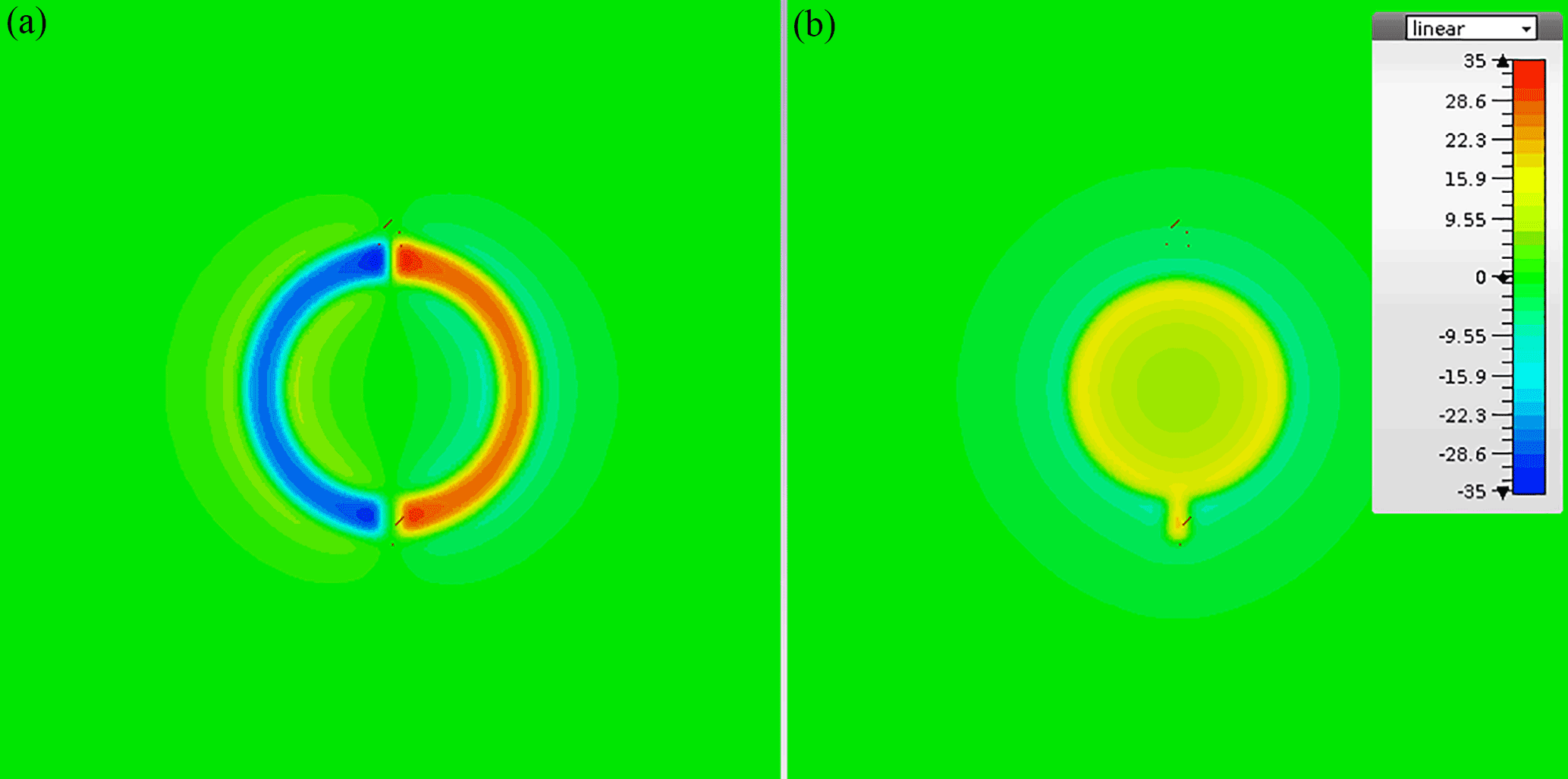
Figure 5Magnetic field distribution for common mode (a) and differential mode (b) excitation.
The simulation model shown in Fig. 4 has been used to optimise the coil structure. The outer radius has been kept constant at 17 mm while the inner radius was swept to achieve equal self inductance at both ports. This was achieved for an inner radius of 12.6 mm. As a first simulation result, the magnetic field distribution was calculated for the case of just stimulating one of the two ports at a time. When fed with a common mode signal at port 1, the structure generates a quadrupol magnetic field which is symmetric to the cutting plane s. Feeding port 2 in differential mode leads to a dipole magnetic field inside the inner part of the structure. Figure 5 shows the magnetic field distribution plots for both cases on a parallel plane with a distance of 1.5 mm to the structure.
To demonstrate the decoupling effect, two of these structures were coupled in a subsequent simulation at a distance of 3 mm, comparable to the intended usage for inductively coupled full-duplex data transfer.
As results, mixed mode S-paramters were obtained in the simulation and finally compared to measurement results of the fabricated PCB coils (Fig. 4), which were conducted with a fully differential network analyzer. In simulation and measurement, the ports 1 and 3 were connected to the differential mode (inner) part of the structures, ports 2 and 4 to the common mode (outer) parts.
The results are presented in the form of differential S-parameters. The naming of the parameters indicate the modes of stimulus and signal detection, d stands for differential and c for common mode. Sdd denotes a differential stimulation of the structure at one port and differential signal pickup at the corresponding second port. Scc is susequently the same for common mode stimulation and signal detection. The mixed mode parameter Sdc indicates the structure's mode-conversion as the stimulus is a common mode signal whereas a common mode signal is detected.It thus respresents the decoupling of both channels in case of the dualcoil. The second mixed mode parameter, Scd, is equal to the latter and therefore not explicitly plotted.
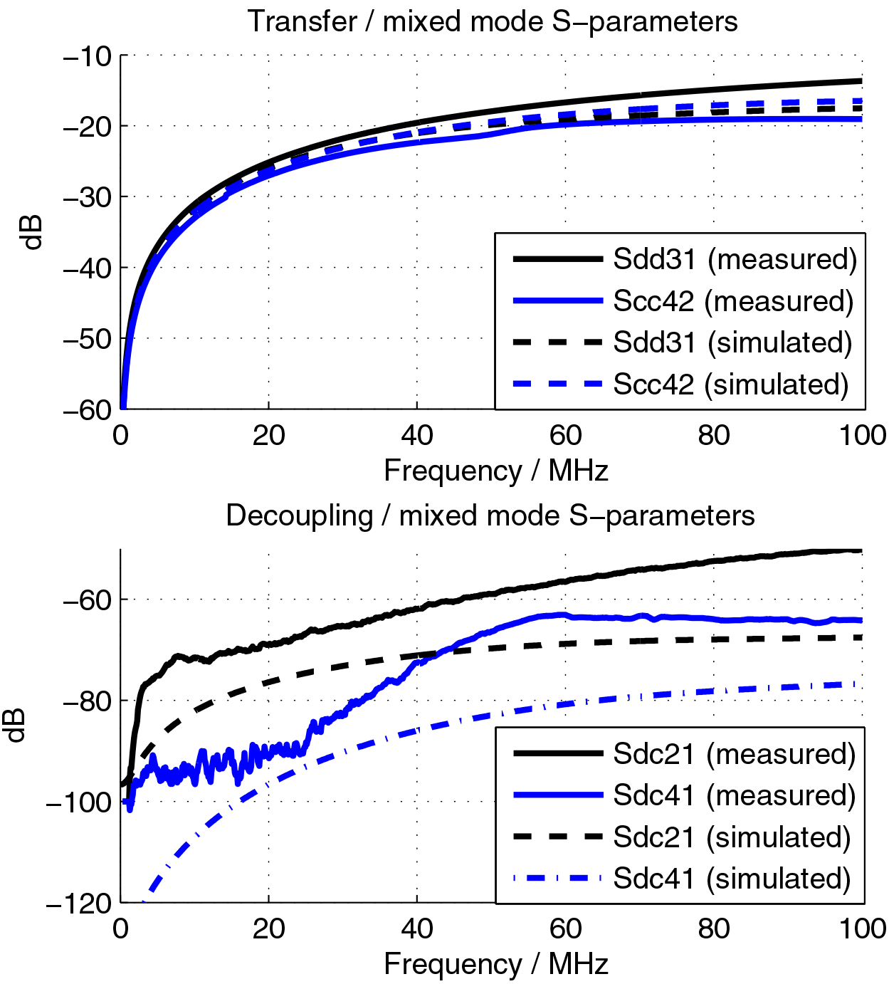
As can be seen from Fig. 6, simulation and measurement are in good agreement with theory, leading to comparable transfer channels. Near-end (Sdc21) and far-end (Sdc41) crosstalk are in the range of −60 dB at 50 MHz while the signal transfer function is at approximately −20 dB. The difference between simulation and measurements, especially for the decoupling is mainly due to fabrication tolerances and measurement uncertainties.
To further show that the dualport coil structure improves the decoupling between two transfer channels significantly for the very limited space given, a second simulation has been performed. As can be seen from Fig. 7, two concentric circular loops have been implemented, the radii beeing equal to those of the optimised dualport structure.
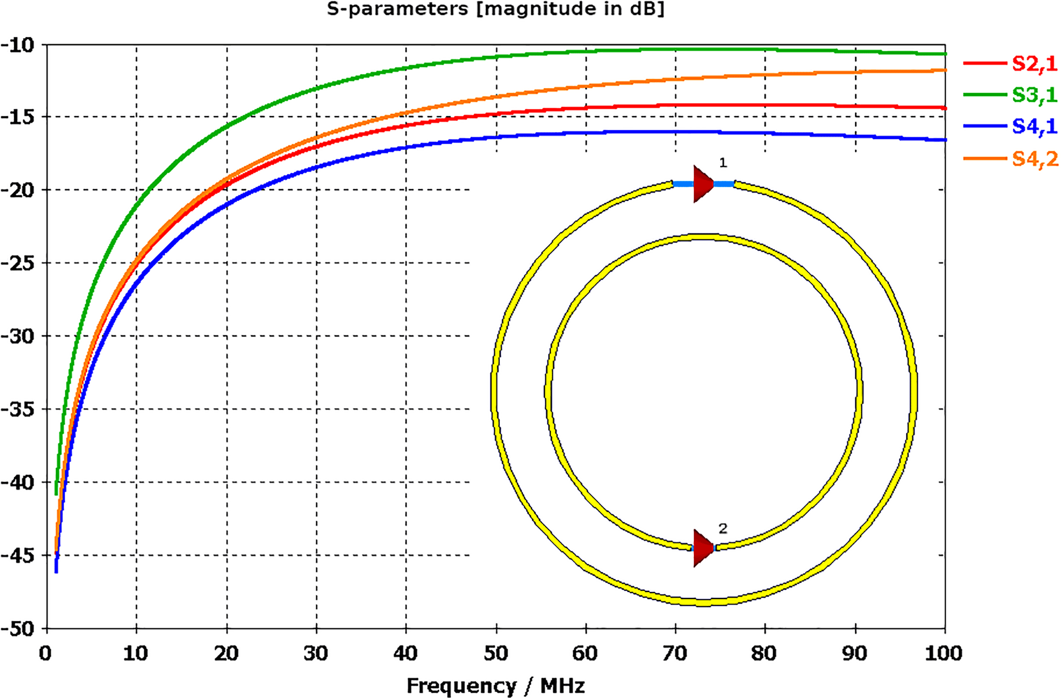
In the simulation, two of these structures were coupled at a distance of 3 mm, just like for the dualport coil before. The ports 1 and 3 were connected to the outer loops of each structure, ports 2 and 4 to the inner. The decoupling (S21 for NEXT respectively S41 for FEXT) for this structure is in the range of −15 dB at 50 MHz while the main signal transfer is just slightly higher. In conclusion, by using the dualport coil structure, a gain in decoupling of more than 40 dB has been achieved using the same space.
A compact dualport coil using multipole magnetic field distribution has been presented. The structure allows for full-duplex data transfer with high crosstalk suppression and comparably small space requirements, thus simplifying system design. Simulation and measurement of an optimised structure have been conducted and both are in good agreement with the theory presented. A comparison to conventional single loop coils has been presented, showing a significant improvement in decoupling for the dualport structure of more than 40 dB.
Using this structure, full-duplex inductively coupled data transfer can be implemented in a very limited space with applications ranging from implants, general near field communication applications or even wireless power and data tranfer systems.
The underlying simulation and measurement data as well as the simulation model can be requested by the corresponding author.
The authors declare that they have no conflict of interest.
This article is part of the special issue “Kleinheubacher Berichte 2017”. It is a result of the Kleinheubacher Tagung 2017, Miltenberg, Germany, 25–27 September 2017.
This work was supported by the german Federal Ministry for Economic Affairs
end Energy through the program “Zentrales Innovationsprogramm Mittelstand”
(ZIM), grant number ZF4050305PR6.
Edited by:
Romanus Dyczij-Edlinger
Reviewed by: two anonymous referees
Biehler, T., Prottet, M., Nguyen, V., and Perriard, Y.: Contactless Power and Information Transmission, IEEE T. Ind. Appl., 38, 1266–1272, 2002. a
Han-Joon Kim, J.-W. C.: Crosstalk-free Magnetic MIMO Communication Using Heterogeneous Antenna Array, URSI Asia-Pacific Radio Science Conference, 2016. a
Jackson, J. D.: Klassische Elektrodynamik, vol. 3, DE GRUYTER, 2002. a
Douarville-Blaise, J.-P., Pouhè, D., and Hirai, J.: Eliminate Crosstalk Using Symmetry in MIMO Arrays of Inductive Antennas: An Introduction to Pie-Chart Antennas, Prog. Electromagn. Res., 75, 149–173, 2017. a
Kim, H.-J., Park, J., Oh, K.-S., Choi, J. P., Jang, J. E., and Choi, J.-W.: Near-Field Magnetic Induction MIMO Communication Using Heterogeneous Multipole Loop Antenna Array for Higher Data Rate Transmission, IEEE T. Antenn. Propag., 64, 1952–1962, 2016. a
Maxwell, J. C.: A Treatise on Electricity and Magnetism, vol. 2 of Clarendon Press, Macmillian and Co., 1873. a, b
Poon, A., Chang, A., Samavati, H., and Wong, S.: Reduction of Inductive Crosstalk Using Quadrupole Inductors, IEEE J. Solid-St. Circ., 44, 1756–1764, 2009. a
Rathge, C. and Kürschner, D.: High efficient inductive energy and data transmission system with special coil geometry, IEEE 13th European Conference on Power Electronics and Applications, 2009. a