 | 19 Sep 2019
Dielectric corner reflectors for mmWave applications
Christian Buchberger
Florian Pfeiffer
Erwin Biebl
Using dielectrics instead of conventional metallic structures, this article investigates the properties of the proposed dielectric corner reflectors for use in a number of millimeter wave (mmWave) applications. Material characterizations of different typical plastics using transmission measurements are presented, as well as an analysis of their respective radar cross section (RCS) when used as corner reflectors. They exhibit similar behavior as conventional metallic ones, while intrinsic dielectric losses reduce the overall RCS. Additionally, two use cases are presented. One shows the potential capabilities by combining a dielectric with a metallic corner reflector to increase its opening angle. The other gives rise to the possibility of using several single dielectric reflectors in array configurations to further increase the overall RCS, while introducing grating lobes.
- Article
(4162 KB) - Full-text XML
- BibTeX
- EndNote


The need for defined targets for a manifold of radar applications is rising, especially as mmWave radars enter the automotive regime. Metallic corner reflectors are commonly used as such targets. They exhibit a known and, relative to their size, high radar cross section over a large opening angle. This is because of their retroreflective abilities, i.e. waves that enter the opening of the corner reflector are reflected back to the source of origin (Knott, 1993).
In naval and airborne applications, radar reflectors are used for positioning and localization. In remote sensing applications, corner reflectors have seen a lot of attention, especially by synthetic aperture radar research, where requirements led to special investigations, including geometrical behavior (Ferrara et al., 1995) and depolarizing properties (Sheen et al., 1992). In automotive applications however, they are most commonly used for radar system evaluation and as calibration targets (Visentin et al., 2017; Schmid et al., 2013; Sarabandi and Chiu, 1996).
The use of such reflectors in urban road traffic scenarios, especially regarding road safety, such as the marking of infrastructural objects, road works or even road users, would result in a need for a high number of such corner reflectors. Notably small radar targets like pedestrians (Yamada et al., 2005) or cyclists would benefit from structures to enhance their radar cross section (Hallbjörner and Cheng, 2013; Liao et al., 2018). Therefore, a cost-efficient solution provided by the use of full body dielectric structures would be beneficial, as they are easy and inexpensive to fabricate.
Similar dielectric devices are known from optics. These so called trihedral prisms or corner cube retroreflectors are based on the principle of total internal reflection. Rays that enter the corner cube retroreflectors are reflected at material borders (e.g. crown glass and air) and return to the source for angles larger than the material dependent critical angle (Eckhardt, 1971). However, in optics neither the reflected power, in the sense of RCS, nor the maximum opening angle is of interest, but rather the minuscule beam deviation between the incident and reflected beam. As the phenomenon of total internal reflection also holds true for millimeter-waves, this article proposes dielectric trihedral corner reflectors, designed especially for mmWave radar applications.
Starting from the conventional triangular trihedral corner reflector and its properties in Sect. 2, the dielectric corner reflector is motivated and its inner working principle is described. Section 3 gives insight into material characteristics and the evaluation of different materials from which prototypes are built. The RCS measurement setup is then described in Sect. 4 and reference results are presented. Continuing in Sect. 4.2 measurement results of the different dielectric reflector prototypes are shown and evaluated. After a short digression and discussion about using a combination of dielectric and conventional reflectors, the possibilities of reflector array structures are presented in Sect. 4.4 as well as analytical calculations and measurement results. Finally the conclusion ends the article and proposes further future investigations.
One of the most common radar reflectors is the triangular trihedral corner reflector. Its geometry is shown in Fig. 1. It is comprised of three metallic isosceles triangular faces whose catheti stand perpendicular to each other. An incident wave denoted by the wavevector k that impinges the opening ABC, is reflected back into the same direction due to the retroreflective abilities of the reflector. The angles of incidence ϕi and θi are counted from the normal of the open face n. In the following, the monostatic radar cross section is only shown and measured in the azimuthal plane θi=0∘, i.e. at θ=54.7∘.

Figure 1Geometry of the trihedral corner reflector. The vertices A, B, C are located equidistantly from the origin O. The angles ϕi,θi denote the incident wave k counted from the axis of symmetry at ϕ=45∘ and the normal of the open face at θ=54.7∘ represented by n.
For a triangular trihedral corner reflector, the monostatic RCS at bore sight is given in Knott (1993) and can be calculated with
where λ is the wavelength of the electromagnetic wave and the length of one cathetus. From Eq. (1) it is apparent, that the RCS of such a trihedral corner reflector increases proportionally with the square of its effective opening area. This effective area is highly angle dependent and decreases drastically over larger incidence angles in azimuth as well as elevation. A detailed geometrical derivation and the analytical angle dependency of this particular radar reflector can be found in Doerry (2008).
Dielectric corner reflectors
In the case of full body dielectrics without metallization, the key principle to achieve reflective surfaces for retroreflectivity is the phenomenon of total internal reflection at the boundary between an optically thick and thin medium. The characterizing parameter is the index of refraction proportional to the relative permittivity of the medium. In this case, the optically thick medium is the dielectric of choice (n2), whereas air functions as the optically thin medium (n1), so that n2>n1. The ratio of the refractive indices of the two media determine the critical angle
under which all power is reflected at the boundary if exceeded, derived over the well known Snell's law (Hecht, 2009)
The dielectric trihedral corner reflector is a full body tetrahedron that forms when the surface ABC is closed and filled to the origin O with a dielectric. For simplicity's sake, a cut at θ=90∘ through this body, i.e. a solely dihedral problem, is shown in Fig. 2. Here, the ray optical trajectory for a impinging wave with incidence angle ϕi shows a refraction at the first boundary, followed by a total internal reflection at the second one. As the reflecting surfaces are perpendicular to another, the returning ray leaves the body under the same angle ϕi back to the source. This holds true only for incidence angles with sufficient steepness. For increasingly flatter incidence angles that consequently will be smaller than the critical angle ϕc, parts of the power of the wave will leak from the dielectric, resulting in a lower RCS. The amount of leakage is also angle dependent and follows the Fresnel equations (Hecht, 2009).
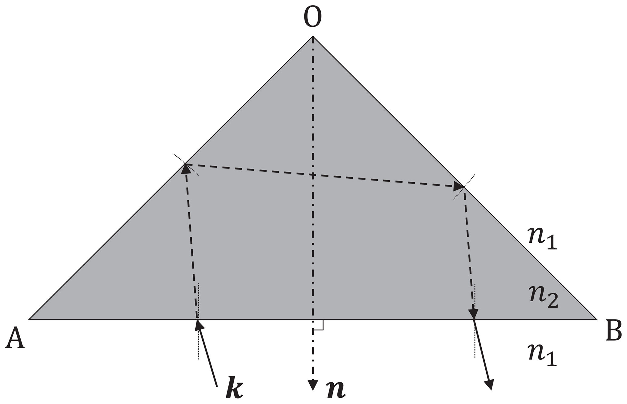
Figure 2Top view profile of the full body dielectric corner reflector at θ=90∘. Incident waves are refracted into the body and totally reflected for angles larger than the critical angle at the boundary of the optically thick to thin medium.
Four different full body dielectric corner reflectors were manufactured, all having the same edge length of a=4.1 cm corresponding to a maximum RCS for an equivalent metallic reflector at bore sight of dBm2 = 0.8 m2. The reflectors differ in the material that was used as well as the manufacturing process and are shown in Fig. 3. One is made of acrylonitrile butadiene styrene (ABS) using fused deposition modelling (FDM), one made of an epoxy compound by stereolithography (SLA), one made of polyamide-12 (PA12) by selective laser sintering (SLS) and one is milled from polystyrene (PS). The layer thickness of the 3-D printed models is well below the wavelength inside the dielectric of about 2.4 mm, so that no effects through intrinsic interferences are expected. The materials that were used are all common plastics and, especially in the case of the thermoplastics (ABS, PA12, PS), they present themselves as viable candidates for a cost efficient mass production when manufactured via injection molding. The material characterization was done using a transmission measurement setup by Pfeiffer et al. (2008) in the E-band at 76.5 GHz. The results in Table 1 show that the relative permittivity ϵr is very similar throughout all materials and will not alter the behavior of the reflectors significantly as the critical angle differs only by half a degree. Concerning the loss tangent tan δ however, one can see substantial differences. While PS shows the smallest losses that are even below the measurement accuracy of the measurement setup, ABS and PA12 have little more losses in the same order of magnitude. The epoxy compound exhibits the highest losses, that can be explained by its composition. Due to the accessory agents propylene carbonate and trisulfonium salts (3DSystems, 2016), the properties of pure epoxy are degraded.
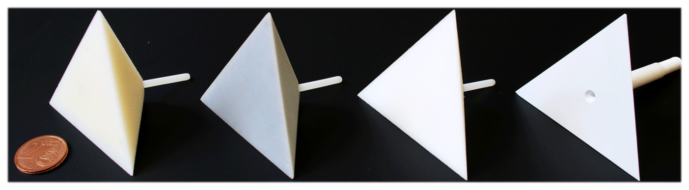
Figure 3Different manufactured dielectric corner reflector models. From left to right: ABS, Epoxy Compound, PA12, Polystyrene.
Table 1Relative permittivity and loss tangent of different dielectrics obtained by transmission measurements at 76.5 GHz and process dependent layer thicknesses.
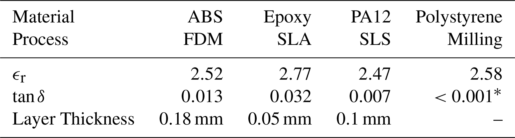
* Value below measurement accuracy.
All RCS measurements were done using a frequency modulated continuous wave (FMCW) radar module by Texas Instruments, the AWR1642BOOST (TexasInstruments, 2017). Of all transmit and receive channels, only one of each was used. The measurement was set up so that the linearly polarized antennas were vertically aligned to the device under test (DUT). Using FMCW to measure the RCS has the advantage of directly finding the DUT in the received range spectrum in the range bin that corresponds to the radial distance to the DUT. If the range resolution is sufficiently small to distinguish between (interfering) sources as well as sufficiently broad, so that the target will not appear in several different range bins, the measured peak of the relative power will correspond to the DUTs RCS. With a bandwidth of B=1 GHz, the range resolution results to 15 cm. The DUT was mounted on a rotary table NR360S by Thorlabs in a distance of 3.6 m. In the following, measurements were done in steps of 1∘. As the RCS is not measured at a single reference frequency but more so over of the whole FMCW bandwidth, the RCS must be evaluated at every frequency point and subsequently be averaged. For a perfectly linear ramp, the measured RCS is
and the result is equivalently the RCS at the center frequency of the FMCW ramp, here at 76.5 GHz (Ruck et al., 1970).
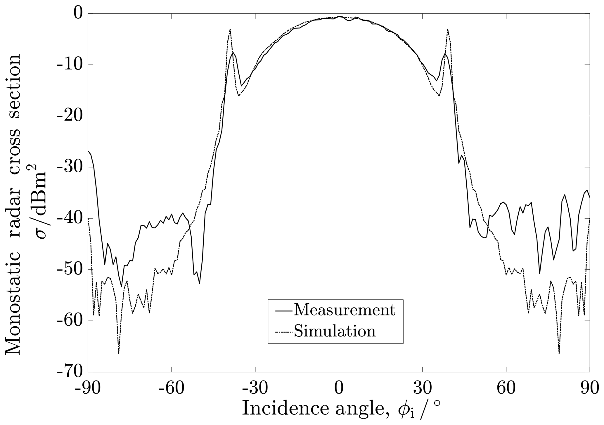
Figure 4Measured and simulated (PEC) monostatic RCS of conventional metallic trihedral corner reflectors with identical edge length at θi=0∘. CST MWS Simulation: Integral Equation Solver.
Measurements without a DUT yielded a noise floor level of Pnoise=50 dB given in a relative power scale by the sensor system, whereas the maximum received power was found for the metal corner reflector with edge length a=4.3 cm as Pmax=96.75 dB at bore sight, resulting in a dynamic range of 46.75 dB, suitable for RCS measurements. To obtain the value of the measured RCS in square meters, the measured relative power values were normalized to the maximum received power that corresponds to exactly the metal corner reflector at bore sight with dBm2 = 0.9 m2 at 76.5 GHz, calculated using Eq. (1).
Figure 4 shows the measured monostatic RCS of the metal corner reflector in the azimuthal plane in comparison with a simulated one made of a perfect electric conductor (PEC) using CST Microwave Studio. The measurement is in very good correspondence with the simulation, especially in the range of ϕi ∈ [−45∘; 45∘]. The characteristic narrow sidelobes can be seen at approximately ∘. The half power beam width of such a reflector, i.e. the opening angle in which the reflected power has decreased to half of its maximum, is ϕ3 dB=38∘ much alike the indication by Ruck et al. (1970). In the following, the metal corner reflector will be used as a reference for the dielectric reflectors.
4.1 RCS measurement results
The measurement results of the different dielectric corner reflectors in comparison with the conventional metallic one can be seen in Fig. 5. Although the overall shape of the angular dependency of all reflectors seem similar, three major differences become apparent. Firstly, the characteristic side lobes of the metallic reflector vanish. This is because of the waves leaking from the dielectric at that exact incidence angle, as total internal reflection is no longer ensured.
Secondly, the RCS of the dielectric reflectors is inferior to that of the metallic corner reflector over all incidence angles. This is due to the intrinsic losses inside the dielectric. This attenuation leads to a mean difference between the PS and the reference reflector of approximately 7 dB inside the HPBW of the metal reflector. The models made of PA12 and ABS show even lower RCS as the one made from PS, that is attributable to their higher loss tangent. Even further attenuated is the one made of the epoxy compound.
Finally, all dielectric corner reflectors exhibit a significant peak at ϕi=0∘. Due to the partial power reflection at the border from air to the medium, the part of this surface reflection will not be attenuated inside the dielectric. The reflected power for incidence parallel to the surface normal is approximately 5 % for a vertically polarized wave given by Fresnel's equations. Additionally to the first reflection, an interference with the residual of the wave coming from inside the dielectric occurs. In the case of the epoxy compound, one can see that effect, as the peak at bore sight is much higher than over the remaining incidence angles.
All three thermoplastics, ABS, PA12 and PS, prove themselves to be viable materials for dielectric corner reflectors. Although the mean RCS is lower than that of a metallic one, they are still bright targets and in regard to ease manufacturing, production costs and application requirements potentially preferable.
Figure 5Comparison of the measured monostatic RCS of different dielectric corner reflectors and a conventional metallic one.
4.2 Dielectrically filled corner reflectors
Depending on the application, a wide angular coverage that exceeds the approximately 38∘ of an ordinary corner reflector may be required. Using dielectrics in combination with metallic structures can lead to such results.
Figure 6Measurement results of the combined dielectric/metallic corner reflector in comparison to the individual reflectors and simulation results (CST MWS, lossless dielectric ϵr=2.6).
A combined metallic and dielectric retroreflective element that is known is the Luneburg lens reflector. Due to its negative gradient of the refractive index from the center of the sphere outwards, all incoming rays independent of their direction are reflected at a metallization on the surface and refracted back into the direction of their origin. Although it shows a higher HPBW and RCS than the trihedral corner reflector, the Luneburg lens is not very widespread as a radar reflector, as the gradient is relatively complex to manufacture (Ruck et al., 1970).
Profiting from previous insights about dielectric corner reflectors, a combinatory approach to achieve a flatter RCS over the angle of incidence, i.e. a higher HPBW is now investigated. If a metallic corner reflector is filled with a dielectric, or equivalently, the three rear sides of a dielectric corner reflector are metalized, Snell's law suggest that impinging rays are refracted into the reflectors dielectric nonlinearly. Thus, the overall RCS over the angle of incidence will flatten and the HPBW will increase.
For the measurements, the prototype made of PS was inserted into the triangular trihedral corner reflector. In Fig. 6, the measurement in comparison with the individual elements and simulation results is depicted. In the case of the simulation with a lossless dielectric, two substantial differences to the conventional reflector are recognizable. Firstly, the characteristic sidelobes disappear like in the case of an individual dielectric reflector. Secondly, the HPBW greatly improves by 42 % to a value of ϕ3 dB=54∘. The measurement shows similar angular behavior, although a non inconsiderable amount of ripple occurs. This can be traced back to interferences between the dielectric and the metal, as their alignment is not perfect and a small gap of air was present. The maximum RCS is similar to the single PS reflector and confirms the results from Sect. 4.1, that there is no particular leakage from the dielectric for small incident angles and that the losses occur inside the dielectric.
4.3 Dielectric corner reflector arrays
As discussed in Sect. 2, in order to increase the RCS of a single element, the reflector not only has to grow in width but also in depth. If it is desired to increase the RCS in cases where the mounting depth is restricted, one can overcome this issue by building array structures consisting of single reflective elements. The idea is similar to optical cat eye reflectors, where the single elements of the array are much bigger than the wavelength and the far-field interference pattern is not of interest. Here however, as the distances between the single elements are only some multiples of the wavelength, the far field RCS of such arrays can be calculated by the array factor (AF).
Figure 7Dielectric corner reflector array consisting of four milled polystyrene tetrahedrons. Their corresponding phase centers are marked with a red dot.
The AF of a planar array is given in Balanis (2005). A generalized AF for non-uniformly distributed N isotropic radiators without progressive phaseshifts can be given by
where αm is the complex weight of each single element the wavenumber and
the position of the m-th element. For identical passive reflecting elements the weights αm are unity. The resulting RCS of the array is the product of the AF and the RCS of a single element, acting as an envelope:
As an example, a dielectric corner reflector array was built, comprised of four identical reflectors made of polystyrene as presented in Sect. 3. As shown in Fig. 7, they were arranged in a star like fashion, with their phase centers on a plane (i.e. v=0) and relative cartesian coordinates
As the effective area is fourfold (N=4), the maximum observable RCS is expected to be 12 dB higher in comparison to the single reflector. Measurements of the array on the azimuthal plane in comparison with a single polystyrene reflector are shown in Fig. 8. Due to the high angular dependency of the RCS, the measurement was done in steps of 0.25∘. It is apparent that the RCS is highly angle dependent and follows the overall shape of the single element, as described by Eq. (6). The geometry of the array exhibits a high number of grating lobes, as the elements are placed in distances larger than λ∕2, causing spatial aliasing. The maximum of the array is measured to be 11.4 dB higher as the single element, very close to the expected 12 dB. Between incidence angles of −35 to 35∘, the mean difference between the single element and the array is 5 dB.
Figure 8Monostatic RCS of the dielectric corner reflector array in comparison to the single element. The dashed line corresponds to the product of the calculated AF times the RCS of the measured single element, i.e. the envelope.
This shows the capabilities of an array of dielectric corner reflectors, that is higher in maximum RCS while keeping its depth constant. Although dips in the RCS are present that are lower than the RCS of a single reflector, in practice those should not be of concern when dealing with moving scenarios where the sensor passes by objects of interest. On the contrary, if the capabilities of the measuring system, i.e. the radar, satisfy spatial sampling in a way such that these grating lobes could infer encoded information, these arrays could also be used to label objects.
This article shows, that using the same theory known from conventional metallic corner reflectors and the principle of total internal reflection, dielectric tetrahedrons can be built to act as retroreflective elements. The overall lower radar cross section over the half power beam width of around 7 dB results from the dielectric losses and are material dependent. Pure thermoplastics such as ABS, PA12 and polystyrene are potential candidates for a cost-efficient production. Furthermore, when metalized, such reflectors would exhibit a much wider angular coverage in comparison to their solely metallic counterparts. When used in array configurations, the overall radar cross section follows the array factor of the geometry, introducing grating lobes but also increasing the radar cross section while maintaining the same mounting depth as a single reflector element. With help of the array factor, one can potentially find array geometries that fit the applications' requirements or even add spatially encoded information in a bar code like fashion.
Data used in this paper is available upon request: Christian Buchberger (chris.buchberger@tum.de).
CB developed all concepts based on the initial idea of EB, did simulations, RCS measurements and the evaluation of all results. FP did all permittivity measurements and helped with the RCS measurements. CB prepared the manuscript with feedback from FP and EB.
The authors declare that they have no conflict of interest.
This article is part of the special issue “Kleinheubacher Berichte 2018”. It is a result of the Kleinheubacher Tagung 2018, Miltenberg, Germany, 24–26 September 2018.
This work was supported by the German Research Foundation (DFG) and the Technical University of Munich (TUM) in the framework of the Open Access Publishing Program.
This paper was edited by Madhu Chandra and reviewed by Madhu Chandra and one anonymous referee.
3DSystems: Safety Data Sheet: Accura® Xtreme™, available at: http://infocenter.3dsystems.com/materials/sla/accura-xtreme, last access: 11 January 2016. a
Balanis, C. A.: Antenna Theory, John Wiley & Sons, Hoboken, New Jersey, USA, 2005. a
Doerry, A. W.: Reflectors for SAR Performance Testing, Sandia Report SAND2008-0396, Unlimited Release, Sandia National Laboratories, Albuquerque, New Mexico, USA, 2008. a
Eckhardt, H.: Simple Model of Corner Reflector Phenomena, Appl. Optics, 10, 1559–1566, 1971. a
Ferrara, G., Mattia, F., and Posa, F.: Backscattering Study on Non-Orthogonal Trihedral Corner Reflectors, IEE Proceedings on Microwaves, Antennas and Propagation, 142, 441–446, 1995. a
Hallbjörner, P. and Cheng, S.: Improvement in 77-GHz Radar Cross Section of Road Work Jacket and Side Screen by Use of Planar Flexible Retrodirective Reflectors, IEEE Antenn. and Wirel. Pr., 12, 1085–1088, 2013. a
Hecht, E.: Optik, Oldenburg Wissenschaftsverlag, 5th Edn., 2009. a, b
Knott, E. F.: Radar Cross Section Measurements, Springer Science & Business Media, New York, USA, 1993. a, b
Liao, W.-J., Hou, Y.-C., Tsai, C.-C., Hsieh, T.-H., and Hsieh, H.-J.: Radar Cross Section Enhancing Structures for Automotive Radars, IEEE Antenn. Wirel. Propag., 17, 418–421, 2018. a
Pfeiffer, F., Biebl, E., and Siedersberger, K.-H.: Determination of Complex Permittivity of LRR Radome Materials Using a Scalar Quasi-Optical Measurement System, in: Advanced Microsystems for Automotive Applications 2008, 205–210, Springer, Berlin, Germany, 2008. a
Ruck, G. T., Barrick, D. E., Stuart, W. D., and Krichbaum, C. K.: Radar Cross Section Handbook, Volumes 1 & 2, Plenum Press, New York, 1970. a, b, c
Sarabandi, K. and Chiu, T.-C.: Optimum Corner Reflectors for Calibration of Imaging Radars, IEEE T. Antenn. Propag., 44, 1348–1361, 1996. a
Schmid, C. M., Pfeffer, C., Feger, R., and Stelzer, A.: An FMCW MIMO Radar Calibration and Mutual Coupling Compensation Approach, in: European Radar Conference (EuRAD), Nürnberg, Germany 13–16, IEEE, Piscataway, New Jersey, USA, 2013. a
Sheen, D. R., Johansen, E. L., Elenbogen, L. P., and Kasischke, E. S.: The Gridded Trihedral: A new Polarimetric SAR Calibration Reflector, IEEE T. Geosci. Remote Sens., 30, 1149–1153, 1992. a
TexasInstruments: AWR1642 Evaluation Module (AWR1642BOOST) Single-Chip mmWave Sensing Solution, SWRU508B, available at: http://www.ti.com/lit/ug/swru508b/swru508b.pdf, last access: 11 January 2017. a
Visentin, T., Hasch, J., and Zwick, T.: Calibration of a Fully Polarimetric 8×8 MIMO FMCW Radar System at 77 GHz, in: 11th European Conference on Antennas and Propagation (EUCAP), Paris, France, 2530–2534, IEEE, Piscataway, New Jersey, USA, 2017. a
Yamada, N., Tanaka, Y., and Nishikawa, K.: Radar Cross Section for Pedestrian in 76GHz band, in: European Microwave Conference, Paris, France, Vol. 2, 4–7, IEEE, Piscataway, New Jersey, USA, 2005. a