 | 19 Sep 2019
Results of the national antenna intercomparison 2017/2018 within the German Calibration Service (Deutscher Kalibrierdienst – DKD)
David Ulm
Thomas Kleine-Ostmann
Thorsten Schrader
In an intercomparison organized within the framework of the German Calibration Service (Deutscher Kalibrierdienst – DKD), seven different calibration laboratories participated in the measurement of the antenna factor for three different antennas according to different standards. Between August 2017 and April 2018, measurements have been performed on a hybrid antenna, a logarithmic-periodic antenna and on an Open Ended Waveguide.
- Article
(2401 KB) - Full-text XML
- BibTeX
- EndNote


The German Calibration Service (Deutscher Kalibrierdienst – DKD), is the association of the accredited laboratories in Germany (PTB-Mitteilungen, 2015) hosted at the Physikalisch-Technische Bundesanstalt (PTB), the German National Metrology Institute (PTB-Mitteilungen, 2015). The accredited laboratories in Germany are required to prove that they can determine the antenna factor correctly and traceable to the International System of Units (SI) including the specification of measurement uncertainties (GUM, 2008). Between August 2017 and April 2018, intercomparison measurements have been performed on a hybrid antenna (Schwarzbeck VULB 9163, 30 MHz–3 GHz), a logarithmic-periodic antenna (Schwarzbeck USLP 9142, 650 MHz–8 GHz) and on an Open Ended Waveguide (OEWG) in LA band (R22 or W430, 1.7 GHz–2.6 GHz) with the goal to determine the free-space antenna factor in 10 MHz steps. Below 1 GHz, measurements of the USLP and VULP antennas have been performed using the Standard-Site-method according to CISPR 16-1-6 (CISPR 16-1-6, 2014) with 10 m measurement distance on an open-area test site (OATS) or in a semi-anechoic chamber (SAC). Above 1 GHz, calibrations on USLP and VULB antennas have been performed at 3 m measurement distance in vertical or diagonal polarization according to IEEE 149 (ANSI/IEEE 149-1979, 2002), CISPR 16-1-6 (CISPR 16-1-6, 2014), ANSI C63.5 (ANSI C63.5, 2017) or to an in-house method. Additionally, single laboratories have measured VULP, USLP and OEWG antennas in 1 m distance with antenna tip as reference point according to SAE ARP 958D (SAE ARP958D, 2003).
The results, which have been documented in the DKD report DKD-V 2.5 (DKD-V 2.5, 2018), show good agreement within the specified measurement uncertainties, which seem to be realistic. While some laboratories consider variation of the phase center position for antenna factor calculation, other laboratories foresee an additional contribution to measurement uncertainty, only. However, the systematic errors introduced by this have only a minor effect on the validity of the intercomparison.
During the 42nd meeting of the DKD technical committee “High Frequency and Optics” on 16 May 2018 in Braunschweig, it was decided to initiate an antenna factor intercomparison for all interested laboratories between August 2017 and April 2018 organized by PTB.

Figure 1Free-space antenna factor of the Schwarzbeck VULB 9163 measured at PTB at the beginning and at the end of the intercomparison.
2.1 Participants
In addition to PTB, six accredited and non-accredited laboratories participated in the intercomparison: AMETEK CTS Europe GmbH in Berlin, Bureau Veritas Consumer Products Services Germany GmbH in Nürnberg, EMCCons DR. RAŠEK GmbH & Co. KG in Unterleinleiter, Obering. Berg & Lukowiak GmbH in Hüllhorst, Schwarzbeck Mess-Elektronik OHG in Schönau and Rohde & Schwarz Messgerätebau GmbH in Memmingen. To guarantee anonymity, the ordering of laboratories does not correspond to the numbering of laboratories in the results section.
2.2 Measurands
The frequency and direction dependent free-space antenna factor is defined as ratio of electric field strength and feeding-point voltage UR at a reference impedance of R=50Ω:
For measurement of the free-space antenna factor, different measurement methods have been established depending on frequency range and measurement site. Usual methods are the Standard Site Method (SSM), the Standard Antenna Method (SAM) and the Three Antenna Method. As all methods claim traceability for the free-space antenna factor, results from different methods should be consistent which will be tested in this intercomparison.
The 1 m antenna factor according to SAE ARP 958D (SAE ARP958D, 2003) is based on Eq. (1) as well but uses the transmission measurement between two equal antennas (two antenna method) with 1 m distance between the tips and the Friis formula (Gustrau, 2013) without further correction. Therefore, the determined antenna factor is not comparable with the free-space antenna factor determined with the other methods denoted here.
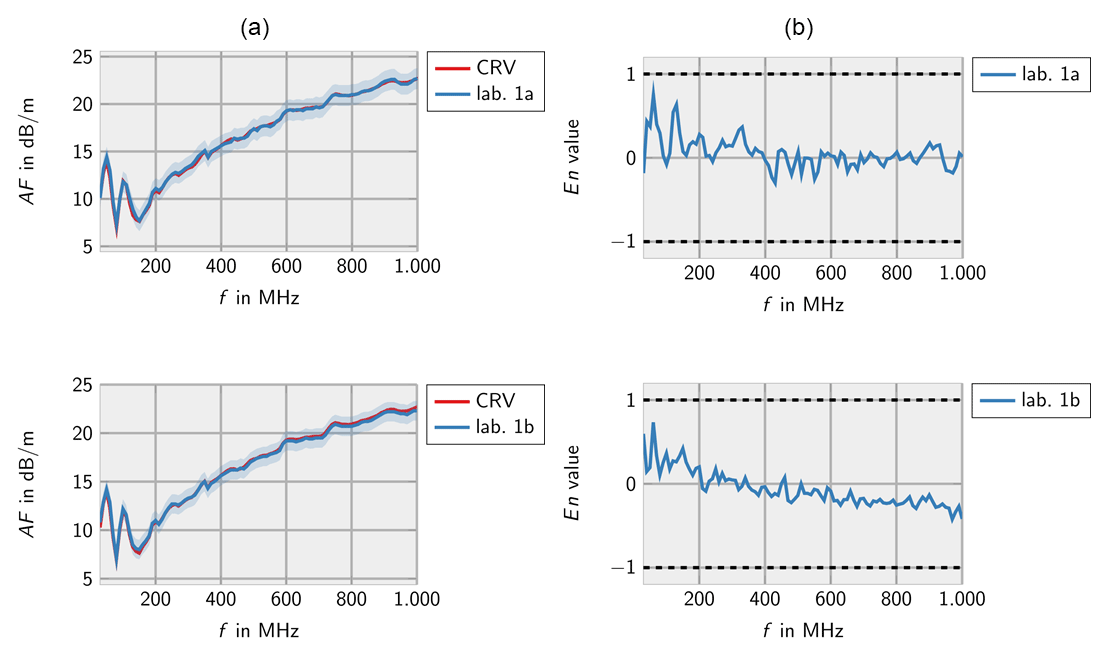
Figure 2Measurements of lab 1 for the Schwarzbeck VULB 9163 (a) and corresponding En values (b). Measurement 1a according to ANSI C63.5 (10 m). Measurement 1b according to CISPR 16-1-6 (10 m).
2.3 Travelling standards
For the intercomparison, three different antennas have been used as travelling standards. For the frequency range 30 MHz–3 GHz, a hybrid antenna (Schwarzbeck VULB 9163, see VULB, 2018) with N(f) connector has been provided by the manufacturer. For the frequency range 650 MHz–8 GHz, a logarithmic-periodic antenna (Schwarzbeck USLP 9142, see USLP, 2018) with N(f) connector has been provided by PTB. In addition, an Open Ended Waveguide (OEWG) in LA band (R22 or W430) with N(f) coaxial-to-waveguide transition from M. W. Microwave Corporation has been used in the frequency range 1.7GHz –2.6 GHz provided by PTB.
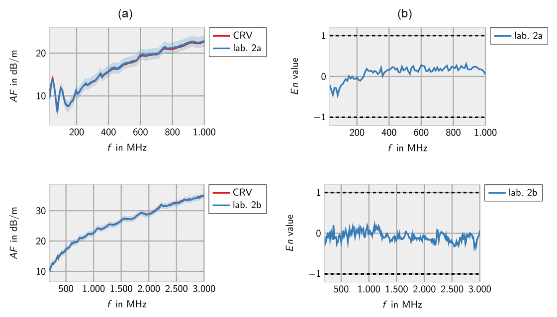
Figure 3Measurements of lab 2 for the Schwarzbeck VULB 9163 (a) and corresponding En values (b). Measurement 2a according to Standard-Site-Method (CISPR 16-1-6, ANSI C63.5). Measurement 2b according to Three-Antenna-Method (CISPR 16-1-6, ANSI C63.5).
2.4 Data evaluation
Consistency of the measurement results has been evaluated with the En criterion (Krystek, 2012; Cox, 2000). Here, the difference between a measurement value xi and a reference value CRV (Comparison Reference Value) will be calculated.
This difference is denoted as Degree of Equivalence (DoEi). The reference value CRV is determined as weighted mean of all N measurements of the different laboratories in such a way that the laboratories contribute according to their measurement capabilities. Results with lower specified standard measurement uncertainty u(xi) contribute stronger as represented by a higher weighting factor wi:
Provided that the measurement results are statistically independent, according to the “Guide to the expression of uncertainty in measurement” (GUM, 2008), it follows for the uncertainty u(CRV) of the Comparison Reference Value:
Normalizing the DoEi to the corresponding expanded measurement uncertainty U(DoEi) (which in case of a sufficiently high effective degree of freedom corresponds to twice the standard measurement uncertainty for a confidence interval of 95 %) results in the Eni value, which is a measure for the conformity of the individual measurement with the Comparison Reference Value:
As long as the participating laboratories estimate their measurement uncertainties realistically, the Eni absolute value is below one in 95 % of all cases. Considering the strong covariance between measurement value xi and reference value CRV (as the measurement value was used to calculate the reference value), the following equation can be used to calculate the Eni value:
Note that due to the correlation of single measurement value and Comparison Reference Value U2(CRV) has to be substracted in the square root of the denominator. In one case, the measurements of a single laboratory did not contribute to the CRV as there was a constant offset compared to the other laboratories over frequency. In this case xi and CRV are not correlated and Eni is calculated according to:
As usual in antenna technology, all measurements including measurement uncertainty are decibel.
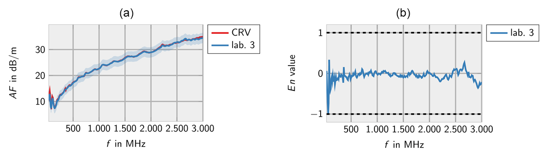
Figure 4Measurements of lab 3 for the Schwarzbeck VULB 9163 (a) and corresponding En values (b).
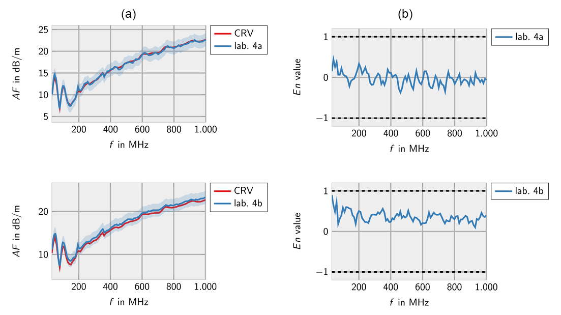
Figure 5Measurements of lab 4 for the Schwarzbeck VULB 9163 (a) and corresponding En values (b). Measurement 4a according to ANSI C63.5 (10 m). Measurement 4b according to ANSI C63.5 (3 m).

Figure 6Measurements of lab 5 for the Schwarzbeck VULB 9163 (a) and corresponding En values (b).
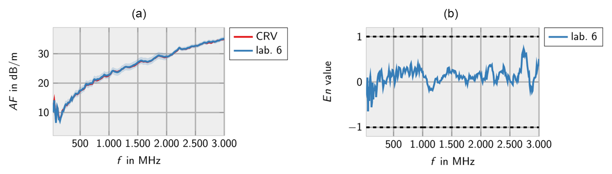
Figure 7Measurements of lab 6 for the Schwarzbeck VULB 9163 (a) and corresponding En values (b).
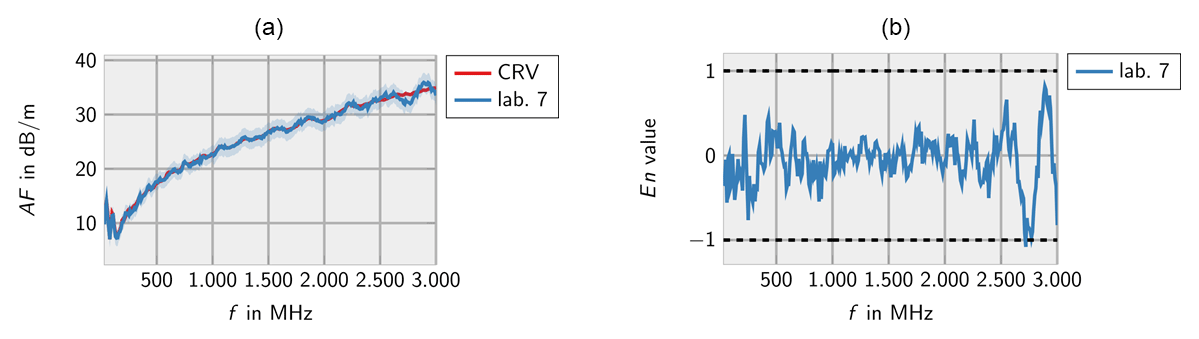
Figure 8Measurements of lab 7 for the Schwarzbeck VULB 9163 (a) and corresponding En values (b).
3.1 Free-space antenna factor
3.1.1 Hybrid antenna (30 MHz–3 GHz)
Figure 1 shows the results of the antenna factor measurements at PTB for the hybrid antenna Schwarzbeck VULB 9163 at the beginning and the end of the intercomparison. The results are consistent within the specified measurement uncertainty, indicating that the antenna properties did not change during the intercomparison.
Figures 2–8 show the results of the participating laboratories. Laboratory 1 and 4 used two different methods to determine the free-space antenna factor. The measurements of lab 1 are considered to be independent. Therefore, both measurements are contributing to the CRV. Measurement 4b has been excluded from the calculation of the CRV in order not to let near-field effects due to the small measurement distance influence the CRV. In this case the En value has been calculated according to Eq. (7).
The decaying trend in measurement 1b shows that the antenna factor is estimated too high at lower frequencies and too low at higher frequencies. This is due to the systematic error in the CRV resulting from some laboratories considering the phase center position in their calculation, only.
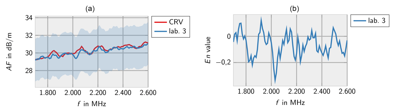
In general, the measurements of all laboratories are consistent with the CRV. Only very few deviations are identified for lab 3 at low frequencies and lab 7 at high frequencies.
3.1.2 Log. per. dipole antenna (650 MHz–8 GHz)
Figure 9 shows the results of the antenna factor measurements at PTB for the logarithmic-periodic antenna Schwarzbeck USLP 9142 at the beginning and the end of the intercomparison. The results are consistent within the specified measurement uncertainty, indicating that the antenna properties did not change during the intercomparison, as well.
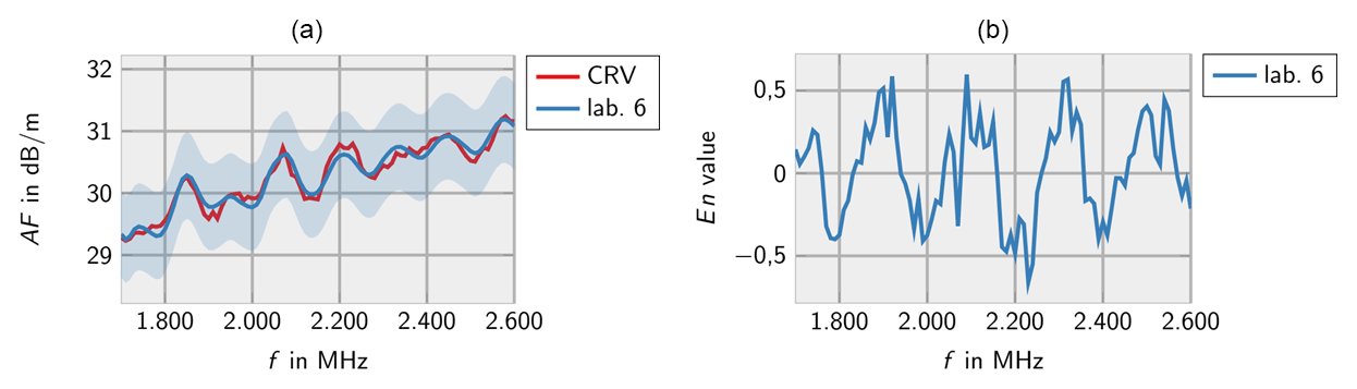
Figures 10–14 show the measurement results from the different laboratories. As before, the results indicate that the laboratories can determine the correct antenna factors within the specified measurement uncertainties independent from the measurement method. Single incompatible measurement results are found below 1000 MHz and at a peak of the antenna factor.
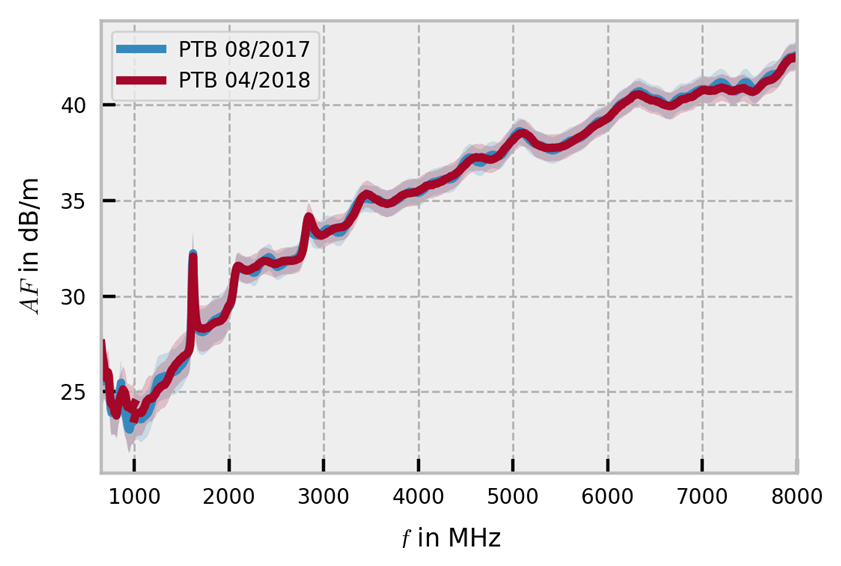
Figure 9Free-space antenna factor of the Schwarzbeck USLP 9142 measured at PTB at the beginning and at the end of the intercomparison.
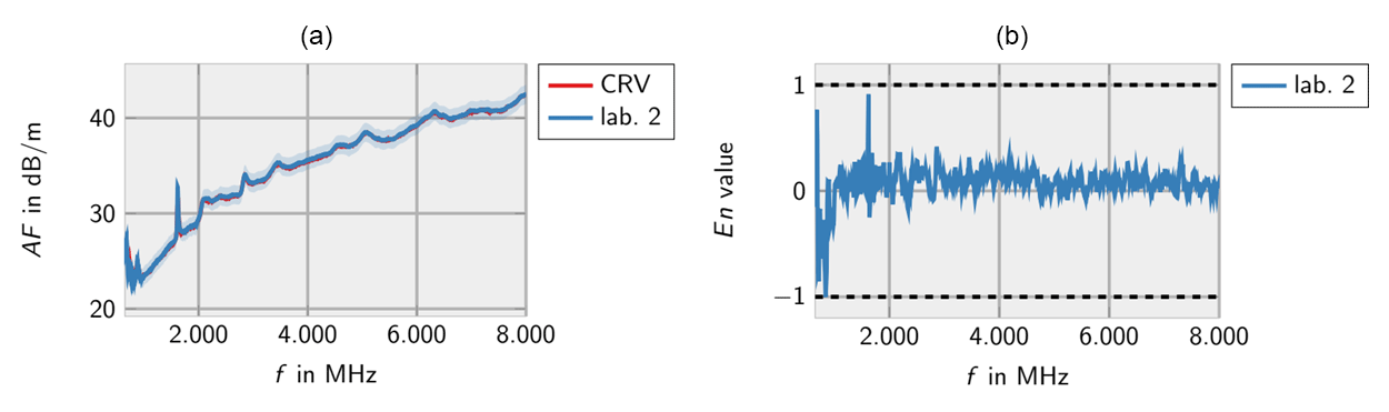
Figure 10Measurements of lab 2 for the Schwarzbeck USLP 9142 (a) and corresponding En values (b).
3.1.3 Open-ended waveguide (1.7 GHz–2.6 GHz)
Figure 15 shows the results of the antenna factor measurements at PTB for the OEWG at the beginning and the end of the intercomparison. Here, the results are consistent, as well, although a better match would have been preferred.
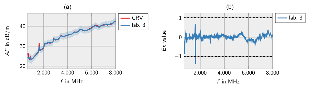
Figure 11Measurements of lab 3 for the Schwarzbeck USLP 9142 (a) and corresponding En values (b).
Figures 16–18 show the measurement results from the different laboratories, which are consistent as well. Unfortunately, only three laboratories measured the OEWG which restricts the informative value of the results.
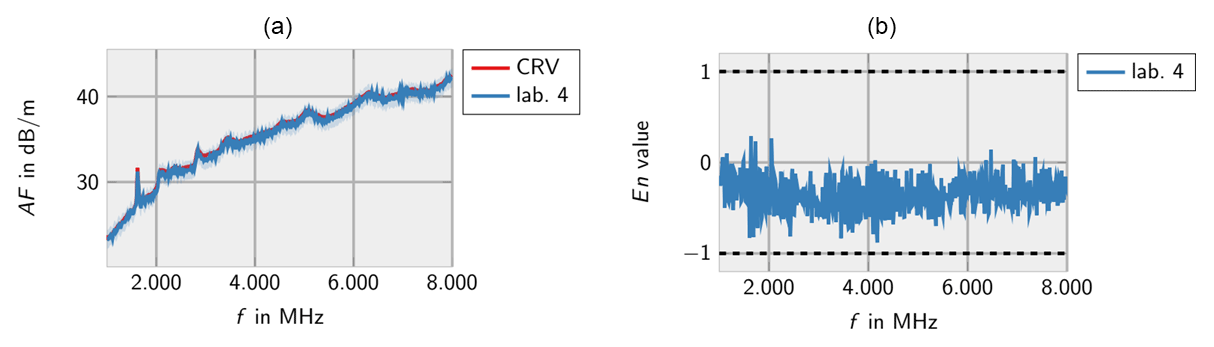
Figure 12Measurements of lab 4 for the Schwarzbeck USLP 9142 (a) and corresponding En values (b).
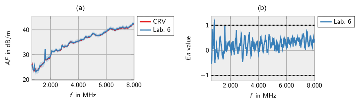
Figure 13Measurements of lab 6 for the Schwarzbeck USLP 9142 (a) and corresponding En values (b).
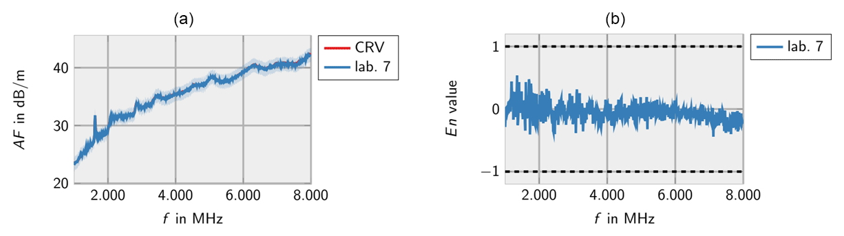
Figure 14Measurements of lab 7 for the Schwarzbeck USLP 9142 (a) and corresponding En values (b).
3.2 Antenna factor according to SAE ARP 958D
3.2.1 Hybrid antenna (30 MHz–3 GHz)
Figure 19 shows the measurement results and En values of the participating laboratories for the hybrid antenna Schwarzbeck VULB 9163 for the 1 m antenna factor according to SAE ARP 958D. While all reported measurements are consistent above 200 MHz, lab 4 reports inconsistent measurement values below 200 MHz and is advised to revise its measurement uncertainty budget.
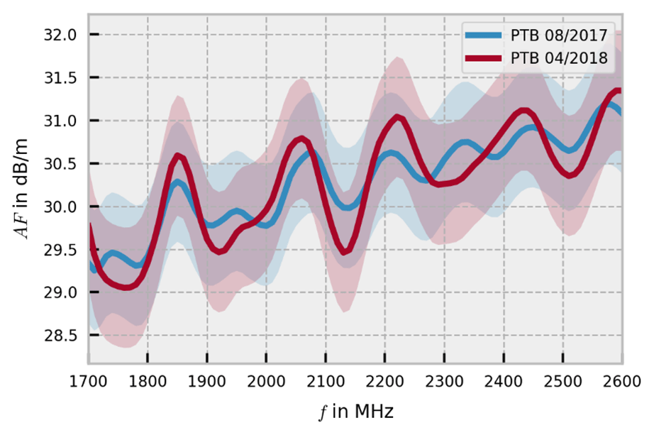
Figure 15Free-space antenna factor of the OEWG measured at PTB at the beginning and at the end of the intercomparison.
3.2.2 Log.-per. dipole antenna (650 MHz–8 GHz)
Figure 20 shows the measurement results and En values of the participating laboratories for the logarithmic-periodic antenna Schwarzbeck USLP 9142 for the 1 m antenna factor according to SAE ARP 958D. Two single incompatible measurement results in the lower frequency range can be explained by statistics.

3.2.3 Open-ended waveguide (1.7 GHz–2.6 GHz)
Figure 21 shows the measurement results and En values of the laboratories 5 and 7 for the OEWG for the 1 m antenna factor according to SAE ARP 958D. The measurement results are consistent, however, the informative value is restricted due to two participants, only.

Figure 19Measurements of lab 2–4 for the 1 m antenna factor according to SAE ARP 958D of the Schwarzbeck VULB 9163 (a) and corresponding En values (b).
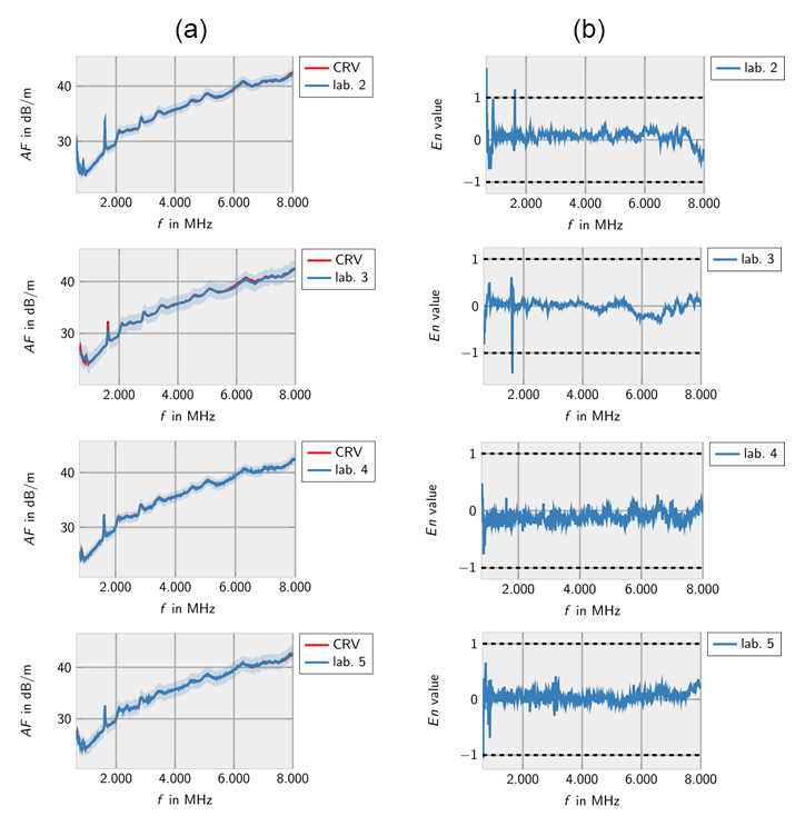
Figure 20Measurements of lab 2–5 for the 1 m antenna factor according to SAE ARP 958D of the Schwarzbeck USLP 9142 (a) and corresponding En values (b).

Figure 21Measurements of lab 5 and 7 for the 1 m antenna factor according to SAE ARP 958D of the OEWG (a) and corresponding En values (b).
The results of the intercomparison are very satisfactory. All laboratories estimate their measurement uncertainty in a realistic way. Only one laboratory should reconsider its measurement uncertainty budget in the lower frequency range. The results obtained for the free-space antenna factor according to the standards IEEE 149, CISPR 16-1-6 and ANSI C63.5 are comparable independent from the method used.
A problem is that some laboratories are considering the position of the phase center in their antenna factor calculation while others do not. This leads to a systematic error of the CRV. While the En value is estimated too large for laboratories that consider the phase center, it is too small for those who do not. Therefore, the comparability of the CRV obtained here to antenna factors determined using near-field methods is restricted.
The underlying data sets are property of the participating laboratories and are not made available to the public.
The intercomparison has been initiated and planed by TK-O and TS. Measurements and data evaluation have been done by DU.
The authors declare that they have no conflict of interest.
This article is part of the special issue “Kleinheubacher
Berichte 2018”. It is a result of the Kleinheubacher Tagung 2018, Miltenberg,
Germany, 24–26 September 2018.
Edited by: Michael Vogt
Reviewed by: two anonymous referees
ANSI C63.5: American National Standard for Electromagnetic Compatibility, Radiated 2 Emission Measurements in Electromagnetic Interference (EMI) Control, Calibration of 3 Antennas (9 kHz to 40 GHz), Institute of Electrical and Electronics Engineers (IEEE), New York, USA, 2017.
ANSI/IEEE 149-1979: IEEE Standard Test Procedures for Antennas, Institute of Electrical and Electronics Engineers (IEEE), New York, USA, December 2008.
CISPR 16-1-6: Specification for radio disturbance and immunity measuring apparatus and 6 methods – Part 1–6: Radio disturbance and immunity measuring apparatus, EMC antenna 7 calibration, 2014.
Cox, M. G.: The evaluation of key comparison data, Metrologia, 39, 589–595, 2002.
DKD-V 2.5: Nationaler Ringvergleich Freiraum- und 1 m-Antennenfaktor August 2017–April 2018, in: Vergleichsbericht DKD-V 2.5, Ausgabe 10/2018, edited by: Ulm, D., Schrader, T., and Kleine-Ostmann, T., Deutscher Kalibrierdienst, available at: https://www.ptb.de/cms/fileadmin/internet/dienstleistungen/dkd/Allgemein/DKD-V_2.5.pdf (last access: 5 February 2019), 2018.
GUM: Evaluation of measurement data – Guide to the expression of uncertainty in measurement, JCGM 100:2008, GUM 1995 with minor corrections, Joint Committee for Guides in Metrology (JCGM) of BIPM, IEC, IFCC, ILAC, ISO, IUPAC, IUPAP and OIML, Paris, France, 2008.
Gustrau, F.: Hochfrequenztechnik – Grundlagen der mobilen Kommunikationstechnik, Carl Hanser Verlag, Dortmund, 2013.
Krystek, M.: Berechnung der Messunsicherheit: Grundlagen und Anleitung für die praktische Anwendung, Beuth Verlag, Berlin, 2012.
PTB-Mitteilungen: The new German Calibration Service (DKD), in: Vol. 124 (2014), English Edition, Physikalisch-Technische Bundesanstalt (PTB), Braunschweig, April 2015.
SAE ARP958D: Electromagnetic Interference Measurement Antennas, Standard Calibration 17 Method, SAE International, Warrendale, USA, 2003.
USLP: USLP 9142 – Log.-Periodische Antenne, available at: http://www.schwarzbeck.de/de/antennen-de/logarithmisch-periodische-breitbandantennen/standard-lpda-de/332-uslp-9142-log-periodische-antenne.html (last access: 5 February 2019), 2018.
VULB: VULB 9163 – TRILOG Breitband Antenne, available at: http://www.schwarzbeck.de/de/component/content/article/47-bikonisch-logarithmisch-periodische-antennen-hybrid/358-vulb-9163-breitband-trilog-antenne.html (last access: 5 February 2019), 2018.