Articles | Volume 17
https://doi.org/10.5194/ars-17-71-2019
19 Sep 2019
 | 19 Sep 2019

Design of leaky-wave antennas with transverse slots for end-fire radiation with optimized radiation efficiency

Thomas Vaupel and Claudius Löcker
Abstract

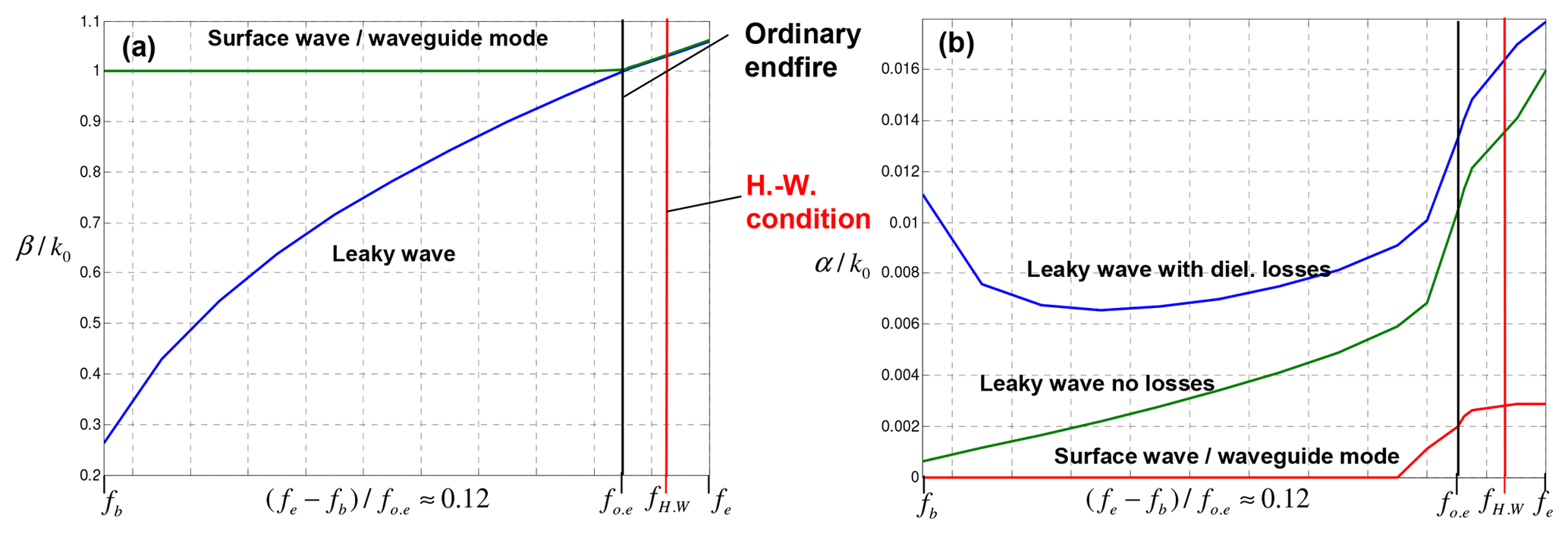
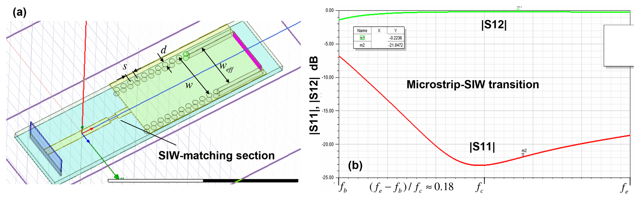
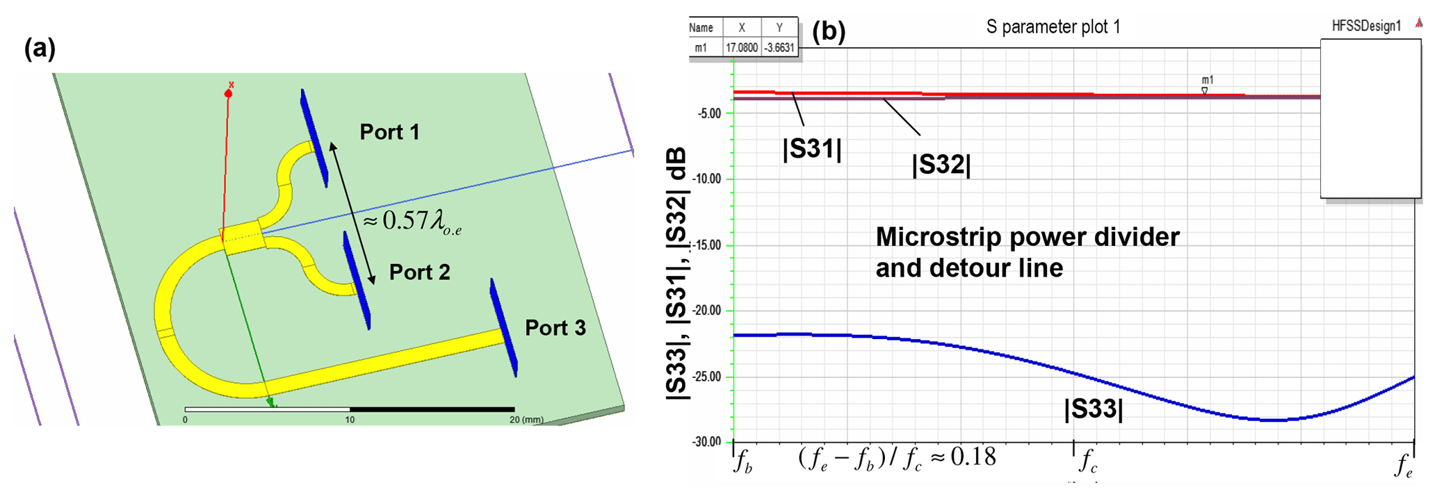
A substrate integrated waveguide (SIW) with transverse slots on the top plane can be used to design an effective leaky-wave antenna with good frequency beam-scanning and platform integration capability. For a main beam near end-fire, the phase constant of the radiating wave must be near to the free space wavenumber or slightly larger. In this context, the modified Hansen-Woodyard condition gives an optimum phase constant to maximize the directivity at end-fire. For the analysis of the wave propagation we have implemented a modal analysis for rectangular waveguides with transverse slots. Near end-fire, three types of modal solutions exists, a leaky improper mode, a surface wave mode and a proper waveguide mode. The leaky mode can reach phase constants larger than the free space wavenumber to fulfill the Hansen-Woodyard condition, but loses strongly its physical significance in this slow wave region, thus the excitation of the leaky-wave becomes negligible there, whereas the proper waveguide mode is dominant but exhibits only a negligible radiation loss leading to a strong drop of the antenna efficiency. Therefore, the optimum efficiency of 86 % for maximizing the gain as proposed in the literature cannot be reached with this kind of leaky wave antenna.

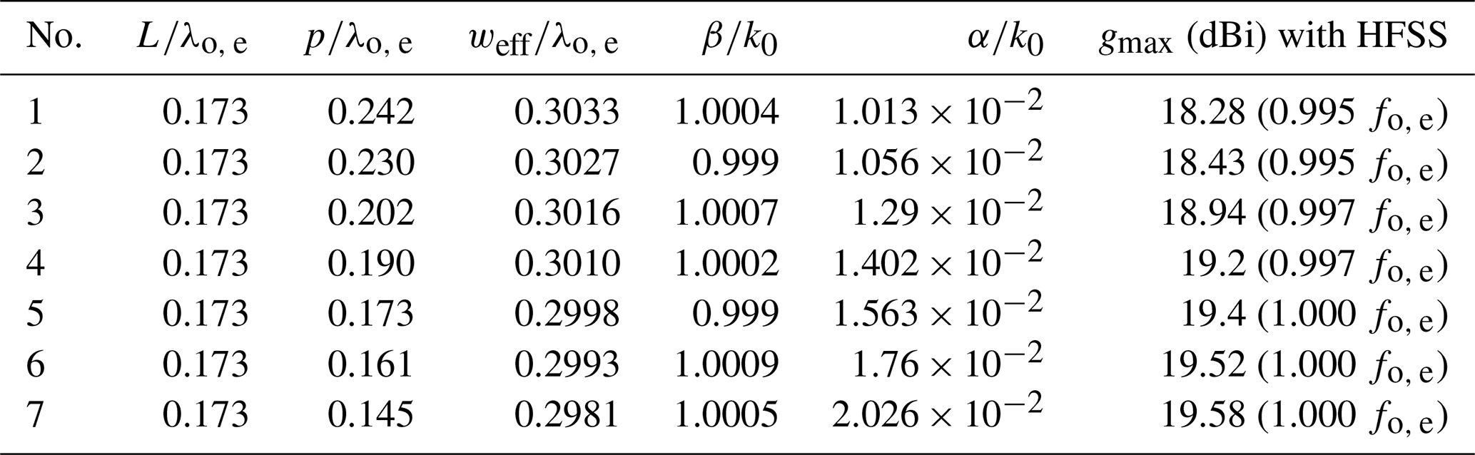
But it will be shown in this contribution by analyzing antenna structures with finite aperture lengths, that the efficiency can reach nearly 100 % if the phase constant of the leaky-wave meets exactly the free space wavenumber (ordinary end-fire condition) and the aperture length is adjusted with regard to the attenuation constant of the leaky-wave from the modal analysis. For a given aperture length, a procedure is outlined to adjust the attenuation constant in several steps at the desired ordinary end-fire frequency to reach maximum gain and efficiency.

https://www.adv-radio-sci.net/17/71/2019/ars-17-71-2019-f01

Figure 1(a) Configuration for the modal analysis. (b) Model in HFSS for analyis of antennas with finite length.

Download

https://www.adv-radio-sci.net/17/71/2019/ars-17-71-2019-f02

Figure 2Modal analysis results of the structure in Fig. 1a.

Download

https://www.adv-radio-sci.net/17/71/2019/ars-17-71-2019-f03

Figure 3Analysis of the structure in Fig. 1b with HFSS.

Download

https://www.adv-radio-sci.net/17/71/2019/ars-17-71-2019-f04

Figure 4(a) S-parameters of the structure Fig. 1b with the values of Table 1. (b) Gain pattern of the structure No. 7.

Download

https://www.adv-radio-sci.net/17/71/2019/ars-17-71-2019-f05

Figure 5Microstrip-SIW transition.

Download

https://www.adv-radio-sci.net/17/71/2019/ars-17-71-2019-f06

Figure 6Microstrip power divider with detour line.

Download

1 Introduction and first design analysis

Figure 1a, shows the configuration with infinite length and filled rectangular waveguide used for the modal analysis in the space domain (Liu and Jackson, 2011). This analysis searches for the complex propagation wavenumber kz=β-jα which sets the corresponding transcendental equation to zero (Eq. 7 in Liu and Jackson, 2011). For this search, we use the downhill-method (Bach, 1969), leading to convergent results typically with around 50 steps. The first design is based on the following values related to a wavelength λo, e, which corresponds to the free space wavenumber at the frequency of ordinary end-fire operation fo, e, see text below. Due to non-disclosure reasons, the exact frequencies (in the Ku-band) and design parameters must not be specified: slot length L=0.16λo,e, slot width W=0.025λo,e, periodicity p=0.15λo,e, b=0.44λo,e, a=weff=0.3λo,e and the dielectric filling εr=3.5. In Fig. 2b, the modal analysis of the propagation constant βk0 is given. For frequencies larger than fo, e, the leaky-wave (blue) and the proper waveguide mode (green) have a β/k0>1. According to O'Connor and Jackson (2011), the (modified) Hansen-Woodyard condition for highest directivity and gain with an aperture length of 20λo,e should be fulfilled for β/k01.023 reached around 1.0076fo,e=fH.W., the frequency where the Hansen-Woodyard condition is fulfilled. According to Fig. 2b, the attenuation constant with dielectric losses reaches α/k0=0.0161 at fH.W. (blue curve at red bar). But if the structure is analyzed with a finite length as in Fig. 1b, the attenuation drops down for frequencies beyond the ordinary end-fire operation.

https://www.adv-radio-sci.net/17/71/2019/ars-17-71-2019-f07

Figure 7(a) Structure with two antenna branches. (b) Comparison of peak gain of structures with two and one antenna branches.

Download

Table 1Stepwise increasing of the attenuation constant at ordinary end-fire.

Download Print Version | Download XLSX

This can be recognized by the behaviour of |S12| reaching a minimum exactly at the ordinary end-fire frequency with −9.21 dB and a radiation efficiency of er=88 % and then increases strongly to −4.73 dB (er=66 %) where the modified Hansen-Woodyard condition should be fulfilled (see Fig. 3b).

This is due to the fact, that the leaky mode becomes unphysical beyond end-fire and the proper waveguide mode becomes dominant with a low attenuation only due to dielectric and metallic losses, thus |S12| becomes larger.

2 Gain improvement by maximizing the efficiency

This can also be observed in Fig. 2b, where the red curve shows only a small increase somewhat before fo, e. Figure 3b shows the radiation pattern at ordinary end-fire (blue) with a maximum gain of 18.19 dBi, whereas the gain curve at the Hansen-Woodyard condition shows only a maximum of 14.93 dBi mainly due to the lower radiation efficiency. According to Liu and Jackson (2012), the contribution of the leaky-wave drops down to about 10 % at ordinary end-fire, whereas the surface-wave mode may show a maximum contribution around this frequency.

Obviously the leaky-wave is transformed into the surface-wave over the aperture length in such a way that the attenuation constant for the leaky-wave derived from the modal analysis is still valid for the radiating mechanism of both leaky and surface-wave mode up to the frequency of ordinary end-fire. Since the excitation of the surface wave drops down beyond the ordinary end-fire frequency, the efficiency of 86 % at the modified Hansen-Woodyard condition for gain maximization as proposed in O'Connor and Jackson (2010) cannot be reached. Therefore we propose as follows a gain improvement at the ordinary end-fire frequency by a procedure of step-wise increasing the attenuation constant to maximize the efficiency derived by

(1) ε r = 1 - S 12 2

and to maximize the gain at ordinary end-fire.

The attenuation constant can be increased by enlarging the slot length and/or the slot width and/or decreasing the slot periodicity. But with fixed width of the waveguide, also the values of βk0 are increasing. This can be compensated by decreasing the width of the waveguide. A good estimation for the modification of the width by Δweff is given by (similar as in Liu and Jackson, 2014)

(2) Δ w eff π k 0 2 ε r - β 2 ( L , W , w eff , p ) - π k 0 2 ε r - β desired 2

where β(L,W,weff,p) is the propagation constant with the current weff and βdesired is the desired propagation constant for the given L,W,p of the slots. However, in most cases it is faster to use a linear interpolation to find the exact weff: If β is too large, weff is slightly decreased and from the new value for β, the exact weff can be often determined with one interpolation step. We have now implemented this method as an iterative procedure in our modal analysis program showing typically a very good convergence in 2 to 4 steps with a maximum deviation for βdesiredk0 of 0.001.

In Table 1, the αk0 with the parameter set No. 1 is doubled in 6 steps only by reduction of the periodicity p (L=0.173λo,e, and W=0.0254λo,e remain constant), keeping the βk0 at the ordinary end-fire value for the constant frequency fo, e using the modal analysis and the interpolation sketched above. The values for the maximum gain are derived with HFSS with the aperture length of the structure in Fig. 1b. Further results of the simulations with HFSS are given in Fig. 4. The minima of |S12| become monotonously smaller, for the parameter sets No. 1 to No. 4 we have still a small frequency offset, but from parameter set No. 5 the frequency with maximum attenuation at the desired frequency fo, e is also met by the HFSS-simulations. With Eq. (1) we get an efficiency of 97 % for No. 6 and 99 % for No. 7, thus a further increase of the attenuation constant is not meaningful and would lead to a gain reduction. Figure 4b shows the gain pattern of No. 7 for different frequencies .

The gain is, depending on frequency, up to 1.4 dBi higher for No. 7 compared with the parameter set No. 1. A radiation exactly in end-fire direction is not possible due to diffraction effects of the finite groundplanes.

Since the antennas are fabricated in SIW-technology, we still need a SI-waveguide with width w and the same propagation constant as the rectangular waveguide with width weff=a (see also Fig. 5a). In many cases the formula (e.g. Kumar and Jadhav, 2012)

(3) w = w eff + d 2 / ( 0.95 s )

Equation (3) is not correct enough. With d=0.6 mm and s=0.8815 mm we get w=0.3229λo,e with Eq. (3) what leads to a minimum of |S12| around 100 MHz higher than the desired fo, e. But if we take the formula

(4) w = w eq + s ( 0.766 e 0.4482 d / s - 1.176 e - 1.214 d / s ) ,

derived in Kordiboroujeni and Bornemann (2013), we get w=0.3248λo,e slightly higher, the minimum is shifted to the desired fo, e again and we get the same gain behaviour as with a rectangular waveguide.

For the practical implementation we need also a microstrip-SIW transition, which is sketched in Fig. 5, showing a good matching behavior with low losses and a bandwidth of about 18 %.

3 Antennas with two branches

To reach a higher gain also for frequencies below end-fire, we have also examined structures with two antenna branches. In this context we need a power divider with low losses. A suitable microstrip divider with additional detour line is outlined in Fig. 6 with the input port 3. We have used rounded bends to minimize the parasitic radiation leading to losses of only about 0.6 dB (Weisshaar and Tripathi, 1990). A power divider with mitered bends could be optimized for a good matching behaviour, but the losses amount to about 1.5 dB mainly due to the parasitic radiation of the mitered bends. A structure with two antenna branches with a center distance of 10 mm is given in Fig. 7a.

Figure 7b shows the peak gain comparison with one and two branches. Due to mechanical constraints, the SMP-connector must be located alongside the branches thus the additional detour line is needed. The SMP-connector is linked to the microstrip line with an additional matching section .

The maximum gain of the structure with one branch drops down to 18.4 dBi at fo, e (compared with the structure No. 7 with 19.58 dBi) due to the additional detour line, microstrip-SIW transition and the SMP-connector. But with two branches we get a maximum gain of 19.42 dBi and for frequencies below end-fire, the peak gain is typically 3 dB higher compared with the structure with only one branch.

4 Conclusions

Leaky-wave antennas in SIW-technology with transverse slots are a good candidate, if a frequency scanning capability up to end-fire and a cheap fabrication is desired. To increase the directivity and gain at end-fire operation, the (modified) Hansen-Woodyard condition may be applied. To fulfill this condition, the propagation constant of the radiating mode must be slightly higher than the free space wavenumber. However, in this slow wave region the leaky-wave becomes unphysical and also the excitation of the surface wave mode drops down strongly beyond the ordinary end-fire operation. But it could be found, that the leaky-wave is transformed into the surface wave at the frequency of ordinary end-fire and that for the radiation loss computation along the aperture still the attenuation constant of the leaky-wave can be used which is derived from a modal analysis based on rectangular waveguides. With this modal analysis, we have outlined a procedure to stepwise increase the attenuation constant e.g. by decreasing the periodicity of the slots and decreasing the width of the waveguide to get a radiation efficiency of about 99 % adjusted to the length of the aperture. After a careful transformation of the rectangular waveguide into a SIW together with an efficient microstrip-SIW transition, a cheap fabrication is possible. With the use of power dividers with low losses, structures with two antenna branches can be designed leading to a gain improvement also for frequencies below end-fire operation.

Data availability

There are no underlying research data for the presented work due to non-disclosure reasons. The results can be reproduced with the design methods and equations given in the paper.

Competing interests

The authors declare that they have no conflict of interest.

Special issue statement

This article is part of the special issue “Kleinheubacher Berichte 2018”. It is a result of the Kleinheubacher Tagung 2018, Miltenberg, Germany, 24–26 September 2018.

Review statement

This paper was edited by Thomas Eibert and reviewed by three anonymous referees.

References

Bach, H.: On the downhill method, Commun. ACM, 12, 675–677, 1969. 

Kordiboroujeni, Z. and Bornemann, J.: Designing the Width of Substrate Integrated Waveguide Structures, IEEE Microw. Wirel. Co., 23, 518–520, 2013. 

Kumar, H., Jadhav, R., and Ranade, S.: A Review on Substrate Integrated Waveguide and its Microstrip Interconnect, IOSR Journal of Electronics and Communication Eng. (IOSR-JECE), 3, 36–40, 2012. 

Liu, J. L., Jackson, D. R., and Long. Y.: Modal Analysis of Dielectric-Filled Rectangular Waveguide With Transverse Slots, IEEE Trans. Antennas Prop., 59, 3194–3203, 2011. 

Liu, J. L., Jackson, D. R., and Long, Y.: Substrate Integrated Waveguide (SIW) Leaky-Wave Antenna With Transverse Slots, IEEE Trans. Antennas Prop., 60, 20–29, 2012. 

Liu, J. L., Jackson, D. R., Li, Y., Zhang, C., and Long, Y.: Investigations of SIW Leaky-Wave Antenna for End-fire-Radiation With Narrow Beam and Sidelobe Suppression, IEEE Trans. Antennas Prop., 62, 4489–4497, 2014. 

O'Connor, E. M., Jackson, D. R., and Long, S. A.: Extension of the Hansen-Woodyard Condition for End-fire Leaky-Wave Antennas, IEEE Antenn. Wirel. Pr., 9, 1201–2104, 2010. 

Weisshaar, A. and Tripathi, V. K.: Perturbation Analysis and Modeling of Curved Microstrip Bends, IEEE Trans. Microwave Theory Techn., 38, 1449–1454, 1990. 

Download
Short summary
A substrate integrated waveguide (SIW) replacing a costly rectangular waveguide is used with transverse slots edged in the top cover of the SIW as effective leaky-wave antenna with radiation direction parallel to the antenna (end-fire) until to 60 degree upwards by frequency scanning. The efficiency is optimized by a procedure leading to a 99 per cent efficiency at end-fire. With special feeding and power dividing circuits, a two-branch antenna could be designed with a further improved gain.