 | 17 Dec 2021
A MIMO Radar System based on Fractal Antenna Arrays for Level Measurement Applications
Michael Vogt
Ilona Rolfes
In this contribution, the design of a multiple-input multiple-output (MIMO) radar system in 77–81 GHz range with 18 transmitting antennas and 24 receiving antennas for measuring the height profile of bulk solids in silos, is presented and discussed. The antenna array topologies are optimized by utilizing space filling fractals in order to approximate a circular shaped antenna array on a hexagonal grid. The proposed MIMO radar system achieves an angular resolution of 3.1∘ for a maximum scanning angle of and a side lobe suppression of 12.6 dB. The performance of the system has been evaluated by test measurements on a sand heap, showing an improved measurement accuracy compared to conventional radar level systems.
- Article
(1995 KB) - Full-text XML
- BibTeX
- EndNote


In the context of level measurement, determining the volume of bulk solids in silos by means of radar is a challenging task, due to the complex spatial structure of the bulk solid heap (Brooker et al., 2006; Nienhaus et al., 2009). The MIMO radar concept is utilized in a variety of 3D imaging scenarios, like whole-body imaging or remote sensing (Ahmed et al., 2009; Ender and Klare, 2009; Klare et al., 2010). Since integrated radar chips are emerging in automotive applications, MIMO radar systems are appropriate to improve the accuracy of height profile measurements of bulk solids by realizing scanning radar systems using digital beam forming (Dahl et al., 2017a; Nienhaus et al., 2007; Zankl et al., 2015). As the performance of a MIMO radar system is mainly limited by the number of transmit and receive channels, the topology of the transmit and receive antenna array are an important factor. Fractal antenna arrays can advantageously be used to optimize the angular resolution and side lobe level of a MIMO radar system. This is achieved by combining sub arrays based on space-filling fractals in order to approximate circular shaped arrays on a hexagonal grid (Dahl et al., 2017b; Werner et al., 2004). In the work presented here, fractal arrays have been adapted for realizing MIMO radar systems and the developed concept has been used and validated for radar level measurement applications.
In the following, time-division multiplexed MIMO radar systems with spatially separated antenna arrays for transmit and receive are considered. The angular resolution Δθ of a MIMO radar system depends on the two-way radiation pattern which is given by the virtual array factor AFV, expressed in spherical coordinates using the polar angle θ and the azimuthal angle φ. It can be obtained by multiplying the array factor AFTx of the transmitting array with the array factor AFRx of the receiving array (Fishler et al., 2004):
As illustrated in Fig. 1, the virtual array factor AFV of the MIMO radar corresponds to a virtual antenna array, which is given by the convolution of the transmitting array with the receiving array (Fishler et al., 2004). The radar echo with each transmit-receive combination is assigned to one virtual antenna element. By applying two-dimensional digital beam forming and a range compression to the echo data represented in the virtual antenna array, a 3D radar image is reconstructed in spherical coordinates. After interpolation to Cartesian coordinates, the surface profile of the bulk solid heap can be reconstructed and the filling volume can be measured (Dahl et al., 2015a).

Figure 1MIMO radar concept: Virtual array formed by the convolution of the transmit array and the receive array.
In general, the array factor AF of a planar antenna array, consisting of N discrete elements, depends on the element positions (xn,yn), the complex element weights wn, and the wave number , with the frequency f of the radiated electromagnetic waves (Volakis, 2007). The polar and azimuthal angles θ and φ,respectively, are transformed into -coordinates:
The array factor AF can then be written as:
In order to steer the main lobe to a direction (u0,v0), the complex weights wn in the array factor AF have to be chosen as follows:
In the following, all array factors are analyzed with the main lobe steered to .
For a MIMO radar system with given numbers of transmit and receive antennas NTx and NRx, respectively, the virtual array with virtual antenna elements can be optimized by approximating a circular shaped array on a hexagonal grid in order to maximize the virtual aperture diameter (Dahl et al., 2015b). As a result, the side lobe suppression SLS and the angular resolution Δθ of the virtual array factor AFV are improved, compared to conventional MIMO radar configurations based on perpendicular linear antenna arrays (Dahl et al., 2015b; Zhuge and Yarovoy, 2012). In the following, space filling Fudgeflake and Gosper island fractals on a hexagonal grid are utilized for this purpose (Dahl et al., 2016, 2017b).
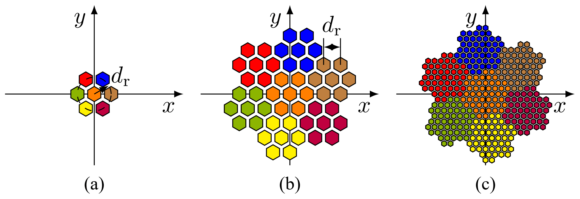
2.1 Fudgeflake fractal
As shown in Fig. 2a, the first stage (L=1) of the Fudgeflake fractal can be used to combine three antenna elements to a regular triangle on a hexagonal grid (Werner et al., 2004).

The corresponding array factor AFF,1 can be written as follows using the radial element spacing dr:
As illustrated in Fig. 2, higher stages of the fractal can be formed by combining first stages of the fractal in a self-similar way (Dahl et al., 2017b). The array factor AFF,L of the fractal array in a stage L can be expressed by the product of scaled an rotated replicas of the first stage array factor AFF,1:
The rotation angle of the array is proportional to the stage l:
The scaling of the element spacing dr increases with increasing number of elements NF,l of the corresponding stage l:
2.2 Gosper island fractal
According to Fig. 3a, the first stage of the Gosper island fractal combines six antenna elements to a regular hexagon with an additional element in the center (Werner et al., 2003).
The corresponding array factor AFG,1 can be written as:
The higher stages of the Gosper island fractal can be created by combining multiple first stages of the fractal, see Fig. 3 (Dahl et al., 2017b). In analogy to Eqs. (7)–(11), the array factor AFG,L in a stage L of the Gosper island fractal can be written as:
with
In addition, both fractals can be combined to construct MIMO radar systems with circularly shaped virtual antenna arrays on a hexagonal grid (Dahl et al., 2017b). In order to avoid grating lobes, the element spacing dr in the virtual array has to be chosen according to the minimum wavelength λmin and the maximum steering angle θmax:
A MIMO radar system with six Texas Instruments IWR1443 MIMO radar chips, each providing 3 transmit and 4 receive channels, has been realized, see Fig. 4, resulting in NTx=18 transmit antennas and NRx=24 receive antennas.

Figure 4Realized MIMO radar system: (a) Antenna elements on the front side and (b) MIMO radar chips on the back side.
In the chips the frequency modulated continuous wave (FMCW) radar concept is realized. Time-division multiplexing is utilized for all 18 transmit channels and the receive channels are operated simultaneously. With a chirp duration of 194.1 µs the data acquisition for all transmit and receive combinations can be achieved in 8 ms. The measurement rate of the demonstrator system is limited by the data transfer and the signal processing on a personal computer to approximately 4 min and can be further improved by utilizing digital signal processors. By operating in the 77–81 GHz frequency range, a range resolution ΔR=37.5 mm is achieved. Assuming a homodyne receiver architecture, the maximum unambiguous range of Rua is given by the number of complex samples NIF=1024 for each intermediate frequency signal and the range resolution ΔR:
Aperture coupled patch antenna array elements fed by micro strip lines with an element gain GE=8.2 dBi have been realized (Buck and Pozar, 1986). Each of the virtual antenna elements corresponds to a specific transmit and receive combination.
3.1 Fractal array topology
The concept of fractal antenna arrays has been applied for the design of a compact circularly shaped virtual array on a hexagonal grid with an aperture diameter of 50 mm. An antenna spacing dr=2.5 mm is used to allow for a maximum steering angle , according to Eq. (18). As shown in Fig. 5a, a combination of the first stage of the Fudgeflake fractal and the first stage of the Gosper island is used for the transmitting array. The antenna elements at the center have been removed in order to allow for a compact alignment with the receiving array, as shown in Fig. 4a.
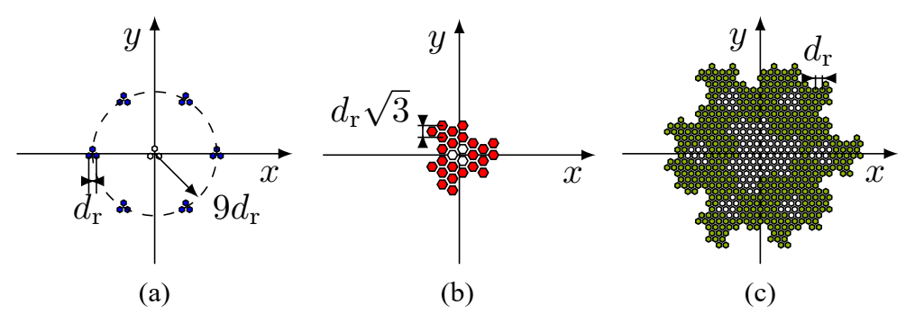
Figure 5Fractal MIMO concept: (a) Transmitting array, (b) receiving array, and (c) corresponding virtual array. The white elements have been removed in order to adjust the number of transmit- and receive antennas.
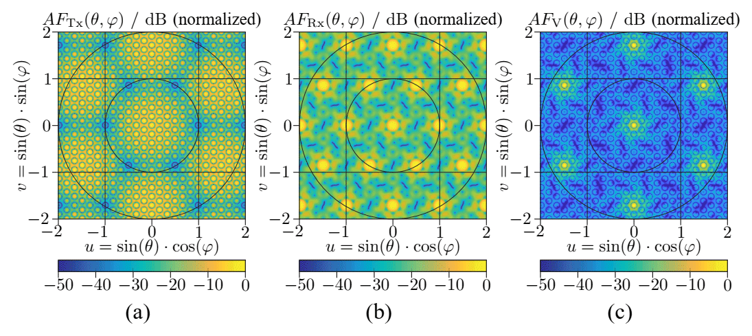
Figure 6Fractal MIMO concept: (a) Transmitting array factor, (b) receiving array factor, and (c) virtual array factor.
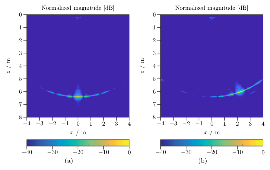
Figure 7Radar images in a cross section y=0 of a corner reflector positioned at two different aspect angles: (a) and (b) .
Figure 6 shows that the grating lobes in the transmit array factor AFTx are suppressed by the zeros of receive array factor AFRx and vice versa.
The resulting virtual array factor AFV shows no disturbing grating lobes any more, and an angular resolution and a side lobe suppression SLS =12.6 dB, is achieved.
The range resolution ΔR, the angular resolution Δθ and a side lobe suppression SLS of the proposed MIMO radar system have been evaluated in a single target scenario. Therefore, a triangular corner reflector with a edge length of 25 cm has been positioned in an anechoic chamber at a range of 6.4 m for two different aspect angles and . A cross section of the corresponding radar images are shown in Fig. 7, achieving a range resolution ΔR=36 mm.
Figure 8 shows the radar images in a polar cross section in order to evaluate the side lobe pattern at the target range R=6.4 m.

Figure 8Radar images in a polar cross section R=6.4 m of a corner reflector positioned at two different aspect angles: (a) and (b) .

Figure 9(a) Measurement scenario and (b) corresponding radar image in a vertical cross section x=0.
For an aspect angle of an angular resolution and a side lobe suppression SLS =12.6 dB are achieved. As as expected, side lobe pattern corresponds to the virtual array factor AFV, see Fig. 6c. For an aspect angle of , the side lobe suppression SLS is reduced by 2.1 dB and the angular resolution Δθ is increased to 3.4∘. This is mainly caused by the radiation pattern of the patch antenna elements and leads to a minor degradation in the measurement performance for higher aspects angles θ.
The proposed MIMO radar system has been evaluated in a realistic measurement scenario, consisting of a sand heap with a height of 0.8 m. As shown in Fig. 9a, the radar system has been mounted 2.5 m above the heap and the echo data from all transmit and receive combinations has been processed to reconstruct 3D radar images. In Fig. 9b, a vertical cross section is shown, allowing for reconstruction of the heap. The crosstalk between the antenna elements along with the wave propagation across the printed circuit board are causing clutter in the radar image for ranges below 50 cm.
In this paper, the design of a MIMO radar system with 18 transmit and 24 receive antennas has been presented. It has been shown that array topologies based on space filling fractals can be utilized to approximate a virtual aperture with a circular shape and to improve the side lobe suppression as well as the angular resolution. The performance of a sparse fractal MIMO array has been proven in a typical scenario, resulting in an improved accuracy for level measurement applications.
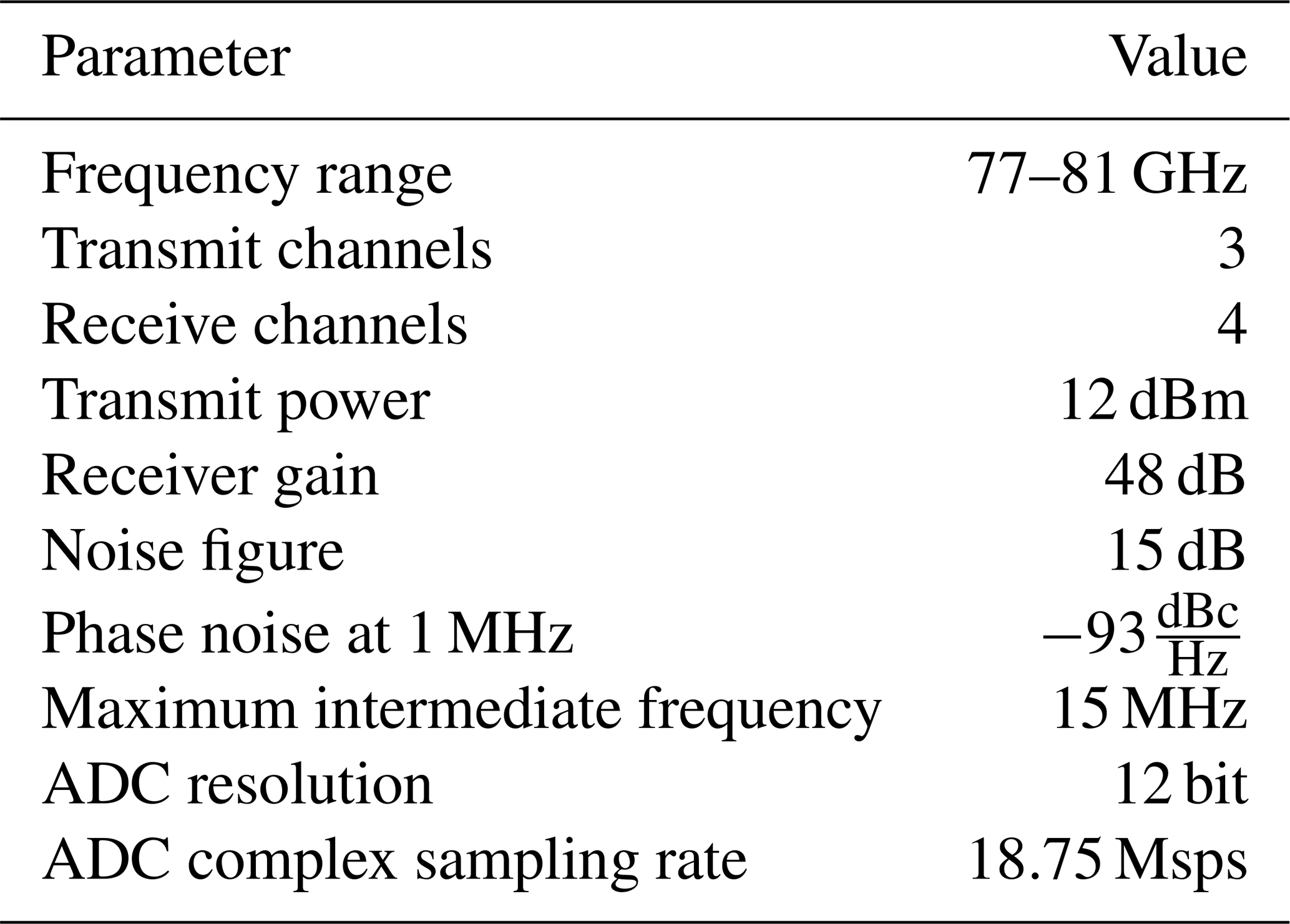
The Texas Instruments IWR1443 is a integrated MIMO radar chip realized in a 45 nm RFCMOS process. It allows for a compact realization of MIMO radar systems by combining analog FMCW radar transceivers with digital signal processors. In a master slave configuration, the FMCW ramp can be distributed to multiple slave chips in 19.25–20.25 GHz range. An additional pulse is emitted by the master in order to synchronize the ramp start time between the analog-to-digital converters (ADC). The specification of the IWR1443 radar chip according to the data sheet is shown in Table A1.
Data used in this paper is available upon request: Christoph Dahl (christoph.dahl@rub.de).
CD elaborated the concept for the research subject, performed the measurements, and wrote the paper. IR and MV have been supervising the entire process and performed the final review.
The authors declare that they have no conflict of interest.
Publisher's note: Copernicus Publications remains neutral with regard to jurisdictional claims in published maps and institutional affiliations.
This article is part of the special issue “Kleinheubacher Berichte 2020”.
This paper was edited by Madhu Chandra and reviewed by two anonymous referees.
Ahmed, S., Schiess, A., and Schmidt, L.: Near field mm-wave imaging with multistatic sparse 2d-arrays, in: European Radar Conference (EuRAD), 180–183, 2009. a
Brooker, G., Scheding, S., Maclean, A., Hennessy, R., Lobsey, C., and Widzyk-Capehart, E.: Millimetre Wave Radar Vision for the Mining Industry, in: IEEE Conference on Sensors, https://doi.org/10.1109/icsens.2007.355472, 2006. a
Buck, A. and Pozar, D.: Aperture-coupled microstrip antenna with a perpendicular feed, Electron. Lett., 22, 125, https://doi.org/10.1049/el:19860087, 1986. a
Dahl, C., Vogt, M., and Rolfes, I.: A two-dimensional radar simulator for level measurement of bulk material in silos, in: German Microwave Conference (GeMiC), 221–224, https://doi.org/10.1109/gemic.2015.7107793, 2015a. a
Dahl, C., Vogt, M., and Rolfes, I.: Comparison of virtual arrays for mimo radar applications based on hexagonal configurations, in: European Radar Conference (EuRAD), 417–420, https://doi.org/10.1109/EuRAD.2015.7346326, 2015b. a, b
Dahl, C., Vogt, M., and Rolfes, I.: MIMO radar concepts based on antenna arrays with fractal boundaries, in: European Radar Conference (EuRAD), 41–44, 2016. a
Dahl, C., Rolfes, I., and Vogt, M.: Investigation of fractal MIMO concepts for radar imaging of bulk solids, in: European Radar Conference (EURAD), 134–137, https://doi.org/10.23919/EURAD.2017.8249165, 2017a. a
Dahl, C., Vogt, M., and Rolfes, I.: Fractal antenna arrays for MIMO radar applications, Int. J. Microw. Wirel. T., 9, 2019–2028, https://doi.org/10.1017/s1759078717001015, 2017b. a, b, c, d, e
Ender, J. H. G. and Klare, J.: System architectures and algorithms for radar imaging by MIMO-SAR, in: IEEE Radar Conference, https://doi.org/10.1109/radar.2009.4976997, 2009. a
Fishler, E., Haimovich, A., Blum, R., Chizhik, D., Cimini, L., and Valenzuela, R.: MIMO radar: an idea whose time has come, in: IEEE Radar Conference, https://doi.org/10.1109/nrc.2004.1316398, 2004. a, b
Klare, J., Saalmann, O., Wilden, H., and Brenner, A. R.: Environmental monitoring with the imaging MIMO radars MIRA-CLE and MIRA-CLE X, in: IEEE International Geoscience and Remote Sensing Symposium, https://doi.org/10.1109/igarss.2010.5651824, 2010. a
Nienhaus, K., Winkel, R., Mayer, W., Gronau, A., and Menzel, W.: An experimental study on using electronically scanning microwave radar systems on surface mining machines, in: IEEE Radar Conference, 509–512, https://doi.org/10.1109/RADAR.2007.374269, 2007. a
Nienhaus, K., Hahn, M., and Winkel, R.: Wireless sensing applications in the mining and minerals industry, in: IEEE MTT-S International Microwave Workshop on Wireless Sensing, Local Positioning, and RFID, https://doi.org/10.1109/imws2.2009.5307897, 2009. a
Volakis, J.: Antenna engineering handbook, John L. Volakis 2007, McGraw-Hill Education, ISBN: 9780071475747, chap. 3, p. 3, 2007. a
Werner, D., Kuhirun, W., and Werner, P.: The peano-gosper fractal array, IEEE T. Antenn. Propag., 51, 2063–2072, https://doi.org/10.1109/TAP.2003.815411, 2003. a
Werner, D., Kuhirun, W., and Werner, P.: Fractile arrays: a new class of tiled arrays with fractal boundaries, IEEE T. Antenn. Propag., 52, 2008–2018, https://doi.org/10.1109/TAP.2004.832327, 2004. a, b
Zankl, D., Schuster, S., Feger, R., Stelzer, A., Scheiblhofer, S., Schmid, C., Ossberger, G., Stegfellner, L., Lengauer, G., Feilmayr, C., Lackner, B., and Burgler, T.: Blastdar – A large radar sensor array system for blast furnace burden surface imaging, IEEE Sens. J., 15, 5893–5909, https://doi.org/10.1109/JSEN.2015.2445494, 2015. a
Zhuge, X. and Yarovoy, A.: Study on two-dimensional sparse mimo uwb arrays for high resolution near-field imaging, IEEE T. Antenn. Propag., 60, 4173–4182, https://doi.org/10.1109/TAP.2012.2207031, 2012. a