 | 17 Dec 2021
Communication Performance vs. Implementation Trade-offs of Interpolation Techniques for FFT-Based Carrier Synchronization exemplified on DVB-RCS2
Oliver Griebel
Uwe Wasenmüller
Norbert Wehn
Carrier synchronization is a crucial part of any wireless receiver, which is required due to frequency and phase offset. In case of transmission in a Time Division Multiple Access system the carrier synchronization has to be carried out for every burst separately. The DVB-RCS2 standard specifies a large variety of reference burst types with very limited known symbols. For each of these types a thorough exploration of different synchronization algorithms is required to find a trade-off between a good communication performance at very low Signal to Noise Ratio (SNR) and an efficient hardware implementation.
A state-of-the-art algorithm for carrier synchronization is based on the so called Fast Fourier Transformation (FFT). An inherit limitation for the precision of frequency estimation is given by the FFT point size. To counteract this limitation, the FFT point size must be increased. In this paper we extensively compare two possible interpolation techniques for FFT results in three FFT-based carrier synchronization methods. These are applied to various reference burst types specified in the DVB-RCS2 standard. The trade-offs of these combinations are identified with a special focus on hardware implementation efficiency. Furthermore, we present a flexible IP core which can process the three synchronization methods in an efficient way and analyze its implementation complexity and throughput on a Xilinx Kintex FPGA.
- Article
(2422 KB) - Full-text XML
- BibTeX
- EndNote


The transmission of data over a wireless channel results in frequency and phase offsets. The frequency offset is caused by the imperfections of the different oscillators in transmitter and receiver, which will always deviate from the nominal value. Furthermore, the Doppler effect of moving objects results in a frequency offset. The phase shift between transmitter and receiver occurs by the unknown distance between those. Therefore, carrier synchronization is required in wireless receivers. It performs the estimation of the unknown frequency offset and unknown phase offset and corrects the received signal according to the estimated values. In case of a scenario with different transmitters for a receiver, e.g., a Time Division Multiple Access (TDMA) system, the carrier synchronization has to be carried out separately for every burst.
Carrier synchronization on burst structured data transmission can be exemplified on Second Generation Digital Video Broadcasting – Return Channel Satellite (DVB-RCS2). A Joint Technical Committee (JTC) specified this as part of an open standard initially in 2011 and recently revised it, cf. JTC (2012) and JTC (2020a), respectively. This standard applies broad band interactive connections via air interface. Therefore, it utilizes two transmission paths, the forward channel from the network control center to the return channel satellite terminal, and a return channel reversing this path. This return channel has a Multi-Frequency-TDMA channel structure with bursts containing known symbols to perform carrier synchronization. On the physical layer the bursts are modulated by different schemes: Binary Phase-Shift Keying (BPSK), Quadrature Phase-Shift Keying (QPSK), 8-Phase-Shift Keying (8-PSK), 16-Quadrature Amplitude Modulation (16-QAM). 16-state duo-binary Turbo Codes (TC) are applied to support Forward Error Correction (FEC) capability, cf. Douillard and Berrou (2005). Additionally, dynamic operation is provided for rapid changes to the time slot parameters for better power/bandwidth efficiency compared to its preceding standard DVB-RCS.
The DVB-RCS2 receiver knows the transmission burst types in advance, which is used to implement dynamic operation. Those bursts types are constructed by adding known symbols between the payload symbols. Using the in advance known symbols allows the receiver to detect the burst and synchronize the carrier phase and frequency offsets. There are three burst type formats defined by the DVB-RCS2 standard, cf. JTC (2020b), with different location of known symbols which are exemplified in Fig. 1. Each burst format contains preamble symbols, two of them are pilotless. Figure 1a shows a preamble only burst while Fig. 1b shows a pre- and postamble assisted burst. The standard specifies 8 and 7 burst types of these burst formats, respectively. Figure 1c depicts a pilot symbol assisted burst format in addition to pre- and postamble symbols, for which 25 burst types are specified. Each type varies in the known symbol pattern and pre-/postamble length. The pilot blocks are evenly distributed between the payload symbols. Though, they vary in interval, content and repetition.
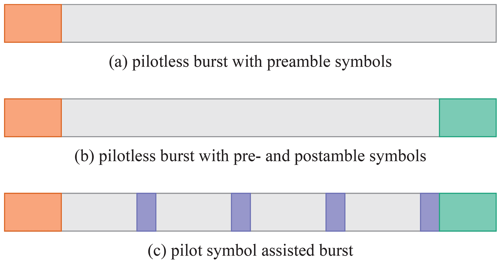
Figure 1DVB-RCS2 burst formats with preamble symbols in red, pilot symbols in blue, postamble symbols in green and payload symbols without color.
The tolerable burst frequency offset is not defined by the DVB-RCS2 standard but limited in agreement with gateway manufacturers. A representative set of values is in range from 0.5 % to 3 % of a symbol rate, which is specified by JTC (2014). A frequency offset of 3 % is possible to occur in high speed trains due to the Doppler effect.
To synchronize the received bursts there are different types of algorithms applied which can be classified into two categories, i.e. Data-Aided (DA) and Non-Data-Aided (NDA). Only known symbols, as introduced in Fig. 1, are used by DA synchronizers to estimate phase offset and frequency offset. With high number of known symbols it is possible to reach theoretical estimation bounds at very low Signal-to-Noise Ratio (SNR). However, the limited number of known symbols in the DVB-RCS2 standard are reduced as much as possible to generate a high spectral efficiency. In such cases NDA synchronizers may be preferred which consider all symbols of the burst for offset estimations. However this approach introduces self noise by the modulation removal. This may lead to poor performance at low SNR.
1.1 State-of-the-Art
Rife and Boorstyn (1974) (R&B) defined a state-of-the-art algorithm for frequency estimation that uses the Discrete Fourier Transformation, which is generally implemented by the so called Fast Fourier Transformation (FFT). An inherit limitation for the quality of frequency estimation is given by the FFT point size, which directly corresponds to the resolution of the frequency estimation. To counteract this limitation, the number of FFT points must be increased, typically between 4 to 16 times the length of the burst. Thus, improvement in accuracy is paid by increased hardware resources and reduced throughput, which is proportional to the FFT point size. Thus, from an implementation efficiency perspective it is desirable to keep the ratio of FFT length to burst length as small as possible.
Instead of adding further FFT points we investigate techniques for interpolation of the FFT result to improve the estimated frequency offset. We compare results of the standard approach of zero-padding against two advanced interpolation techniques, cf. Ali et al. (2014a). First, the interpolation offset is derived by a parabolic function utilizing the magnitude of the complex FFT output values. Second, for the energy interpolation the complex FFT output values are squared and therefore, the energy of the transforms, used for the interpolation. To the best of our knowledge this is the first comprehensive investigation of various interpolation techniques in the context of carrier synchronization with respect to communication performance and implementation efficiency.
1.2 New Contributions
In detail, this paper makes the following main contributions:
-
We show the trade-off between communication performance and implementation efficiency for three FFT-based carrier synchronization methods with interpolation. The communication performance is measured by the Frame Error Rate (FER) of channel decoding after carrier synchronization. Implementation efficiency is measured in terms of hardware resources and achievable throughput on a Xilinx Kintex FPGA.
-
Due to variation of number, amount and distribution of known symbols, different methods for carrier synchronization are required. A broad range of burst types is specified by the DVB-RCS2 standard including targeted communication performance. Two different interpolation techniques are investigated with NDA and two DA carrier synchronization schemes to efficiently achieve the targeted values.
The rest of the paper is organized as follows: In Sect. 2, we introduce the signal model, analyze the well known algorithms and describe the interpolation techniques formally. Section 3 shows the used simulation model and analyzes its communication performance. The hardware architecture and the implementation results are presented and discussed in Sect. 4. The paper is finally concluded in Sect. 5.
In this section we describe the signal model and introduce the used DA and NDA carrier synchronization methods. Finally, the interpolation techniques are described in detail.
2.1 Signal Model
The transmitted symbols s(l) with are sent to a receiver over a non-perfect channel. Hereby, L represents the number of modulated symbols of a burst. The Channel noise n(l) behavior is considered to be Additive White Gaussian Noise (AWGN). An evenly distributed frequency offset fo and phase offset ϕ is induced during transmission. They are assumed to be constant during the transmission of one burst but vary between different bursts. Gain control, timing synchronization and frame detection are not in the focus of this paper and, therefore, are considered to be carried out properly. In the complex baseband, the received sample sequence r(l) can be expressed as
The goal of carrier synchronization is to estimate the frequency offset and phase offset to correct the received sample sequence r(l).
2.2 Synchronization Methods
Carrier synchronization algorithms are partitioned in three categories, cf. Morelli and Mengali (1998). First, least-square-based algorithms, which perform inaccurate synchronization for low SNR regions and therefore are not discussed in this paper. Second, auto-correlation-based algorithms, which improve on the issue of the first class. Though, they suffer at the utilization of all known symbols with variable spacing. To overcome this issue, as third category, FFT-based algorithms are used for DVB-RCS2 carrier synchronization.
This paper focuses on the FFT-based algorithm introduced by Rife and Boorstyn (1974). Its wide estimation range and excellent estimation accuracy performance at low SNR qualify this algorithm for DVB-RCS2 synchronization. The problem of utilization of a consecutive sequence is solved by the modified R&B by Ali et al. (2014a) to support all known symbols with variable spacing and, alternatively, only pilot symbols. Additionally, the NDA method is explained.
Furthermore, the communication performance is improved with two interpolation techniques. Considering the squares of the magnitudes of the maximum amplitude and their neighbor bins or alternatively considering the magnitude of the named bins.
2.2.1 Data-Aided with all known symbols
The Data-Aided with all known symbols (DA-KS) method of the modified R&B is tailored to synchronize two types of burst type formats: first, bursts with large pilot period and, second, bursts with short pilot period and a limited number of pilot symbols. Here, the effect of phase ambiguity between two succeeding pilot blocks is removed. This is effective due to utilizing preamble and postamble symbols additionally to all pilot symbols for frequency and phase offset estimation.
For modulation removal on the received signal, data symbols of the received burst are wiped out and the known symbols are multiplied by their conjugate complex value . The modulation removed data sequence z(l) with is described as
The data sequence z(l) is extended with zeros at the end by N−L elements to form a data sequence x(k), where N is the FFT point size. The ratio of FFT point size N to burst length L is defined as zero-padding factor, an accuracy factor of four or higher is commonly used. The FFT values X(k) are derived by
which is called the spectral view of the data sequence. By spectral analysis, the position kf of the FFT output values which contains the highest amplitude is found as
Each index (also called bin) k of the FFT output X(k) represent a frequency range. Frequency offset and phase offset can be determined with the bin with maximum amplitude. They can be estimated by
and
The received burst is corrected with the concurrently estimated offsets as
To increase the accuracy of the estimated frequency offset and estimated phase offset the FFT point size N needs to be increased.
2.2.2 Data-Aided with pilot symbols only
For burst type formats with short pilot spacing and sufficiently large number of pilot symbols the algorithm of the previous section can be adapted to reduce the FFT point size. The here introduced method utilizes pilot symbols, i.e. Data-Aided with pilot symbols only (DA-PL). The modulation removal of Eq. (2) is restricted to pilot symbols. Let rp(l) be the sequence of received pilot symbols with LP elements. The spacing of pilot symbols is denoted by P.
The modulation removal is given by
with . The result is zero-padded with LP≤N to match x(k), the FFT applied as shown in Eq. (3) and the spectrum analyzed as in Eq. (4). The estimation of the frequency offset, as well as, the phase offset need to be adapted with respect to pilot spacing and the number of symbols before the first pilot S as
and
Finally, the input burst is corrected as shown in Eq. (7).
2.2.3 NDA Synchronization
For the NDA carrier synchronization, the described algorithm of Sect. 2.2.1 is adapted, cf. Ali et al. (2014b). The modulation index M, e.g., M=4 for QPSK, is required to remove the effect of the modulation.
The resulting data sequence z(l) is zero-padded to the FFT point size N. The FFT is applied and the spectrum analyzed as introduced in Eqs. (3) and (4), respectively. By considering the modulation index additionally to the previously known algorithm the frequency offset is estimated as
On the estimation of the phase offset at first the modulation index is considered as well.
The resulting phase is limited to a range from to and a M-times phase ambiguity is given as
with . To resolve this phase ambiguity, first, the input burst is corrected as shown in Eq. (7) and, second, a correlation of the corrected burst symbol sequence with a limited number of known symbols must be performed.
2.3 Interpolation Techniques
One way to improve estimated frequency offset and estimated phase offset is called zero-padding. By this the modulation removed symbol sequence z(l) is extended by a variable number of zeros to match the FFT point size. This is a common approach introduced by Rife and Boorstyn (1974).
Interpolation techniques are introduced to reduce the FFT point size and, thus, reducing complexity and increasing throughput. We compare two techniques to interpolate between the bin with maximum FFT output amplitude and its direct neighbors by using the magnitude or square magnitude of the complex FFT output.
2.3.1 Magnitude Interpolation
Due to the discrete nature of FFT each output bin represents a frequency range and Eq. (4) corresponds the middle of this frequency range. To improve this inaccurate frequency value interpolation techniques can be applied, e.g., as introduced by Zakharov et al. (2001) with a parabolic interpolation. With this, frequency and phase offset estimation results are improved.
The FFT output with index kf resulting from Eq. (4) including its left neighboring bin kl and right neighboring bin kr are considered for this approximation. The magnitudes are used to derive the approximation value Δ by the parabolic function with
Due to the construction of the interpolation approach the improvement is within the range of half a bin which means .
For correction of the frequency offset a virtual bin is generated with
This is used in Eqs. (5), (9) and (12) replacing kf.
The phase offset estimation is not considered by Zakharov et al. (2001). Therefore, we introduce a novel approach as for the energy interpolation defined by Ali et al. (2014a). A linear interpolation between the phase of FFT-output with index kf and the phase of a FFT-output of a neighboring bin is applied. The phases, ϕf, ϕl respectively ϕr, corresponding to the bins kf, kl and kr, respectively, are derived as shown in Eq. (6). A linear interpolation is calculated between these phases
to determine the phase offset of the virtual frequency offset bin.
2.3.2 Energy Interpolation
An alternative approach is an interpolation based on the energy of the complex FFT output bins which is introduced by Ali et al. (2014a). Therefore, the energy of each FFT bin is defined by
This approach avoids the complicated magnitude calculation of complex numbers. As in the previous section basically the same parabolic function, cf. Eq. (15), is used to approximate the offset from the bin position with the maximum value
The corresponding is calculated as shown in Eq. (16).
For the phase offset estimation, using this interpolation technique, a virtual FFT-output is calculated by
The phase of this resulting virtual FFT-output is used in Eqs. (6), (10) and (13) instead of X(kf) to achieve a more precise phase offset estimation.
This section presents the simulation model and gives an overview of the DVB-RCS2 burst types with linear modulation and their communication performance.
The DVB-RCS2 receiver is explored in the presence of frequency and phase offsets through extensive Monte Carlo simulations. Depending on the burst type, different DA and NDA carrier synchronization methods are feasible. An overview with focus on the achievable FFT point size reduction by adding the interpolation techniques is shown in this chapter.
3.1 Simulation Model
The simulation model considered in this paper is shown in Fig. 2. On the transmitter side, the information bits are encoded by a 16-state duo-binary TC encoder. The encoded binary sequence is mapped to symbols with respect to one of the following specified modulation schemes: BPSK, QPSK, 8-PSK or 16-QAM. The burst is constructed by adding known symbols according to a specified position. The resulting burst symbols are transmitted over an AWGN channel. In addition to channel noise, random phase offset ϕ and frequency offset fo are also injected to model carrier offset. On the receiver side, a carrier synchronization is performed on the erroneous symbols to derive an estimated phase offset and frequency offset for correcting the received burst accordingly. The known symbols are removed and the demapper determines under consideration of the modulation scheme a log likelihood ratio value for every bit of the remaining data symbols, which form the input of the TC decoder. Finally, the TC decoder gives an estimation of transmitted information bits.
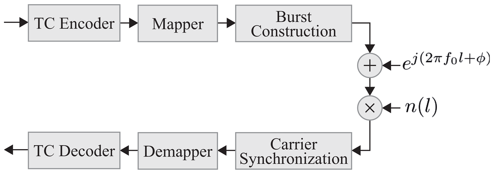
This paper assumes a uniformly distributed frequency offset up to 1.5 % of the symbol rate. For bit-precise simulation of the carrier synchronization the real and imaginary part of the received symbols are simulated with 8 bits input width.
To achieve the communication performance specified by JTC (2014), the 16-state duo-binary TC decoder is configured with the following parameters:
-
Max-Log-Map algorithm with 0.75 value of extrinsic scaling factor
-
8 iterations
-
6 bits quantization for the input Logarithmic Likelihood Ratio
-
The polynomials, interleaver parameter and puncturing pattern according to DVB-RCS2 standard
For this paper we considered 40 different burst types for linear modulation bursts, specified in the DVB-RCS2 standard, cf. JTC (2020a). Each of these burst types can be simulated using up to three different synchronization methods as well as pure zero padding and with either interpolation technique. In addition, several FFT point sizes are simulated for floating-point and for bit-precise model behavior. For an extensive overview, in this paper, approximately 3600 simulations were performed.
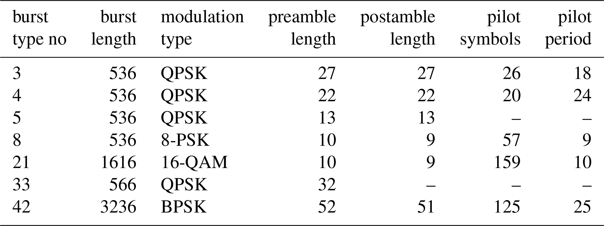
We present a representative subset of use cases in this paper. The introduced burst types, which differ in terms of their length, code rate, modulation type, number and distribution of known symbols, are shown in Table 1.
3.2 Frame Error Rates
We demonstrate and compare the impact of the in Sect. 2 introduced synchronization methods and interpolation techniques on the FER performance of TC decoder. We use zero-padding to improve the communication performance for the FFT-based synchronization methods as first approach. Additionally, we exploit interpolation techniques to keep the zero-padding factor minimum while achieving the desired communication performance.
As reference, for each demonstrated burst type, we show the results of the simulation chain, see Fig. 2, without phase and frequency offset as well as carrier synchronization. This baseline shows the best case communication performance of pure TC decoding or exact estimation of phase and frequency offset by a magic genie. Floating-point simulation are not shown to achieve better visibility in the plots. Furthermore, the bit-precise results have negligible difference in communication performance.
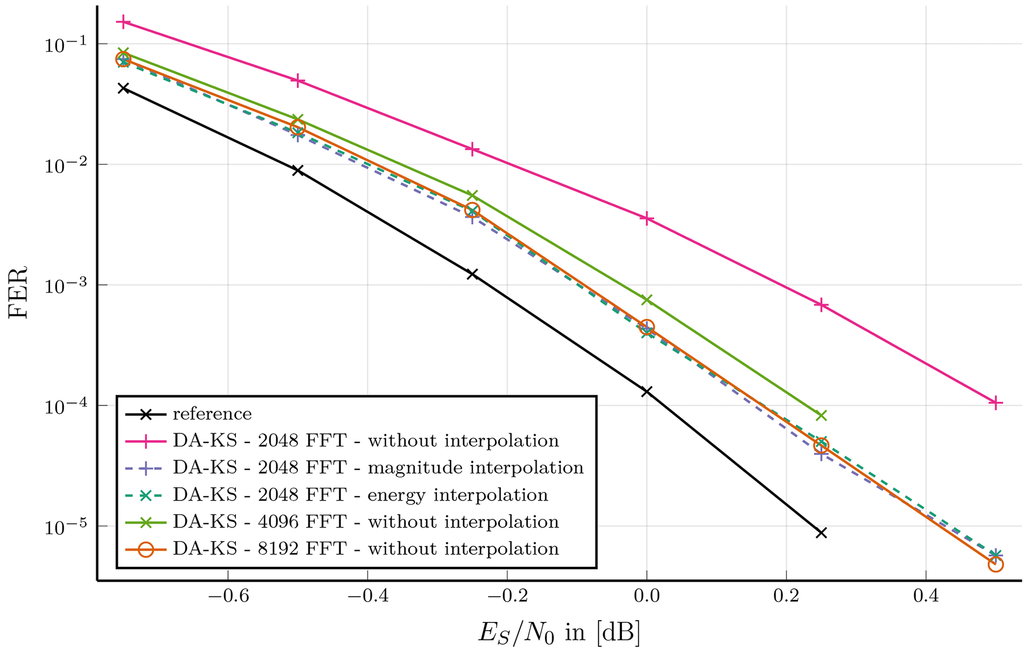
Figure 3Burst type 3: Preamble, pilotsymbols and postamble assisted burst format; DA-KS synchronization for a short burst length without interpolation and with two interpolation techniques compared with different number of FFT points.
The benefit of using interpolation techniques for the phase and frequency offset estimation is shown in Fig. 3. This is exemplified on burst type 3 (see Table 1), which is a short burst with QPSK Modulation scheme. This burst type contains 80 known symbols of which only 26 represent pilot symbols. Therefore, synchronization with the DA-KS method is applied as the SNR is too low for the NDA method. DA-PL synchronization is not suitable due to low number of pilot symbols. The results show a required number of FFT points of roughly 16 times the number of symbols for a carrier synchronization without interpolation. A lower number of FFT points would result into a poor error correction performance of the synchronization which is demonstrated with an FFT point size of 2048 and 4096. A further increase of the FFT size does not improve the FER performance at a given SNR point. By application of either interpolation technique the number of FFT points can be reduced from 8096 to 2048 without a loss in error correction performance.
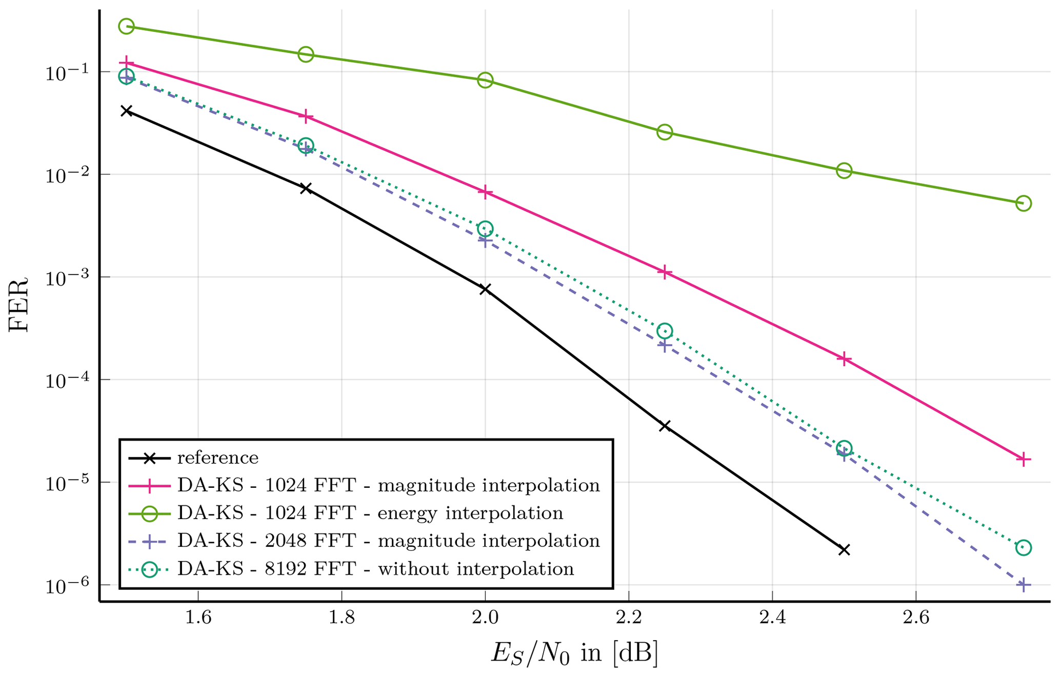
Figure 4Burst type 4: Preamble, pilotsymbols and postamble assisted burst format; DA-KS synchronization for a short burst length with two interpolation techniques compared at 1024 and 2048 FFT points.
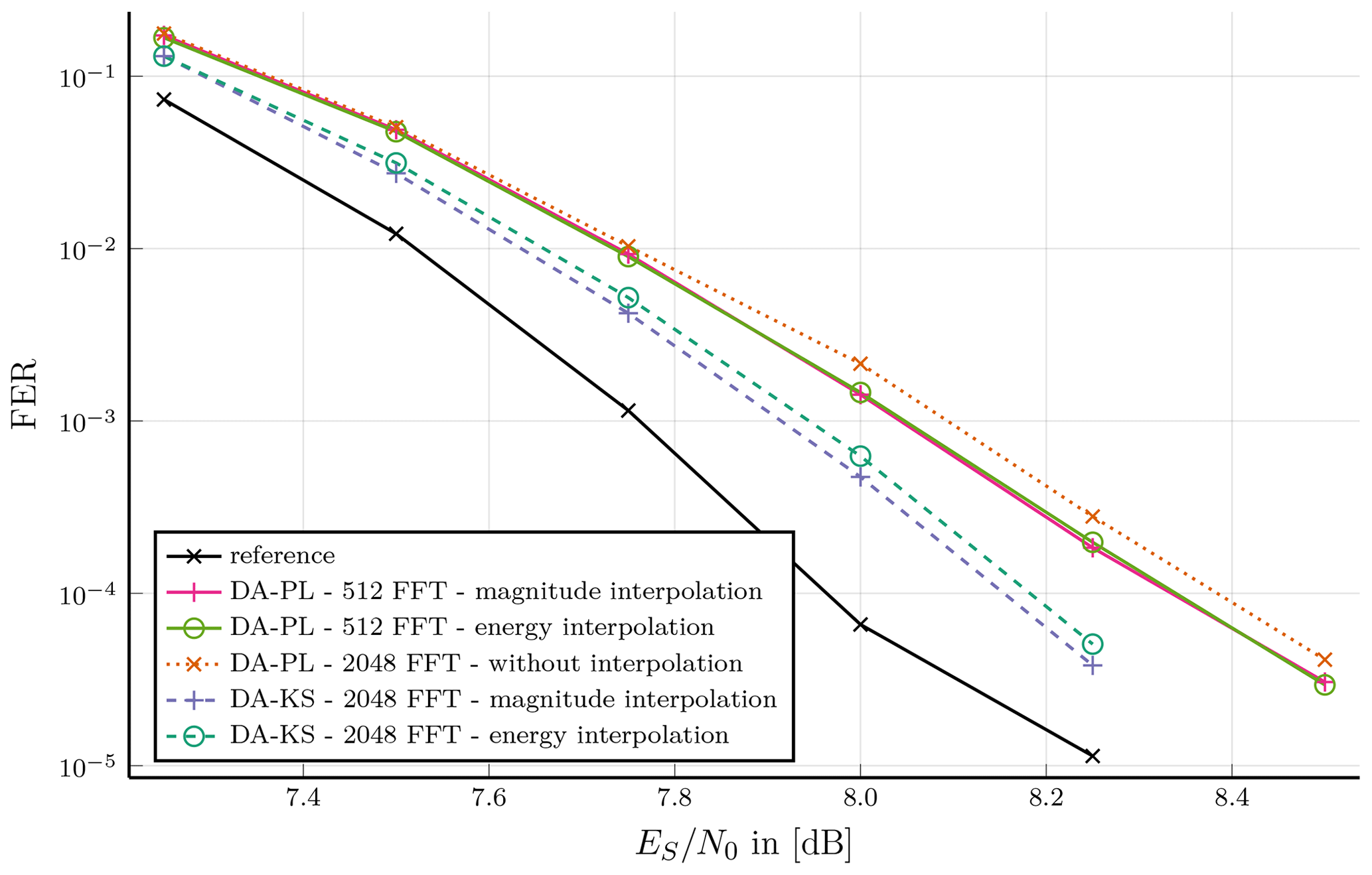
Figure 5Burst type 8: Preamble, pilot symbols and postamble assisted burst format; Performance of DA-KS vs. DA-PL synchronization at short burst length with two interpolation techniques.
Comparing both interpolation techniques shows for a few cases an impact on the communication performance as demonstrated in Fig. 4. Therefore, we consider burst type 4 with 536 symbols which has, similar to the previous burst type, long pre- and postamble and an increased pilot period. A 1024-point FFT supported by magnitude interpolation results into a tolerable synchronization performance. This is a very low zero-padding factor of about 1.9. Further increase of FFT point size by the factor two leads to a gain of about 0.1 dB at an FER of 10−3 and about 0.2 dB at 10−5. While the energy interpolation supported synchronization has almost identical behavior at this FFT point size, operation with 1024-point FFT results in poor communication performance.
Burst type 8 provides 57 pilot symbols, which is much higher than in the previous burst types. Therefore, the DA-PL synchronization method and the DA-KS method are investigated. By an FFT point less than the number of symbols, i.e. 512 points, a sufficient performance with DA-PL method supported by interpolation can be achieved. Without interpolation an equivalent communication performance is achieved with 2048 points. Further small FER improvement can be achieved Using the DA-KS method with interpolation and the same FFT point size, at an FER of 10−4, improvement of about 0.2 dB can be shown. An increased implementation complexity and decreased throughput is to be considered.
Burst type 21 is selected to demonstrate the effect of interpolation techniques on a medium length burst of 1616 symbols with 157 pilot symbols and and 16-QAM modulation in Fig. 6. Many pilot symbols and high SNR allow to employ DA-PL synchronization method. A 2048-point FFT without interpolation suffers poor error correction performance. With the energy interpolation method and an FFT point size reduction to 512 an improved performance is achieved at FER 10−3 of 0.15 dB to the reference simulation. Magnitude outperforms this by another 0.1 dB at the same FER point.
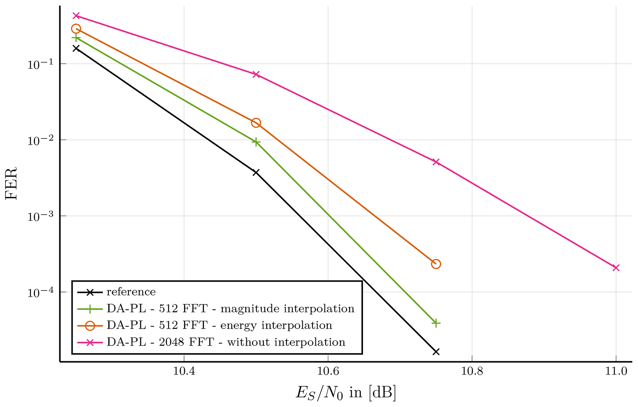
Figure 6Burst type 21: Preamble, pilot symbol and postamble assisted burst format; Communication performance of 16-QAM modulated, medium length burst with DA-PL synchronization at 2048 FFT size without interpolation and 512 with interpolation.
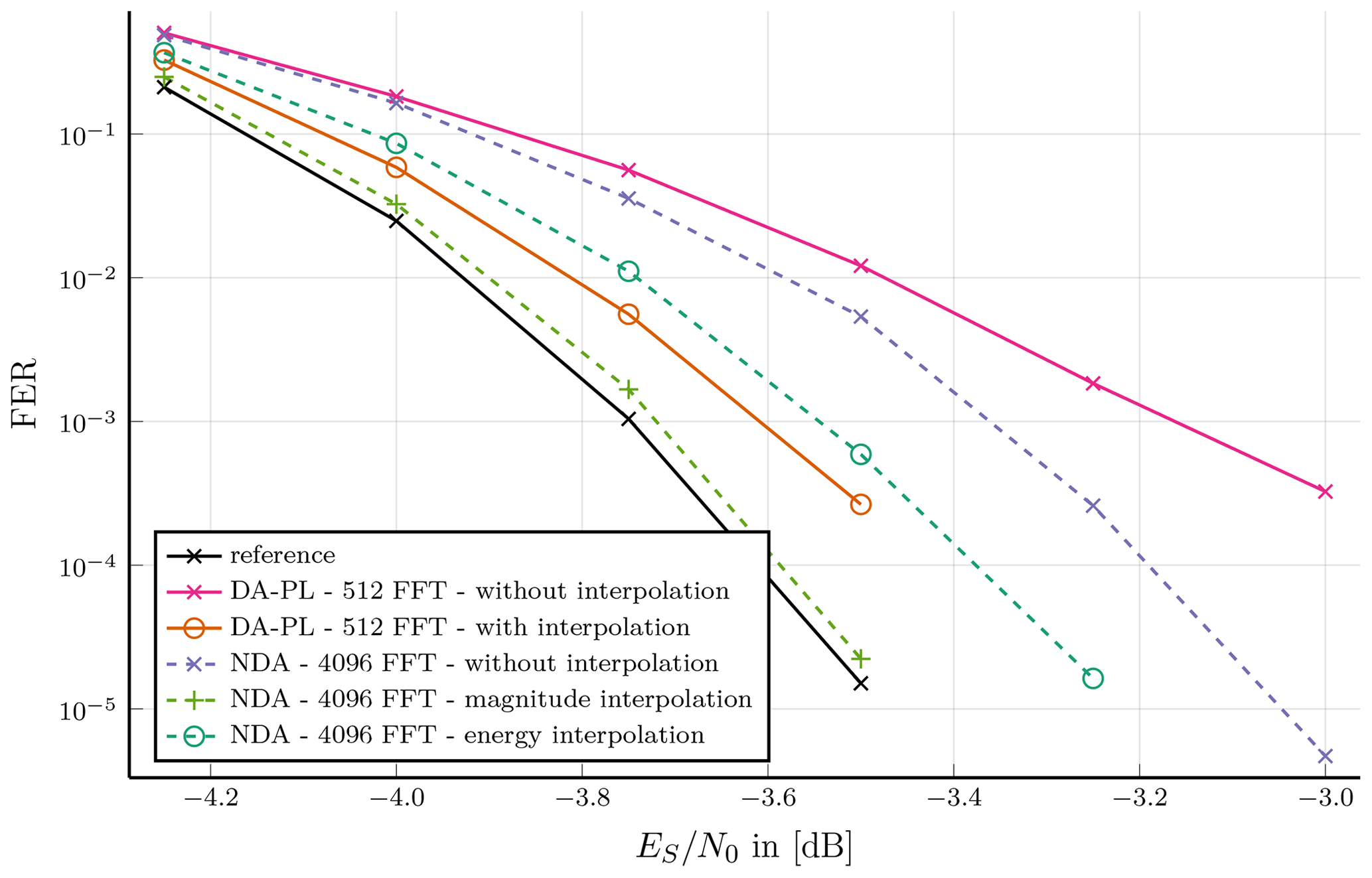
Figure 7Burst type 42: Preamble, pilotsymbols and postamble assisted burst format; BPSK modulated, very long burst with 512 FFT points at DA-PL synchronization and 4096 FFT points at NDA synchronization; Compared without interpolation and two interpolation techniques.
For long bursts types, exemplified on burst type 42, carrier synchronization performance shows the same characteristics of the interpolation as shorter burst types, solely a higher FFT point size is required for sufficient communication performance. In Fig. 7 this is shown where the DA-PL technique with interpolation reaches the reference communication performance at 10−3 to a gap of almost 0.1 dB and at 10−5 almost 0.2 dB. This is independent of the interpolation technique, while no interpolation at all performs poor. Note that DA-PL carrier synchronization method can only be applied if the maximum frequency offset is small enough that the phase difference between pilot symbols is unambiguous. Assuming 3 % frequency offset NDA synchronization becomes necessary. In this case a significant difference in communication performance of both interpolation techniques can be shown. While magnitude interpolation aligns to the reference curve, the energy interpolation performs slightly worse than the DA-PL synchronization methods with interpolation. Furthermore, this shows that a system with 4096-point FFT can be implemented, which can process all burst types introduced in the DVB-RCS2 standard.
In contrast to the previous burst types, burst type 5 has a short pre-/postamble period and no pilot symbols and, thus, is not suitable to be synchronized with neither DA-KS nor DA-PL technique. Application of the NDA synchronization leads to results shown in Fig. 8. At least a 1024-point FFT is required. Magnitude interpolation technique FER is very close to reference FER. The energy interpolation technique is about 0.1 dB worse. Without interpolation requires a doubling of point size.
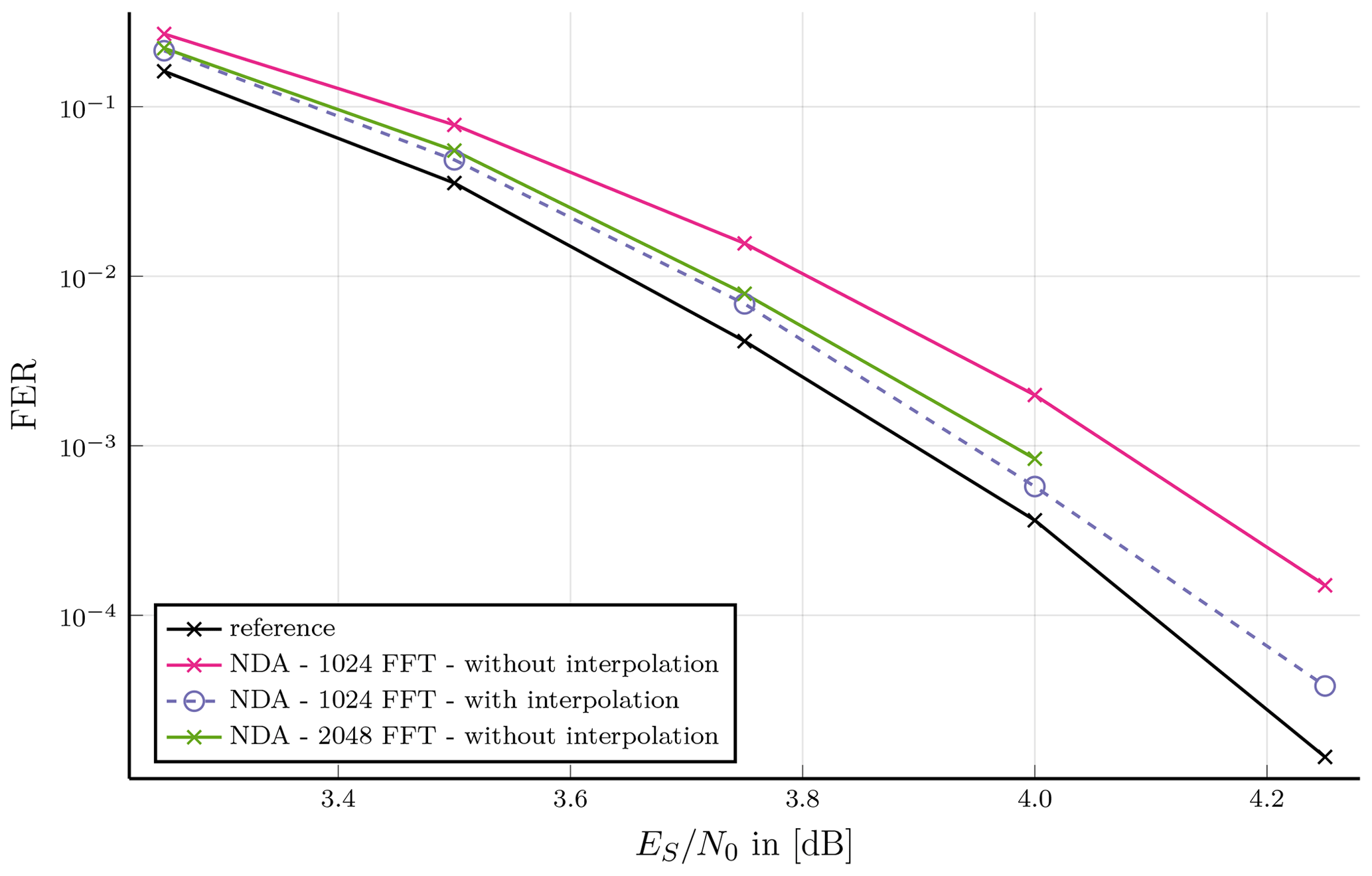
Figure 8Burst type 5: Preamble and postamble assisted burst format; NDA synchronized burst type without interpolation compared to two interpolation techniques with a fixed FFT point size.
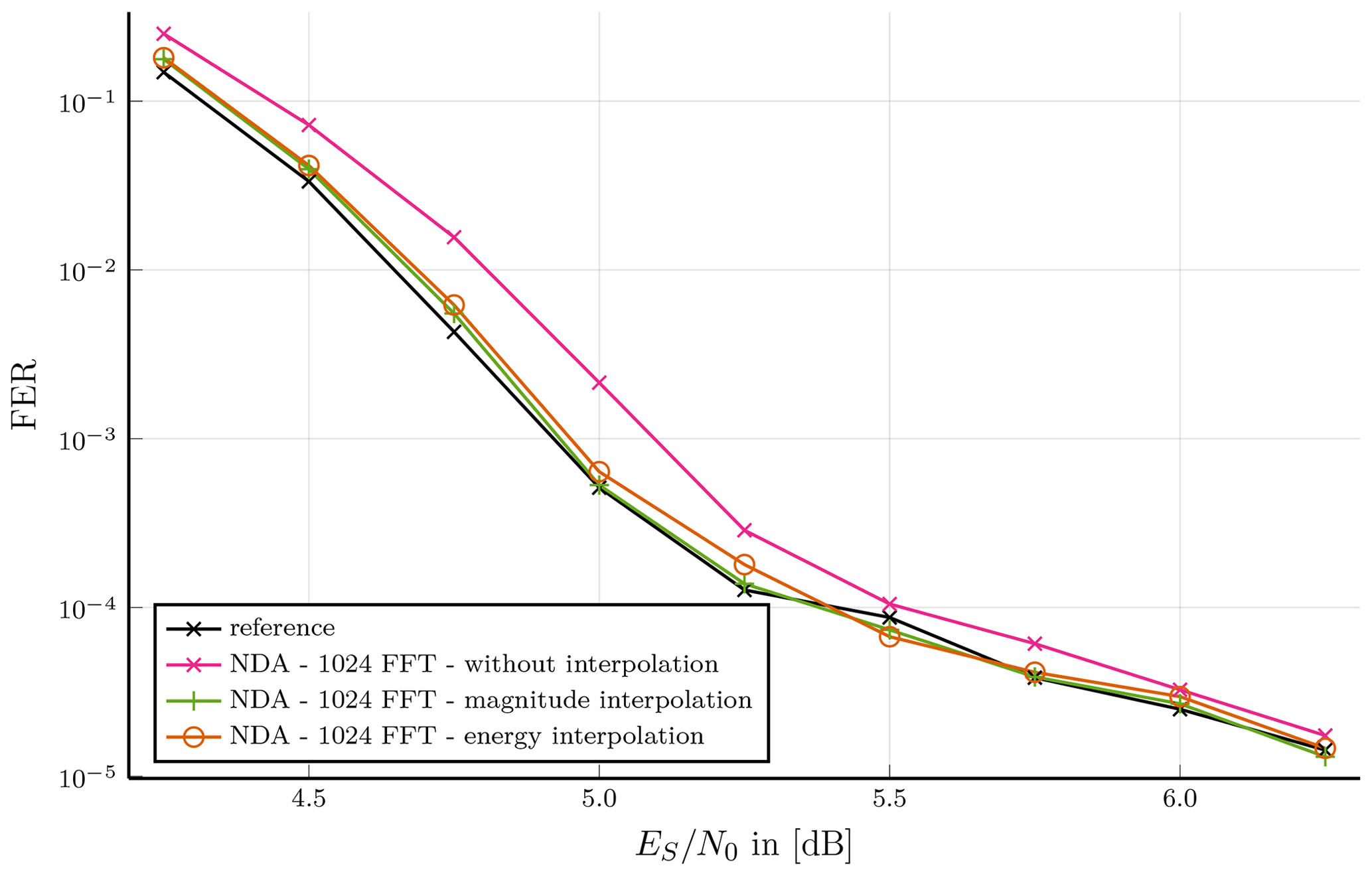
Figure 9Burst type 33: Preamble assisted burst format; NDA synchronization of short burst length without interpolation and with two interpolation techniques.
Figure 9 shows NDA synchronization of burst type 33 without and with either interpolation techniques compared with 1024-point FFT. The burst type contains only preamble with 32 symbols and thus is not sufficient to synchronize using DA methods. Both interpolation techniques almost overlap with the reference simulation. The synchronization without interpolation is at an FER of 10−3 with less than 0.2 dB performing close to the reference plot. An increase of the FFT point size to 2048 results in an equivalent performance as the interpolated plots. This shows that an FFT-based synchronization method needs not always to be interpolated; in order to increase throughput a small communication performance loss can be accepted.
In this selection of exemplary results we were able to show communication performance for different lengths, modulation types and distribution of known symbols on various burst types defined in Table 1. Objective is to achieve communication performance close to the TC decoder reference simulations. Furthermore, the decrease of FFT points by application of interpolation techniques of up to a factor of four was shown. In most cases there was no significant difference between either interpolation technique, especially for a higher number of FFT points. With a very low zero-padding factor at a few burst types the magnitude interpolation outperformed the energy interpolation regarding communication performance.
In this section, we present hardware implementation results of our carrier synchronization with the investigated interpolation techniques. Each of these architectures is synthesized for different FFT point sizes, which we compare at fixed communication performance based on the resulting hardware complexity.
4.1 Architectures
In order to compare hardware implementation efficiency, i.e. resources and throughput, our designs were implemented in synthesizable VHDL that is mapped onto a Xilinx Kintex FPGA. To optimize the implementation we use Xilinx highly optimized Intellectual Property (IP) cores. For the FFT computation we selected the pipelined streaming I/O architecture of the Xilinx FFT IP core, cf. Xilinx (2017b). Furthermore, CORDIC IP cores are used for the computation of phases, see Eqs. (6), (13) and (17), and complex magnitudes, see Eq. (15), cf. Xilinx (2017a).
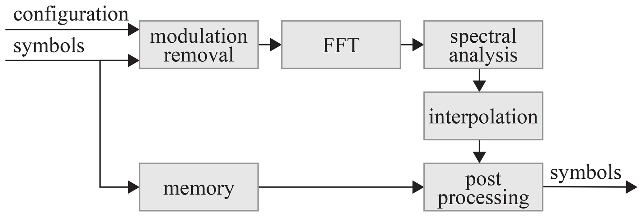
We have implemented three hardware architecture types that differ in the respective interpolation method. The block diagram of the general architecture is shown in Fig. 10. The configuration allows to switch the burst configuration and the synchronization method at run-time depending on the burst type. The sub-block modulation removal implements the DA methods, see Eqs. (2) and (8) as well as the NDA method, see Eq. (11), for modulation removal and feeds the FFT-block including zero-padding. This block is run-time configurable up to a maximum point size defined before synthesis. The output of the FFT-block is continuously processed in the spectral analysis block to find the bin corresponding to the estimated frequency offset, see Eq. (4). Furthermore, this sub-block comprises the division operation for the DA-PL and NDA synchronization methods as well as the phase calculations according to the burst type specific configured synchronization method. For the evaluation of the different interpolation techniques, the component interpolation was implemented for each technique separately. The reference design without interpolation directly passes values after spectral analysis to post processing. The sub-block post-processing receives the in memory stored burst symbols and results of the interpolation to correct frequency and phase offset. In addition, phase ambiguity is resolved in case of NDA synchronization and taken into account during phase offset correction.
The architecture, introduced in Fig. 10, is developed to synchronize the linear burst modulated burst types which are specified by the DVB-RCS2 standard. Furthermore, to show trade-offs between communication performance and implementation efficiency, we synthesized three different maximum FFT point sizes for each interpolation approach.
Table 2Post P&R Results of the Architecture of a DVB-RCS2 Carrier Synchronization Module.
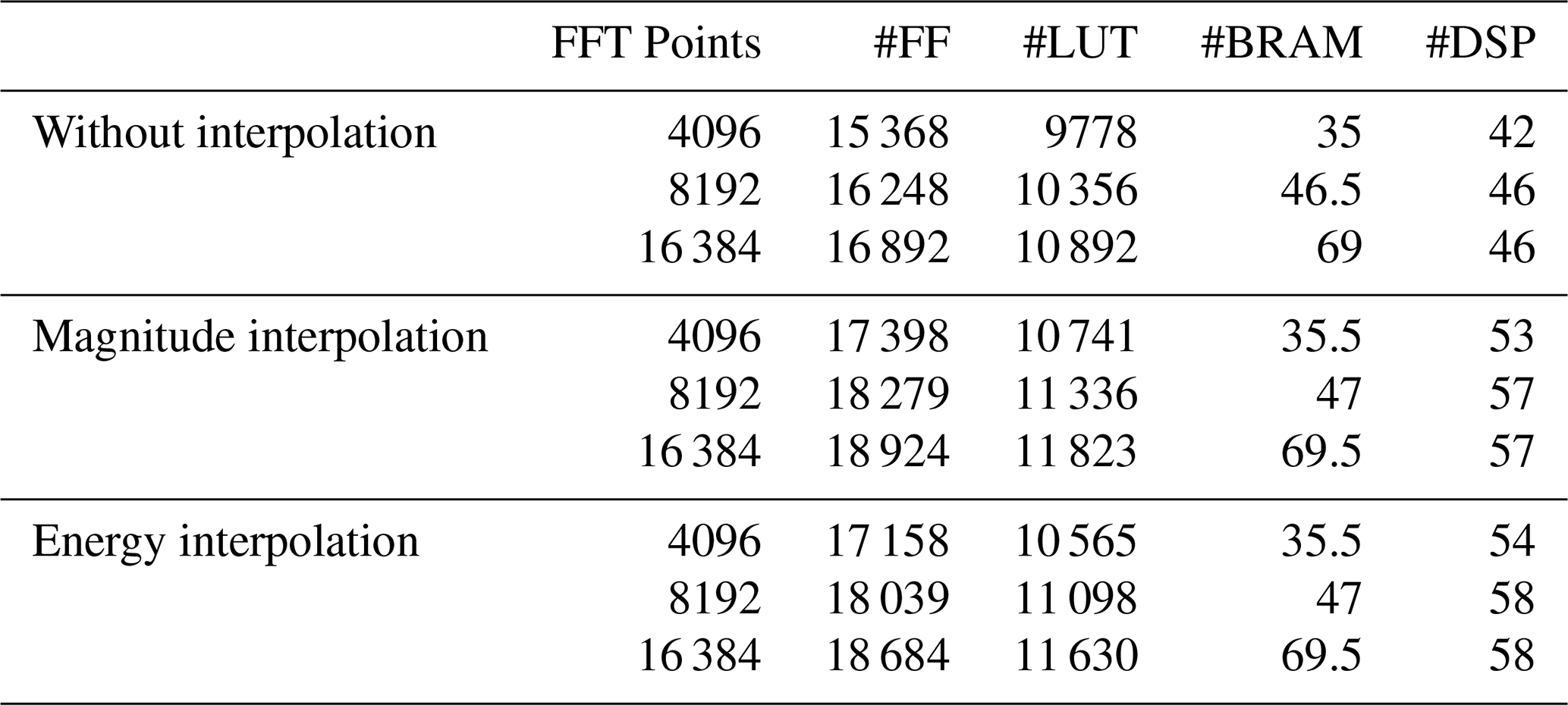
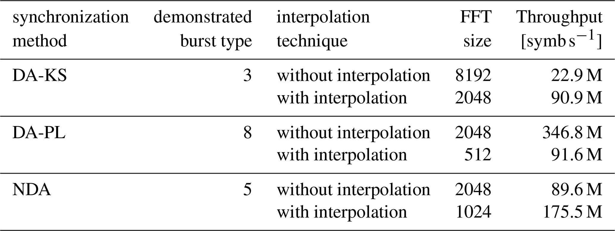
Table 3DVB-RCS2 carrier synchronization throughput comparison for different synchronization methods with and without interpolation.
4.2 Implementation Results and Analysis
We used Xilinx Vivado 2018.3 suite for synthesis and place and route (P&R). The target platform is Xilinx Kintex family with speedgrade −2. The input symbols for real and imaginary part utilize 8 bit, respectively. According to the defined burst types of the DVB-RCS2 standard, the maximum burst length was set to 4096 symbols. Post P&R we achieved about 350 MHz clock frequency for all designs.
The utilized FPGA resources consist of Flip-Flops (FF), Lookup Tables (LUT), Block Random Access Memories (BRAM) and Digital Signal Processing (DSP) units, as shown in Table 2. Different maximum FFT point numbers were implemented for pure zero-padding and the interpolation techniques presented in Sect. 2. Table 2 shows that the required resources after P&R for the respective interpolation method at different FFT point sizes differ slightly. A doubling of the FFT point size results in an additional utilization of about 500 to 1000 FFs, 500 LUTs and four DSP units, which corresponds to an increase of less than 10 % of each resource. Only the necessary BRAM resources increase by about 50 %.
The two compared interpolation techniques require about the same amount of all resources with a rather small difference of a few blocks. Compared to pure zero-padding, it is evident that for either of the two interpolation techniques additional blocks are utilized, i.e. about 2000 FFs, 1000 LUTs and 13 DSP units. This is due to the additional implementation effort of the parabolic interpolation, see Eqs. (15) and (19), respectively, and CORDIC operations, see Eq. (15).
To make a fair comparison, we fix the communication performance for all three approaches. In Table 3 the achieved throughput is shown. It is independent of the maximum number of FFT points, but dominated by the actual FFT point size. Furthermore, the achieved throughput is proportional to the number of burst symbols and frequency and inversely proportional to the utilized FFT point size. One burst type is selected for the demonstration of each synchronization method. For DA-KS the communication performance shown in Fig. 3 at 8192-point FFT without interpolation is compared to 2048-point FFT with either interpolation. The determined throughput depends on the number of burst symbols, eg. 536 symbols for burst type three, as shown in Table 1. The achieved frequency is 350 MHz, therefore, the resulting throughput is 22.9 M symb s−1 without interpolation and 90.9 M symb s−1 with either interpolation technique, shown in Table 3. For DA-PL synchronization method burst type 8 and for NDA synchronization method burst type 5 are compared with pure zero-padding against either interpolation, see Figs. 5 and 8, respectively.
Overall, the throughput of either interpolation technique is the same due to the same FFT size at fixed communication performance close to the reference communication performance. Furthermore, the required resources shown in Table 2 differ less than 3 %. The implementation efficiency is defined as throughput over resources. Thus, the resulting implementation efficiency of the two architectures is almost identical. But a large improvement can be shown for the comparison between pure zero-padding synchronization to adding either interpolation technique. There, the resources utilization is increased by less than 20 %. In contrast we can see that the throughput differs by factor of two to four. We conclude that either of the interpolation techniques leads to an increase of the implementation efficiency of at least 1.67 up to 3.33.
We have investigated the effect of two interpolation techniques on three different FFT-based carrier synchronization methods regarding communication performance and hardware implementation efficiency. For all three synchronization methods, we observed better communication performance at the same FFT point size by adding the interpolation techniques. In some cases characterized by a very low zero-padding factor, the magnitude interpolation technique showed better communication performance than the energy interpolation technique. To achieve the same communication performance as a standard synchronization method without interpolation, the interpolation-based techniques required half the FFT point size or less. Thus, using interpolation techniques leads to an improvement in throughput by a factor of two to four while the increase in hardware resources was upper bounded by less than 20 %. This leads to an improved hardware implementation efficiency at a fixed communication performance by at least 67 % by using interpolation.
The source code is represented by the formulas in this paper and can be reproduced. The applied source code is based on proprietary libraries, which are not publicly available.
All relevant models and results of the research are contained in the manuscript. The results can be reproduced with the presented formulas.
OG and UW contributed equally on the conceptualization, methodology, software, hardware, validation, formal analysis, investigation, writing, visualization, review and editing. NW contributed on the supervision, review and editing.
The authors declare that they have no conflict of interest.
Publisher's note: Copernicus Publications remains neutral with regard to jurisdictional claims in published maps and institutional affiliations.
This article is part of the special issue “Kleinheubacher Berichte 2020”.
This paper was edited by Jens Anders and reviewed by Daniel Krüger and one anonymous referee.
Ali, I., Wasenmuller, U., and Wehn, N.: Hardware implementation issues of carrier synchronization for pilot-symbol assisted bursts: A case study for DVB-RCS2, in: 2014, 8th International Conference on Signal Processing and Communication Systems, 15–17 December 2014, Gold Coast, QLD, Australia ICSPCS 2014 – Proceedings, Institute of Electrical and Electronics Engineers Inc., https://doi.org/10.1109/ICSPCS.2014.7021078, 2014a. a, b, c, d
Ali, I., Wasenmüller, U., and Wehn, N.: Feedforward carrier synchronization for pilotless bursts of DVB-RCS2, in: 2014 9th International Symposium on Communication Systems, Networks and Digital Signal Processing, CSNDSP 2014, Institute of Electrical and Electronics Engineers Inc., 342–347, https://doi.org/10.1109/CSNDSP.2014.6923851, 2014b. a
Douillard, C. and Berrou, C.: Turbo codes with rate- constituent convolutional codes, IEEE T. Commun., 53, 1630–1638, https://doi.org/10.1109/TCOMM.2005.857165, 2005. a
JTC: EN 301 545-2 – V1.1.1 – Digital Video Broadcasting (DVB), Second Generation DVB Interactive Satellite System (DVB-RCS2), Part 2: Lower Layers for Satellite standard, Tech. rep., ETSI, Sophia Antipolis Cedex, France, 2012. a
JTC: TR 101 545-4 – V1.1.1 – Digital Video Broadcasting (DVB), Second Generation DVB Interactive Satellite System (DVB-RCS2), Part 4: Guidelines for Implementation and Use of EN 301 545-2, Tech. rep., ETSI, Sophia Antipolis Cedex, France, 2014. a, b
JTC: EN 301 545-2 – V1.3.1 – Digital Video Broadcasting (DVB), Second Generation DVB Interactive Satellite System (DVB-RCS2), Part 2: Lower Layers for Satellite standard, Tech. rep., ETSI, Sophia Antipolis Cedex, France, 2020a. a, b
JTC: TS 101 545-1 – V1.3.1 – Digital Video Broadcasting (DVB), Second Generation DVB Interactive Satellite System (DVB-RCS2), Part 1: Overview and System Level specification, Tech. rep., ETSI, Sophia Antipolis Cedex, France, 2020b. a
Morelli, M. and Mengali, U.: Feedforward Frequency Estimation for PSK: A Tutorial Review, Eur. T. Telecommun., 9, 103–116, https://doi.org/10.1002/ett.4460090203, 1998. a
Rife, D. C. and Boorstyn, R. R.: Single-Tone Parameter Estimation from Discrete-Time Observations, IEEE T. Inform. Theory, 20, 591–598, https://doi.org/10.1109/TIT.1974.1055282, 1974. a, b, c
Xilinx: CORDIC v6.0 – LogiCORE IP Product Guide, Tech. rep., Xilinx, Inc., San Jose, CA, United States, available at: https://www.xilinx.com/support/documentation/ip_documentation/cordic/v6_0/pg105-cordic.pdf (last access: 1 February 2021), 2017a. a
Xilinx: Fast Fourier Transform v9.0 – LogiCORE IP Product Guide, Tech. rep., Xilinx, Inc., San Jose, CA, United States, available at: https://www.xilinx.com/support/documentation/ip_documentation/xfft/v9_0/pg109-xfft.pdf (last access: 1 February 2021), 2017b. a
Zakharov, Y. V., Baronkin, V. M., and Tozer, T. C.: DFT-based frequency estimators with narrow acquisition range, IEE P.-Commun., 148, 1–7, https://doi.org/10.1049/ip-com:20010060, 2001. a, b