 | 21 Mar 2023
Sequential Rotation of Antenna Array Elements – Rotation Angle for Optimum Array Polarization
The principle of sequential rotation, a well-known method to arrange the radiating elements of antenna arrays, is briefly described, and the impact on the polarization of different antenna array configurations is presented. The influence of the number of rotations and rotation angles is investigated, and arrangements for optimized polarization quality of antenna arrays are shown, which are of significant importance for current and future communications systems.
- Article
(2415 KB) - Full-text XML
- BibTeX
- EndNote


The principle of sequential rotation is an established method to arrange the radiating elements of antenna arrays. Though the design can become more complex compared to arrays without rotated elements, there are two main applications. The first one is to improve the AR (axial ratio) of CP (circular polarization). AR defines the quality of CP as magnitude ratio of a TEM (transverse electromagnetic) wave's two orthogonal and 90∘ phase shifted field vectors. Three cases are distinguished:
-
CP (Circular polarization): ,
-
EP (Elliptical polarization): ,
-
LP (Linear polarization): .
In antenna arrays intended for CP the single elements often exhibit only EP. This is e.g. due to manufacturing cost reduction or other design aspects. But the sequential rotation of such elements still may improve the array performance significantly (Pozar and Schaubert, 1995; Smith, 1991).
The second main application is the usage of sequentially rotated linearly polarized single elements to get a circularly polarized antenna array (Huang, 1986; Hall et al., 1989). This approach allows for a very simple antenna element design. If the phase relations between the elements are adjustable like e.g. for phased arrays or in systems for DBF (digital beam forming), both left-handed and right-handed CP can be realized.
In addition to the improved polarization quality, the principle of sequential rotation will also enhance the symmetry of antenna array radiation characteristics, as it introduces a sort of averaging for the potential asymmetrical single element radiation characteristic. Indeed, the only real drawbacks of this method are the potential excitation of grating lobes (Kuhlmann, 2013) and a more complex design, especially in highly integrated active antenna arrays like e.g. for satellite communication (Kuhlmann and Jacob, 2010) or current and future communications standards 5G and 6G.
The importance of sequential rotation in antenna arrays is further supported by more than 400 publications about the usage of this method, listed at IEEE Explore between 2010 and 2022. The applications, frequency ranges, and array sizes vary a lot, but, to the author's knowledge, no recent publication investigates the topic presented here. Usually the array elements are rotated by 90∘ on rectangular grids to e.g. improve polarization quality, sometimes by 180∘. The latter, as will be seen in the next section, might not have brought the desired result.
This paper investigates the fundamental building blocks of potentially large arrays. The questions it answers are:
-
What is theoretically the minimal required distribution of elements to achieve a perfect CP?
-
Which distributions do not improve the polarization quality but unnecessarily increase the design complexity?
As it would lead to too many combinations to investigate, this paper does not discuss:
-
Type of single element radiator (patch, horn,…),
-
Array type (linear, planar, spatial),
-
Grid (rectangular, triangular,…),
-
Element distance (determines grating lobes and scanning range).
Further information on these four topics as well as mutual coupling can be found in e.g. Kuhlmann and Jacob (2009) and Kuhlmann (2013). Here (Kuhlmann, 2021), only arrays consisting of perfect isotropic radiators are considered, and the AF (array factor) is calculated for the main direction. As is known from antenna theory, a simple multiplication of the AF with a simulated or measured antenna yields a complete radiation diagram. There is basically no limit to complexity. E.g. if the application requires two different polarized antenna arrays, either using the same grid (dual-polarized elements) or on different grids (Jaschke, 2021), the result is gained by superposition.
In Sect. 2 of this paper, the mathematical definitions for polarization calculations and some examples are given, in Sect. 3, several cases are studied, and in Sect. 4 some current and future applications are examined.
At first, some definitions are introduced. For a reference plane (here xy) which is orthogonal to the direction of radiation (here z) the four main polarizations have the following normalized field vectors:
This is valid for transmit antennas. For receive antennas the vectors for RCHP and LCHP must be exchanged (Pozar, 2005). For the principle of sequential rotation the elements are usually rotated by , N being the number of elements of the antenna array. E.g., for a two element array the rotation angle is 180∘, and for a four element array it is 90∘. Both cases are depicted in Fig. 1. Also shown is an imperfect AR for each element represented as two orthogonal arrows with unequal length.
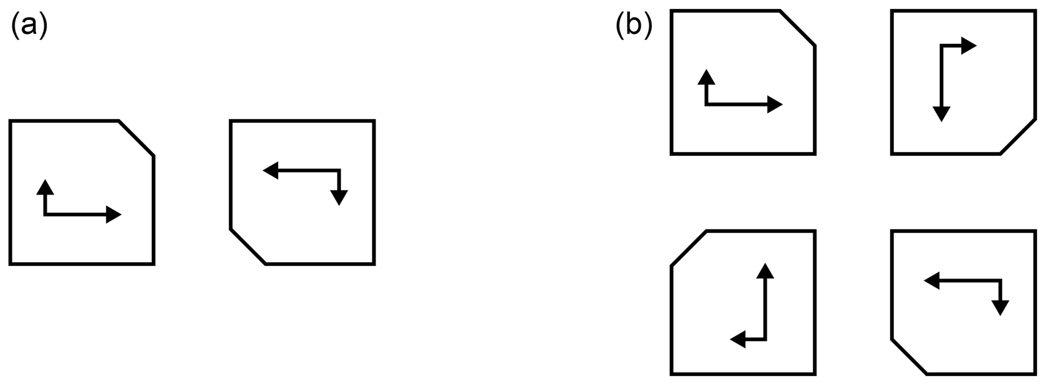
Figure 1Subgroups for antenna arrays with two (a) and four (b) sequentially rotated elements.
Large antenna arrays are usually assembled from several smaller sub arrays or subgroups, thus following a modular principle, which enables to adapt the array size to applications with different requirements. To get the AR of a subgroup, the vectorial AF must be calculated. In main direction of the array an electrical phase equal to the rotation angle of the element is added. A left-handed CP with AR =2 leads to (no normalization)
for a two element subgroup and to
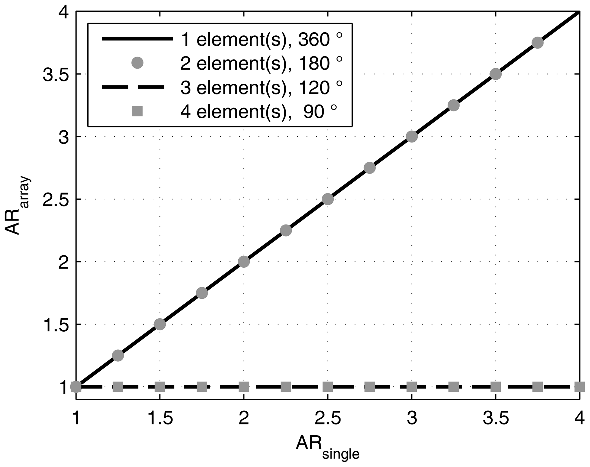
for a four element subgroup. As can be seen from Eq. (5), in any array with elements rotated by 180∘ the AR of the single antenna will not be improved. In Eq. (6) however, the AR is ideal. Indeed, this is true for any AR and any size of subgroup, as long as there are more than two elements, a rotation by , and the AR is identical for each element. This is examplarily depicted in Fig. 2 for N=1…4 elements and an AR of the single element between 1 and 4.
If for some reasons (manufacturing tolerance, element position, etc.) the AR is slightly different for each element, a nearly ideal CP is still achievable, as long as the AR differences are equally distributed for many elements. Even if the elements are linearly polarized (AR=∞), the polarization of the array is perfectly circular. Although depending on the element distance, cross-polarized grating lobes (e.g. right-handed CP instead of left-handed CP) might occur. This effect cannot be completely avoided, but it can be reduced by sequentially rotated subgroups (Hall and Smith, 1993, 1994; Thiel and Dreher, 2004) or by introducing random techniques (Smolders and Visser, 2014).
In Sect. 2 it has been shown, that the CP of a sequentially rotated antenna array is ideal for three or more elements per subgroup, and it is identical to the element's AR for one element or two elements per subgroup. In Fig. 3, the AR of a two element subgroup with different rotation angles is presented. For 0 and 180∘, the AR is not improved, while it is perfect (AR =1) for 90∘, even with only two elements. In between the AR changes gradually.
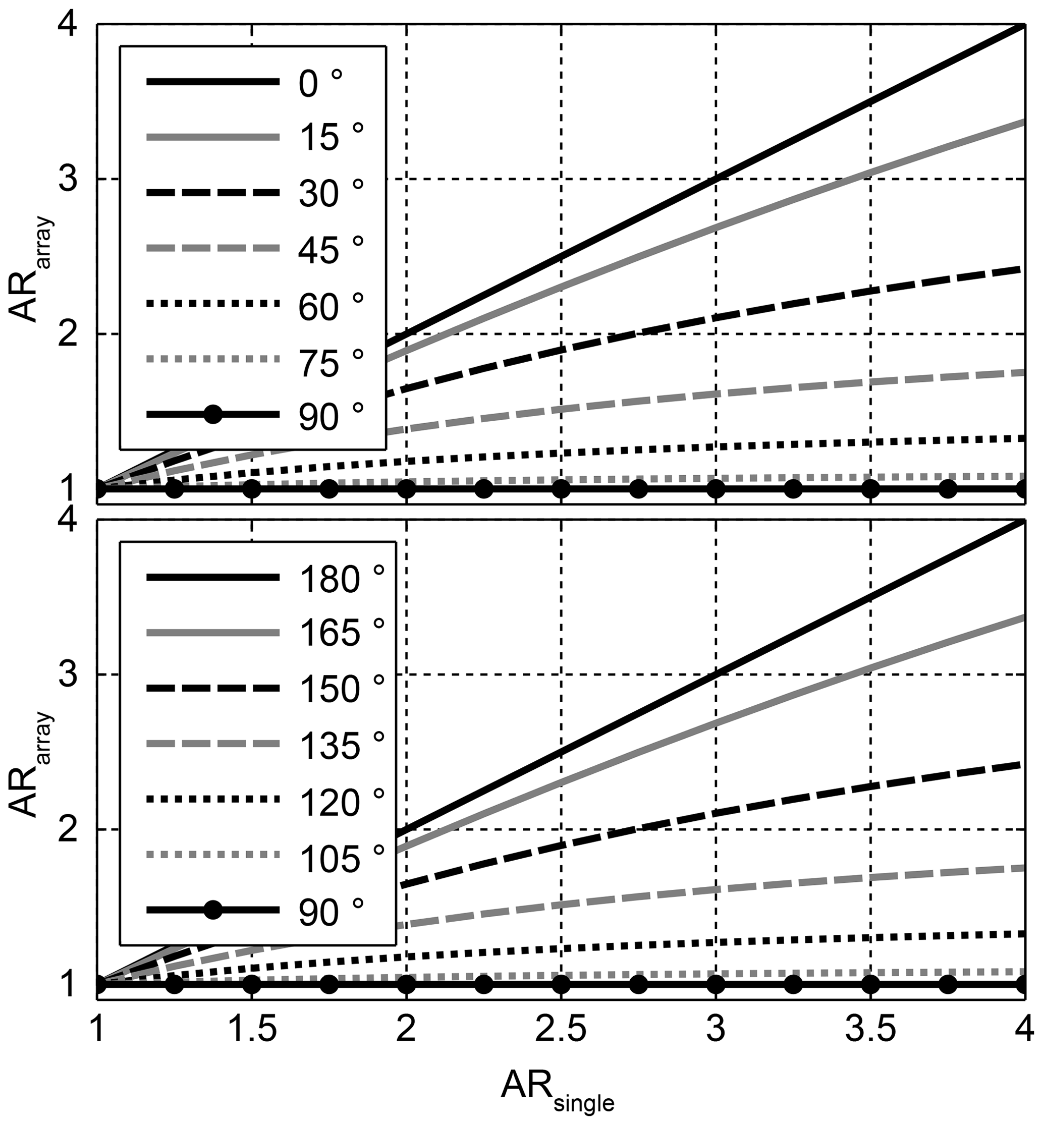
Figure 3AR for antenna arrays with two sequentially rotated elements vs. AR of single element.
Figure 4 shows the same study for a three element subgroup. For this case the polarization is perfectly circular for the angles 45, 60, 120, and 135∘. Just as for the two element subgroup, the range from 180 to 360∘ is a repetition of the range 0 to 180∘.
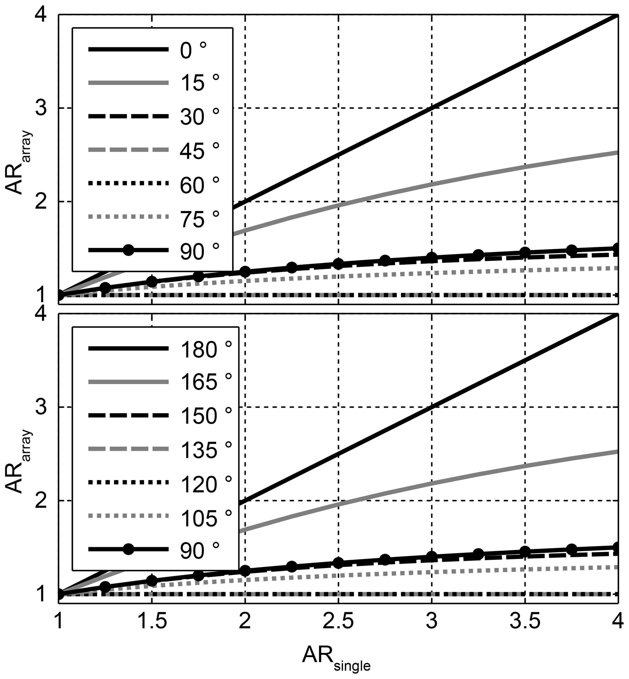
Figure 4AR for antenna arrays with three sequentially rotated elements vs. AR of single element.
To better investigate the rotation angle dependency itself, in Fig. 5 ARarray for the three element subgroup is plotted vs. the rotation angle instead of ARsingle. And in Fig. 6 the AR is plotted vs. the rotation angle for different subgroup sizes. For the rotation angle 180∘ (and 360∘) the AR of the array follows the AR of the single element. All other rotation angles improve the AR. The range from 180 to 360∘ is symmetrical to the range 0 to 180∘ with 180∘ being the mirror plane of symmetry. The number of rotation angles which achieve perfect CP increases with the number of subgroup elements. For an infinite number of elements, the AR is one for all rotations angles except for 0 and 180∘. Also, the AR is always one for an even number of subgroup elements and a rotation angle of 90∘.
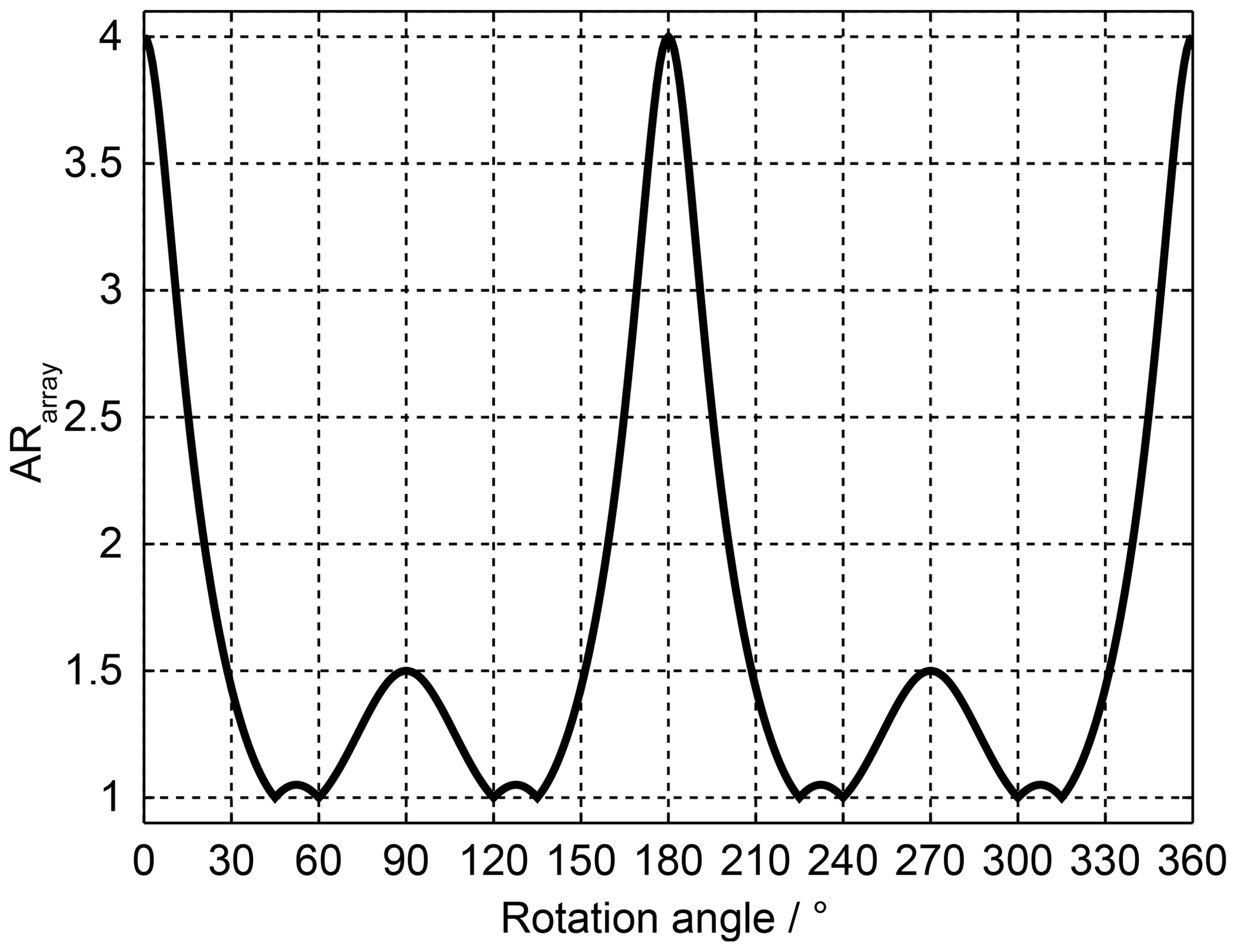
Figure 5AR for antenna arrays with three sequentially rotated elements vs. rotation angle, ARsingle=4.
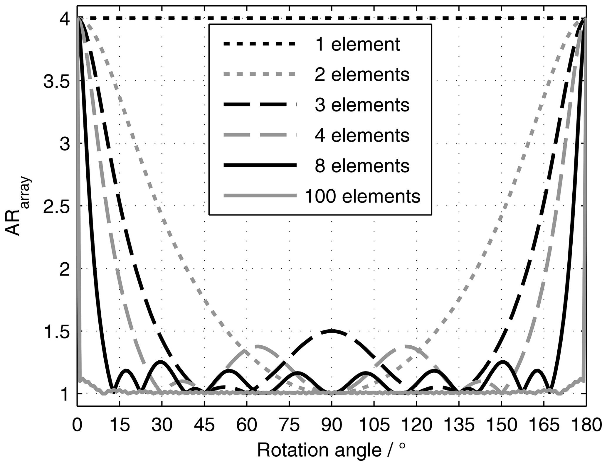
Figure 6AR for antenna arrays with sequentially rotated elements vs. rotation angle, ARsingle=4.
In the telecommunications standard 5G antenna arrays at microwave and millimeter wave frequencies are introduced and of high importance for success (5G Lab, 2016). Especially multiple beam capabilities for base stations will be essential to enable the required number of connections, the high bandwidth for each user, and the small latency (∼1 ms) in real time applications.
Apart from mobile phones, many smart devices like vehicles or buildings will be part of a large network (Internet of Things – IoT). For autonomous systems the connection stability is of outmost importance. Not all but many of these new applications are candidates for use of antenna arrays. While base station antenna arrays might be realized conventionally on rectangular grids, indoor antennas might utilize other shapes, e.g. triangular or circular grids (Airrays GmbH, 2016; see Fig. 7).
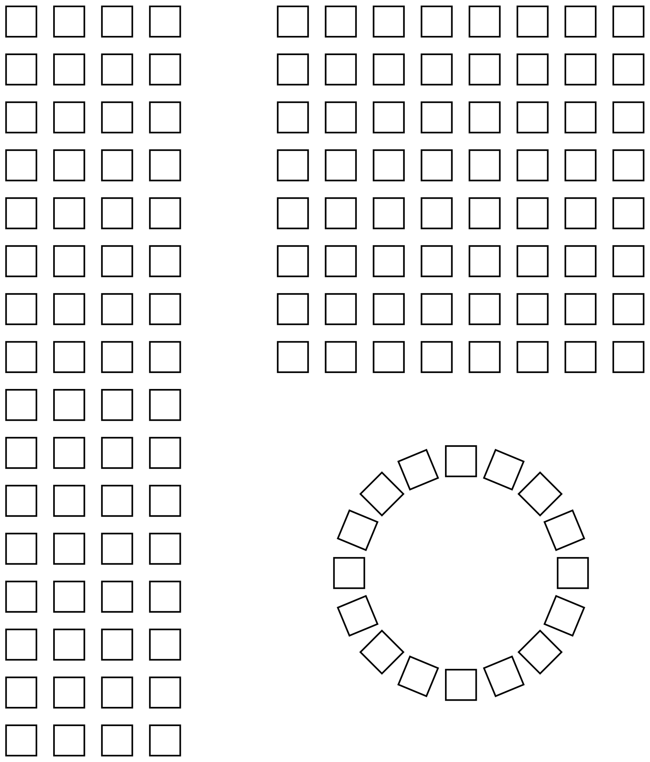
Figure 7Antenna array configurations for next generation mobile communication base stations (Airrays GmbH, 2016). Outdoor units: 4×16 and 8×8 elements. Indoor unit: 16 elements arranged on a circle (ceiling mounted).
Applying the results presented here, the rotation angles of the elements can be optimized. If e.g. a subgroup size with seven elements is chosen, there are eleven additional rotation angles aside from , as is depicted in Fig. 8.
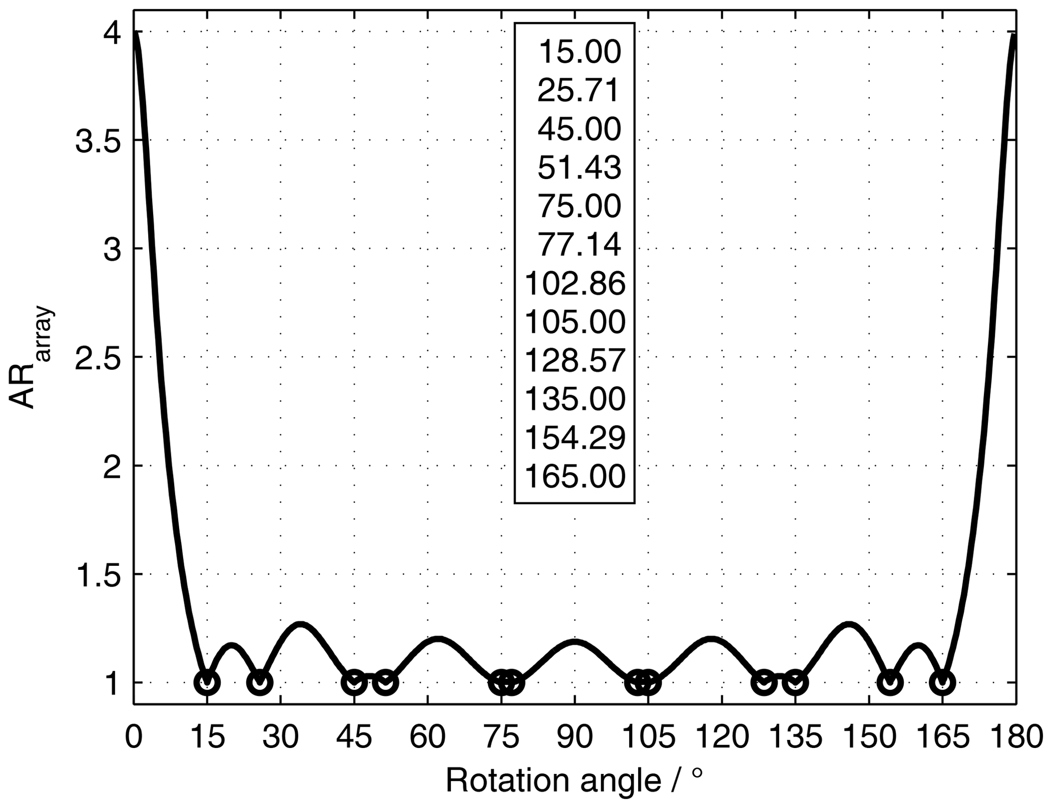
Figure 8AR for antenna arrays with seven sequentially rotated elements vs. rotation angle (ARsingle=4). Angles for ARarray=1 are indicated by circles and the numbers are given in the box.
A small subgroup might be the base for building large planar arrays on a triangular grid, which is shown in Fig. 9 (left, no element rotation shown). For indoor communication, placing antennas in the upper room corners might be preferable, thus a triangular shape as depicted in Fig. 9 (center, no element rotation shown) could be advantageous. In linear antenna array subgroups feeding all elements from one side could be essential for the system design, e.g. to avoid vias (electrical connection between layers) and subsequently unnecessary many layers in PCBs (Printed Circuit Boards). This might lead to choose the rotation angle as small as possible. For a seven element subgroup the smallest rotation angle for ideal CP is 15∘, as is shown in Fig. 9 (right).

Several other scenarios for mobile communication (antennas on pillars, circle segments, conformal arrays) might also profit from using non-standard rotation angles.
In antenna arrays perfect single radiators are not realizable. Unwanted differences between elements will further impede efficient operation. It has been shown in this paper, that a smart approach of placing and rotating the elements on a suitable grid will improve the radiation characteristics of the antenna array. This effect will be most efficient, if the single radiators show only medium polarization quality, like e.g. mass produced inexpensive devices used in IoT applications. This study gives advice to design sequentially rotated antennas with optimized rotation angles.
No software code or research data is available for the presented work, but all results can be reproduced with the equations and parameters given here.
The author has declared that there are no competing interests.
Publisher’s note: Copernicus Publications remains neutral with regard to jurisdictional claims in published maps and institutional affiliations.
This article is part of the special issue “Kleinheubacher Berichte 2021”.
The author would like to thank Frauke Gellersen and Thomas Kleine-Ostmann from PTB for valuable discussions and checking the manuscript (proofreading).
This open-access publication was funded by the Physikalisch-Technische Bundesanstalt.
This paper was edited by Ludger Klinkenbusch and reviewed by two anonymous referees.
5G Lab: 5G Summit, http://www.5gsummit.org/dresden-2016/ (last access: 2 October 2022), 2016. a
Airrays GmbH: Smart basestation antenna for next generation mobile communication, http://www.airrays.com/ (last access: May 2019), 2016. a, b
Hall, P. S. and Smith, M. S.: Reduction of Grating Lobes in Sequentially Rotated Microstrip Patch Arrays, in: Eighth International Conference on Antennas and Propagation, Edinburgh, UK, 30 March–2 April 1993, 364–367, https://ieeexplore.ieee.org/abstract/document/224699 (last access: 2 October 2022), 1993. a
Hall, P. S. and Smith, M. S.: Sequentially Rotated Arrays with Reduced Sidelobe Levels, IEE Proceedings: Microwaves, Antennas and Propagation, 141, 321–325, https://doi.org/10.1049/ip-map:19941193 , 1994. a
Hall, P. S., Huang, J., Rammons, E., and Roederer, A.: Gain of Circularly Polarised Arrays Composed of Linearly Polarised Elements, Electron. Lett., 25, 124–125, 1989. a
Huang, J.: A Technique for an Array to generate Circular Polarization with Linearly Polarized Elements, IEEE T. Antenn. Propag., 34, 1113–1124, https://doi.org/10.1109/TAP.1986.1143953, 1986. a
Jaschke, T.: Substrate integrated waveguide technology for Rx/Tx integrated array antennas, PhD thesis, Technische Universität Hamburg, https://doi.org/10.15480/882.3648, 2021. a
Kuhlmann, K.: Hochintegrierte aktive Sendeantenne für den Millimeterwellenbereich, PhD thesis, Technische Universität Hamburg-Harburg, https://doi.org/10.15480/882.1086 , 2013. a, b
Kuhlmann, K.: Sequential Rotation of Antenna Array Elements – Rotation Angle Optimum, in: Kleinheubacher Tagung, Miltenberg, 28–30 September 2021, https://www.kh2021.de/ (last access: 2 October 2022), 2021. a
Kuhlmann, K. and Jacob, A. F.: Antenna Arrays on Rectangular and Triangular Grids for Polarization Multiplexing – a Comparative Study, in: Proc. German Microwave Conference, Munich, Germany, 1–4, https://doi.org/10.1109/GEMIC.2009.4815896 , 2009. a
Kuhlmann, K. and Jacob, A. F.: Active 30 GHz Antenna Array for Digital Beamforming and Polarization Multiplexing, in: IEEE MTT-S International Microwave Symposium Digest, Anaheim, CA, USA, 1276–1279, https://doi.org/10.1109/MWSYM.2010.5514863 , 2010. a
Pozar, D. M.: Microwave Engineering, 3rd edn., John Wiley & Sons, Inc., ISBN: 9780471644514, 2005. a
Pozar, D. M. and Schaubert, D. H.: Microstrip Antennas: The Analysis and Design of Microstrip Antennas and Arrays, Electrical engineering, antennas and propagation, Wiley, ISBN: 9780780310780, 1995. a
Smith, M. S.: Grating Lobes of Sequentially Rotated Antenna Arrays, in: Seventh International Conference on (IEE) Antennas and Propagation, York, UK, 15–18 April 1991, 217–220, https://ieeexplore.ieee.org/document/98215 (last access: 2 October 2022), 1991. a
Smolders, A. B. and Visser, H. J.: Low Side-Lobe Circularly-Polarized Phased Arrays Using a Random Sequential Rotation Technique, IEEE T. Antenn. Propag., 62, 6476–6481, 2014. a
Thiel, M. and Dreher, A.: Sequential Rotation in a Smart Antenna Terminal for Broadband Communication, in: IEEE Antennas and Propagation Society International Symposium, Monterey, CA, USA, 20–25 June 2004, 145–148, https://doi.org/10.1109/APS.2004.1329574, 2004. a