 | 21 Mar 2023
Interdigital Resonators in Wideband Ridged-Waveguide Filters
Jonas Weindl
Matthias G. Ehrnsperger
Ananto Prasetiadi
Thomas F. Eibert
An interdigital resonator approach for wideband filter applications in ridged-waveguide technology is presented. The interdigital arrangement of the ridged-waveguide resonators ensures stronger coupling between the resonators. As the coupling sections are consequently enlarged by the interdigital arrangement of the resonators, more feasible filter structures are possible at increasing frequencies. The approach itself can be easily implemented with conventional filter synthesis formulas, which is demonstrated by two 20 GHz examples with a bandwidth of 2 GHz and 100 MHz, respectively. The designed filters are subsequently compared to the standard implementation of ridged-waveguide filters.
- Article
(2994 KB) - Full-text XML
- BibTeX
- EndNote


The new communication standards of the fifth and sixth generations (5G/6G) will lead to very high data rates in the gigabit range, which will be in particular realized by the use of frequencies in the millimeter-wave regime. In order to separate different signals from each other, not only a good spurious passband suppression, but also wide passbands of the used filters are necessary. Conventional -based hollow-waveguide filters are easily manufacturable up to very high frequencies, but due to the used TE101-resonators, the first parasitic resonances occur at around 1.5 times the desired midband frequency. Previous strategies for the suppression of such undesired passbands involved the use of -based combline filters (Wenzel, 1971; Matthaei et al., 1980; Cameron et al., 2018), which can push the spurious passbands up to three times the specified midband frequency. With the technology of combline filters, the interdigital arrangement of resonators was investigated (Matthaei, 1962; Abramovicz, 2010), in which consecutive resonators are placed opposite to each other. Due to the consequential increased coupling between the resonators, very broadband filters can be synthesized with this technology. Since combline resonators are based on coaxial transversal-electromagnetic (TEM) lines, an increased midband frequency leads to very little geometrical details, which makes this technology only suitable for filters up to around 20 GHz, because of arising manufacturing difficulties.
A solution for a good spurious passband suppression with better geometric dimensions are single-ridged waveguide filters, which consist of ridged-waveguide resonators, coupled by rectangular hollow-waveguide sections below the cutoff frequency. Closely related to the concept of broadband combline filters (Levy et al., 1997), such microwave filters were first introduced in Craven and Mok (1971) and constitute a highly suitable alternative for suppressing undesired passbands with additional good power handling capability. The reason for this excellent suppression of spurious passbands at higher frequencies can be found in Soto et al. (2009) and Weindl and Eibert (2020). The synthesis and the determination of the filter dimensions can be performed with the well known synthesis formulas presented in Levy (1967), Matthaei et al. (1980), and Cameron et al. (2018). As it is known from the general filter theory, large bandwidths demand strong interresonator coupling. As a consequence, the rectangular hollow-waveguide sections used for coupling are significantly reduced in length and the limited dimensions of milling tools cause manufacturing problems for these broadband filters.
In this contribution, the beneficial size of ridged-waveguide filters is combined with the advantages of the interdigital arrangement of the resonators, known from the combline technology. The consequential stronger coupling between the resonators allows longer coupling sections, which is highly beneficial for the fabrication process of broadband filters with good spurious passband suppression. First the coupling of interdigital ridged-waveguides in comparison to the conventional constellation is investigated. The concept is then integrated into the filter synthesis. Subsequently, a broadband and a narrowband filter are computed in the interdigital technology and compared to the conventional ridged-waveguide filters, afterwards. Both interdigital filter versions possess a very good spurious passband suppression and the dimensions guarantee good producibility. This proves the benefit of an interdigital resonator arrangement for wideband filter structures.
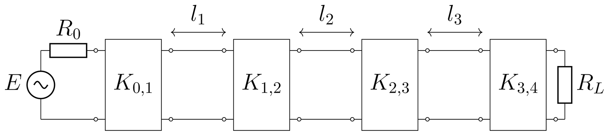
The general equivalent circuit for bandpass filters in waveguide technology is presented in Fig. 1. In the circuit of order three, the different resonators i, realized by waveguide sections of length li are coupled to each other by impedance inverters . Additionally, the first and last resonators are coupled to the input and output impedances. The coupling between resonators can be electric, magnetic or a mix of both (Hong, 2011; Cameron et al., 2018). The validity of Fig. 1 is based on the equivalent representation of coupling through the use of impedance inverters, which can be proven through network transformations. If the desired filter characteristic is specified, the necessary impedances for the inverters can be calculated with the known formulas (Matthaei et al., 1980)
In Eqs. (1)–(3), ν represents the fractional bandwidth of the filter and gi are the so-called lowpass filter prototype values, which can be calculated analytically for a predefined ripple in the passband. The slope parameter χi of resonator i gives information about the behaviour of the resonator around the resonance frequency.
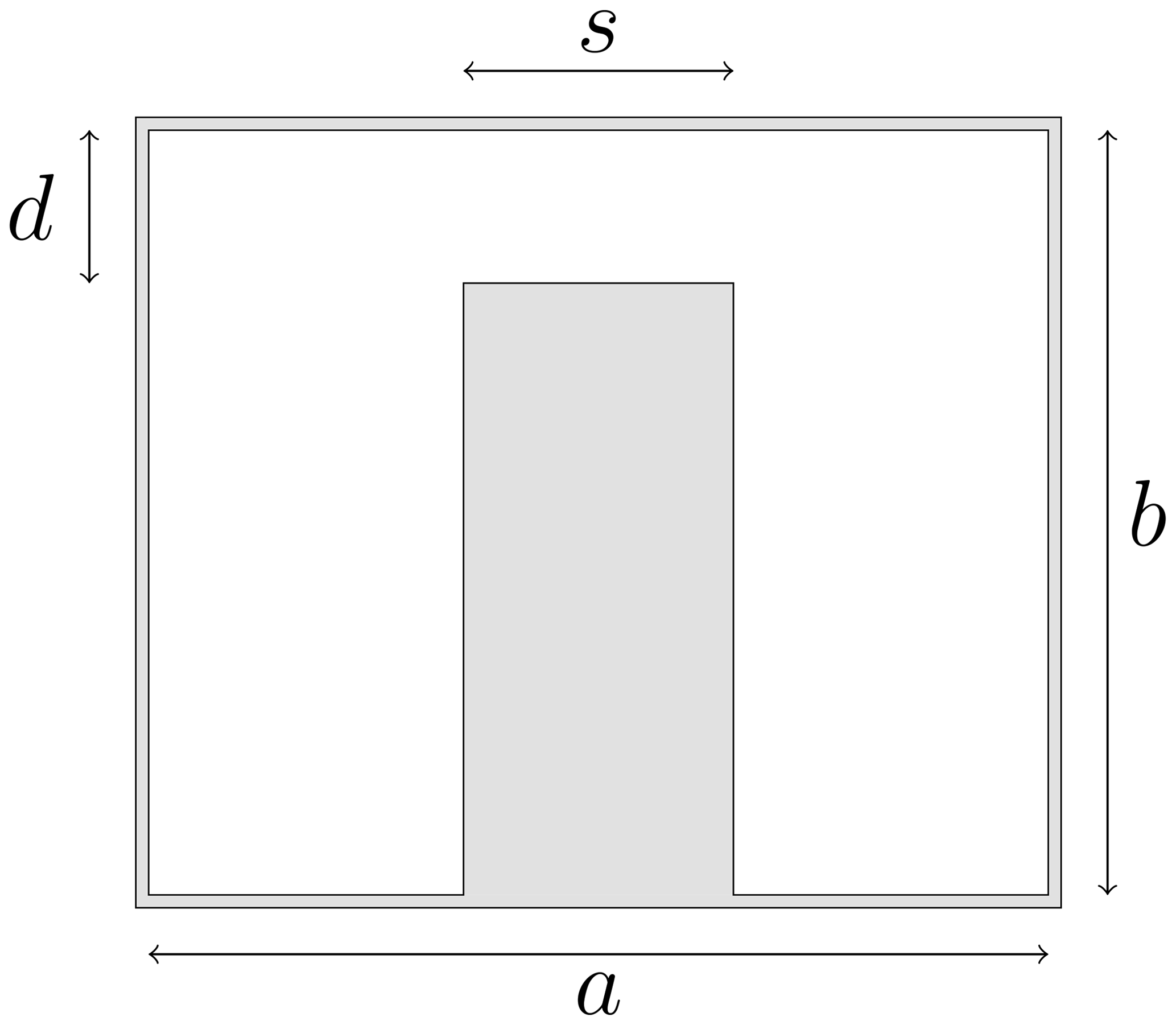
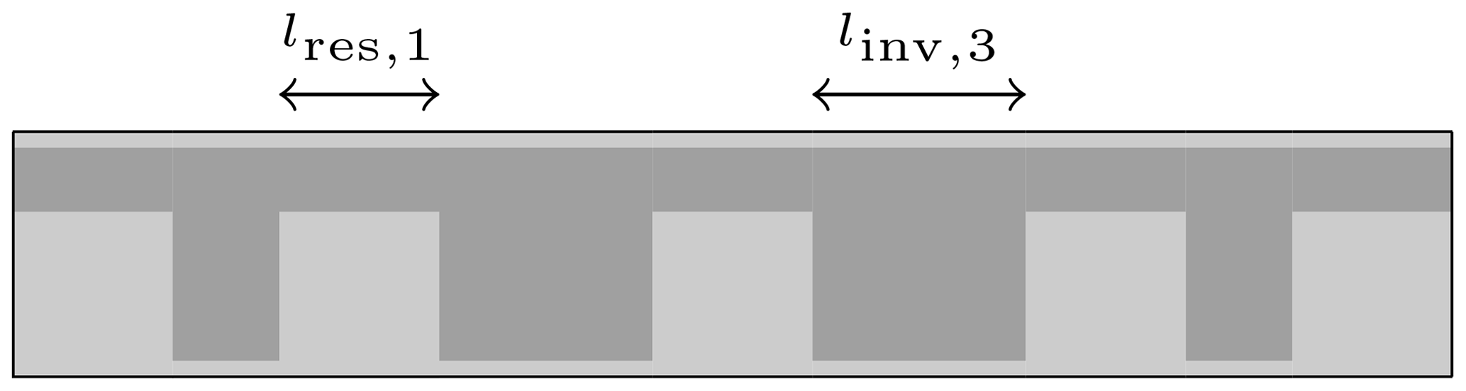
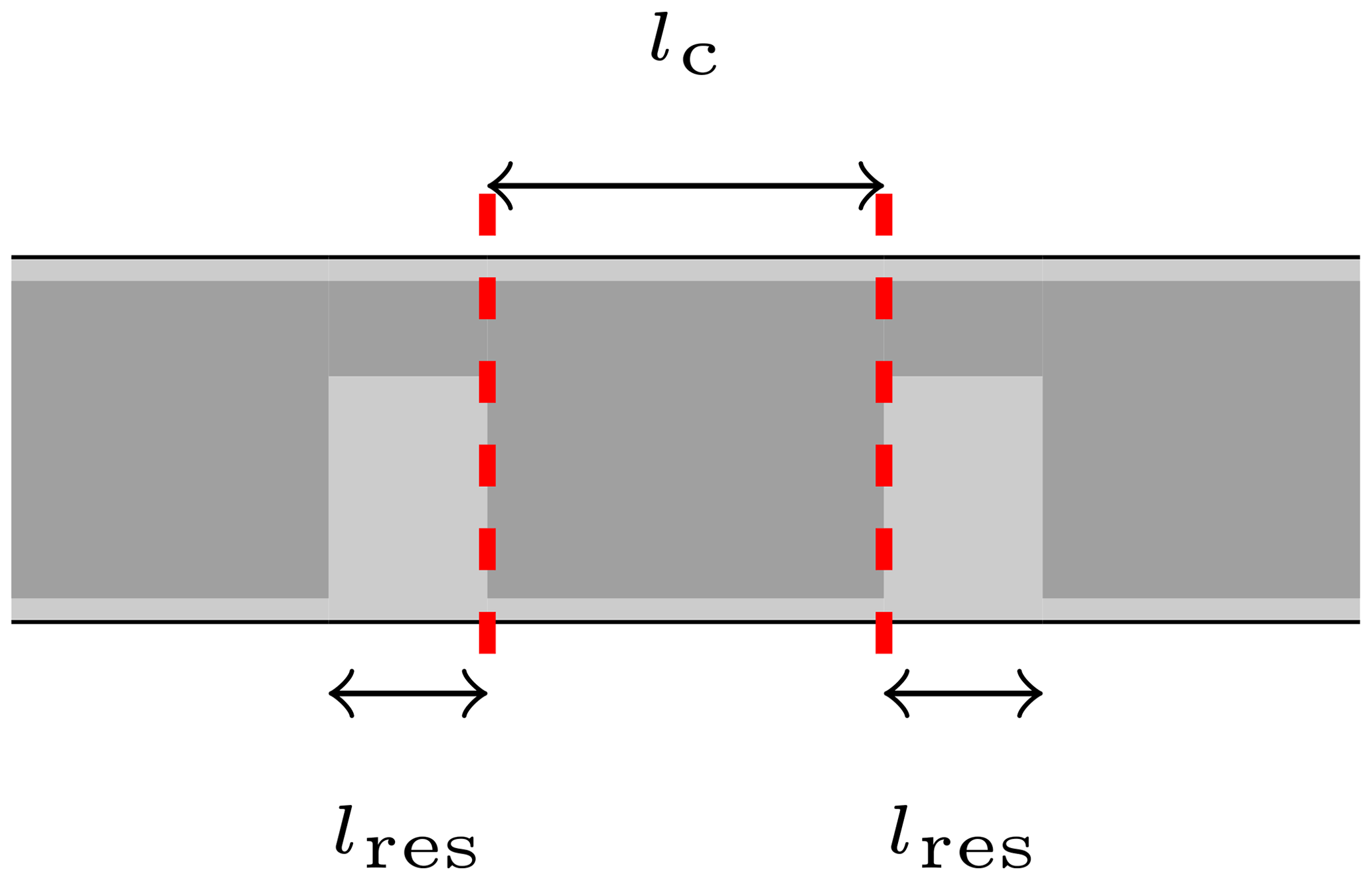
The next step is to use the shown equivalent circuit for the implementation of single ridged-waveguide filters. The cross section of a ridged-waveguide is depicted in Fig. 2. Analogue to rectangular hollow-waveguides, the outer boundary of the waveguide is defined by the parameters a and b. The centered ridge is specified by the ridge width s and the gap d. Due to the ridge, the cutoff frequency of the ridged-waveguide is below the cutoff frequency of a rectangular hollow-waveguide with the same parameters a and b. By defining a certain midband frequency, the waveguide cross sections of the two respective waveguides can be chosen in a way that the first mode of the ridged-waveguide is above the cutoff frequency, whereas the rectangular hollow-waveguide is operated below the cutoff frequency. Since a rectangular hollow-waveguide below cutoff frequency is inductive by nature, it can be used as an inductive coupling element, similar to a coupling iris in conventional rectangular hollow-waveguide filter technology. In Fig. 3, the length cut through a ridged-waveguide filter is depicted. For clarity, the first resonator length lres,1 and the third inverter length linv,3 are marked. The waveguide ridges are drawn in a lighter gray shade and represent the resonators as well as input and output waveguides. After using Eqs. (1)–(3) for calculating the theoretical inverter impedances of the equivalent circuit, the determined values have to be translated to a real waveguide structure. In Levy (1973), it is shown that an impedance inverter can be realized by waveguide discontinuities and negative waveguide lengths. In Fig. 4, the general setup for an impedance inverter between two ridged-resonators is shown. The discontinuities for realizing the inverter are marked with dashed lines. For the S21-parameter between these lines, the expression (Vanin et al., 2004)
can be derived from the ABCD-matrix of an impedance inverter. In Eq. (4), Z0 referes to the characteristic impedance of the waveguide and K describes the desired impedance of the inverter. By varying the coupling length lc of the rectangular hollow-waveguide section, the inverter values can be adjusted accordingly. It can be shown through Eq. (4) that a larger impedance K corresponds to stronger coupling between the resonators and, therefore, a larger value of S21. Since the inverters in the ridged-waveguide filters are realized by rectangular hollow-waveguide sections below its cutoff frequency, i.e, with attenuation, a larger value of S21 is obtained by a shorter value of lc in Fig. 4. From Eqs. (1)–(3) it can also be deducted that a larger fractional bandwidth leads to larger overall values of inverter impedances. As a consequence, broadband filters require stronger coupling between resonators and, therefore, shorter evanescent waveguide sections between the ridged-waveguide resonators. As mentioned before, these short coupling sections can be problematic for a reliable fabrication of filters, since they are milled out by a cutter with certain dimensions.
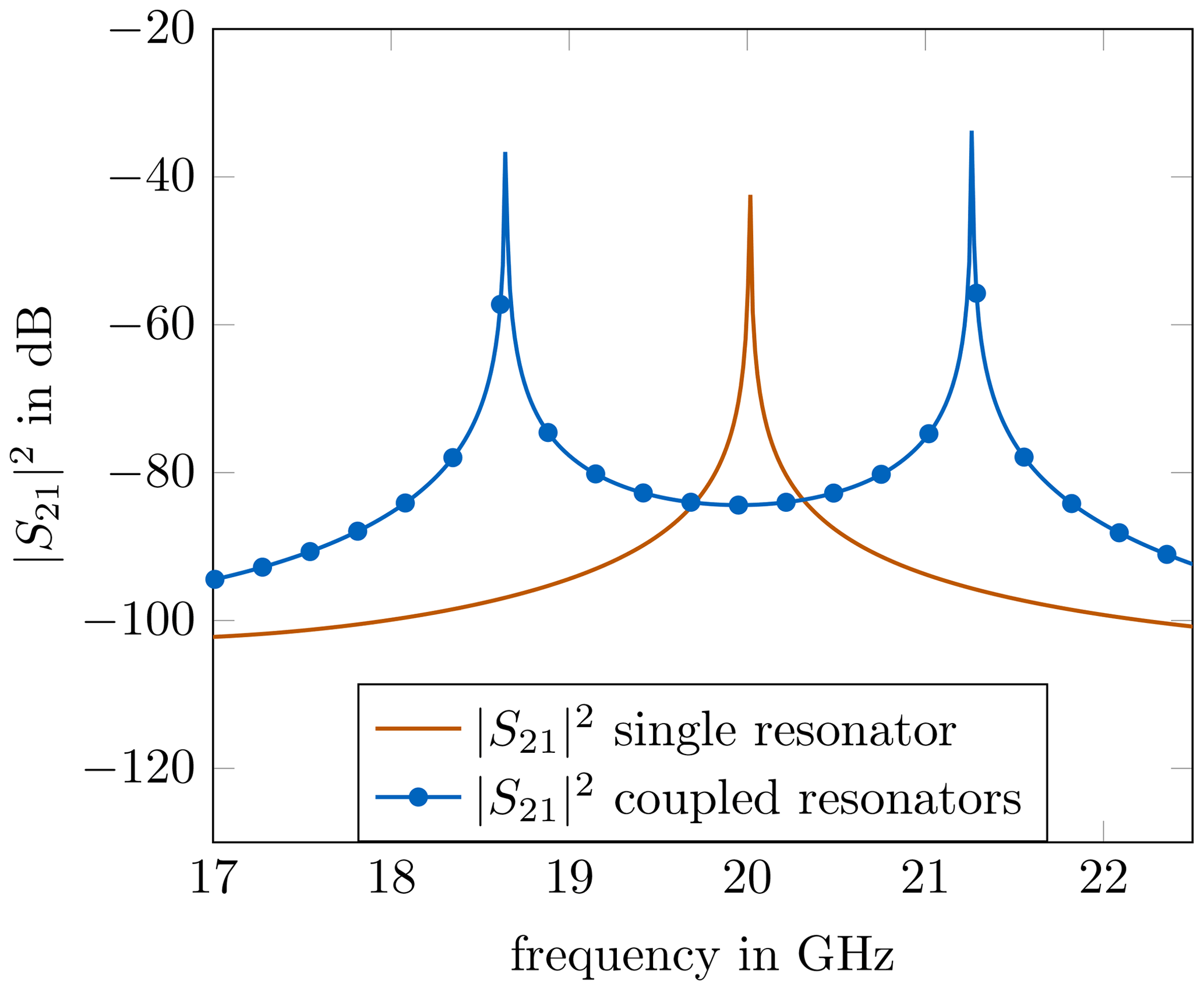
For reliable fabrication, the coupling between the resonators has to be increased. With stronger coupling, the evanescent, rectangular hollow-waveguide sections can be extended without losing the desired filter characteristic. Simple methods for investigating the coupling between two resonators are measurement or simulation, respectively. If all spurious resonances are ignored, a single, uncoupled resonator possesses one resonance peak at the resonance frequency fr, visible by inspection of the scattering parameters. If two of the exact same resonators are coupled to each other, instead of one single resonance peak, two peaks are visible. The stronger the coupling between the resonators, the wider is the separation Δfr of the peaks. The effect of two coupled resonators can be seen in Fig. 5. In this way, it is easy to compare different coupling structures. From Fig. 5, the coupling coefficient M can be extracted by , which gives information about the coupling intensity between the resonators. Most of the time, the coupling coefficient M between resonators is a combination of magnetic coupling Mm and electric coupling Me. The absolute coupling coefficient M then can be approximately described as (Hong, 2011)
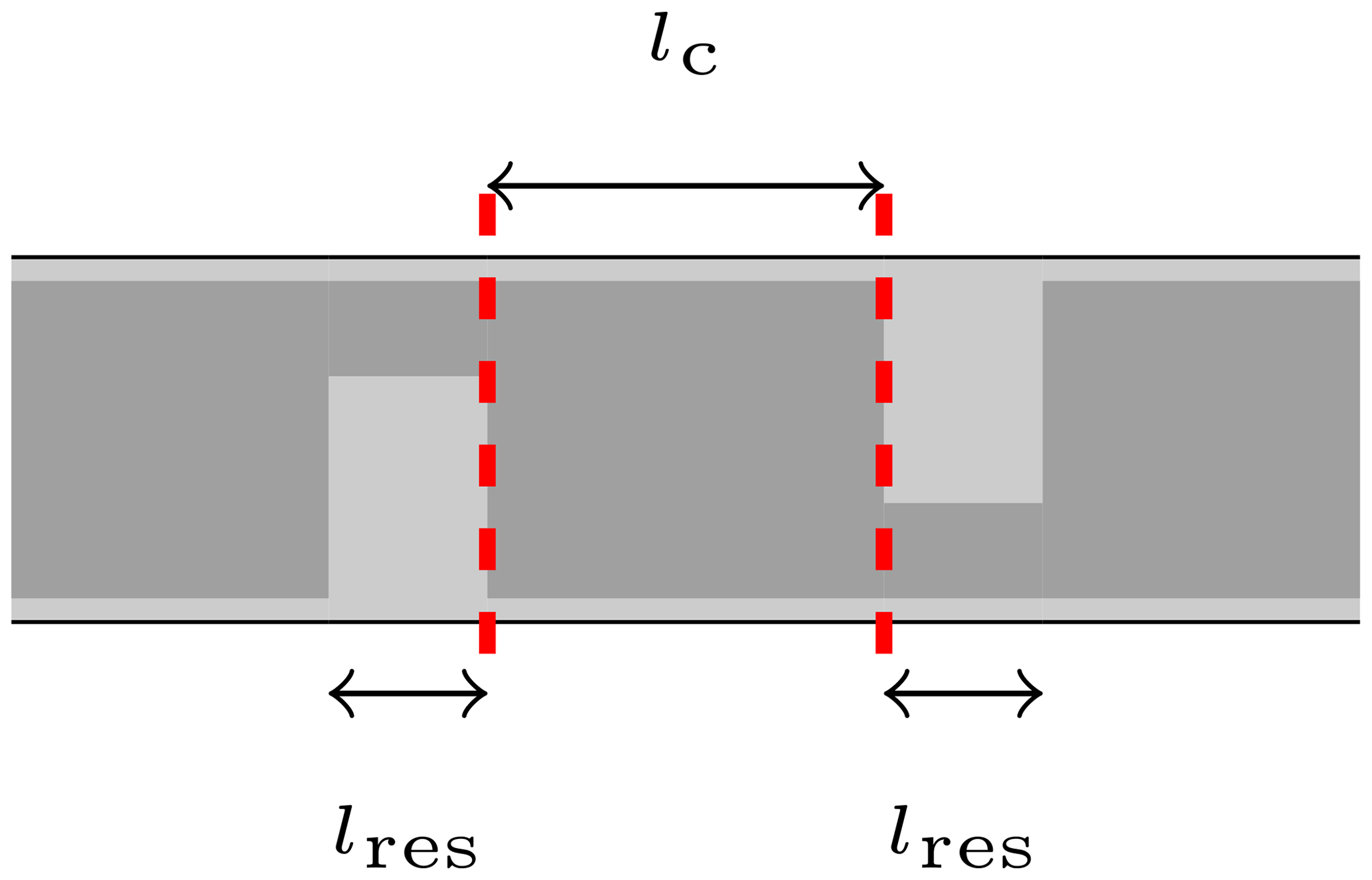
Since electric and magnetic coupling possess a different sign and compensate each other, a reduction of one coupling effect may result in an increase of the overall coupling between two resonators. Keeping this in mind, a possible way to increase the overall coupling for ridged-waveguide resonators, is to decrease the electric coupling by placing the resonators in an interdigital way, as it is depicted in Fig. 6. The interdigital placement of resonators has almost no effect on the magnetic coupling, since the main contribution of this coupling effect is still due to the evanescent hollow-waveguide section, which remains unchanged. However, by positioning the resonators in an opposite manner, the electric coupling is reduced, which, therefore, contributes to an overall stronger coupling. To show this effect, two coupled resonator prototypes were built and measured. Both prototypes consist of the same two resonators, one with conventional resonator arrangement, the other one with the interdigital arrangement. Fig. 7 shows the built prototype with conventional resonator placement.
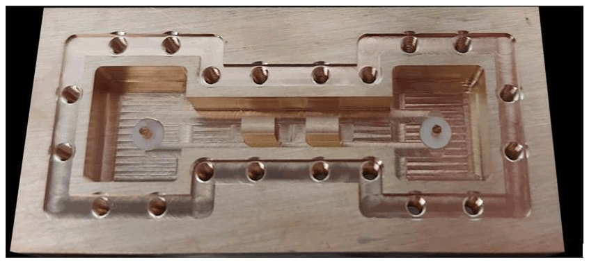
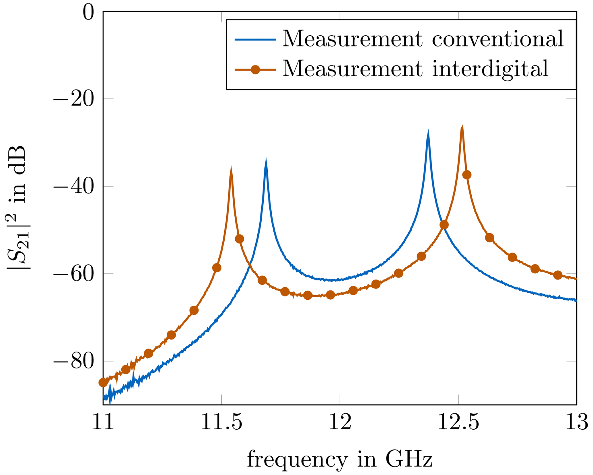
Input and output were realized through coaxial feeding pins, which were loosely coupled to the resonators, in order to reduce disturbing coupling effects. The resonators for both structures where designed for a resonance at 12 GHz and the coupling length lc was set to 4 mm. The open structure was closed with a lid. For the interdigital approach, the second resonator was milled into the lid in order to realize the interdigital resonator constellation. As it can be seen from the measurement results shown in Fig. 8, the resonance peaks of the interdigital resonators do possess a wider separation, which indicates the stronger coupling between the oppositely placed resonators.
Since the first measurements showed good results regarding the improved coupling, a more detailed comparison between the conventional and the interdigital coupling was carried out. With respect to the theoretical filter synthesis, the influence of the coupling length lc in Figs. 4 and 6 on the realized impedance K of the inverters was investigated. The structures of interest were designed for 20 GHz, the cross section dimensions were set to a=3.75 mm, b=3.19 mm, s=1.39 mm and d=0.68 mm. For the electromagnetic computation, the Mode-Matching Technique (Vahldieck et al., 1983; Bornemann and Arndt, 1987; Arndt et al., 1997; Conciauro et al., 2000) was used in order to extract the scattering parameters between the drawn inverter sections. The necessary eigenfunctions of the ridged waveguides were obtained by the use of the Finite Element Method (Jin, 2014). The eigenfunctions for the rectangular hollow-waveguides are analytically well known (Harrington, 1961; Collin, 1990; Jin, 2015). In every step of the procedure, lc was increased and the S21-value between the dashed lines was computed. By solving Eq. (4) for K, the realized inverter impedance of the structure could be determined. The sweep over lc was performed for the conventional constellation as well as the interdigital one. In Fig. 9, the resulting impedances with respect to lc are depicted.
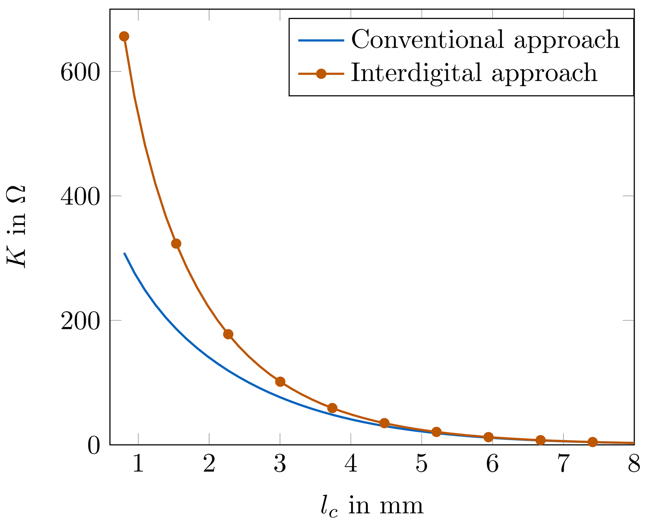
As it can be seen, especially short coupling sections deliver very drastic differences in the realized inverter impedance. For sections of around 1 mm, the impedance of the interdigital approach is more than two times the impedance of the conventional approach. With increasing values for lc, the difference between the two curves in Fig. 9 is reduced. At around 4 mm the difference is almost not visible. The reason for this behaviour can be traced back to the electric coupling between the ridges. For short lc the difference in coupling is large, but with increasing distance of the ridges, the electric coupling is reduced, until it completely vanishes. A suitable analogy is the comparison with a plate capacitor, for which the capacitance is indirectly proportional to the plate distance. The ridges act as the plates in this comparison. If the distance between the plates is large enough, the capacitance vanishes, independent of the conventional or interdigital resonator constellation. The important key message of Fig. 9 lies in the fact that the interdigital approach is especially beneficial for short coupling sections in a filter, which highly supports broadband structures. This is due to the large differences in the inverter impedances for shorter coupling lengths. Additionally, the longest inverter section of a ridged-waveguide filter is the main contributor to the first spurious passband (Soto et al., 2009; Weindl and Eibert, 2020). Since the longest rectangular hollow-waveguide sections do not experience a major enlargement in the interdigital approach, no significant differences in the location of the spurious passband should be expected.
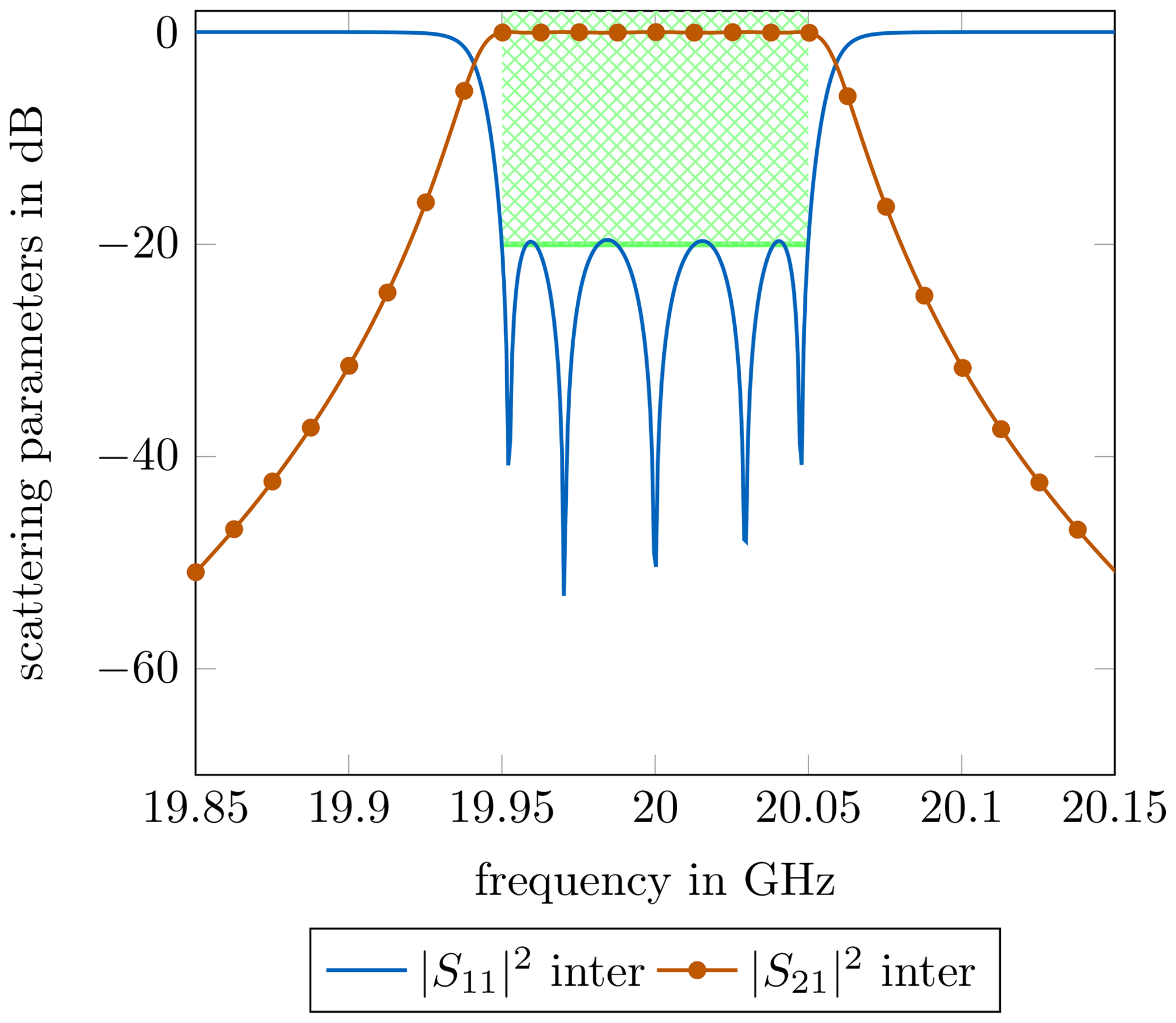
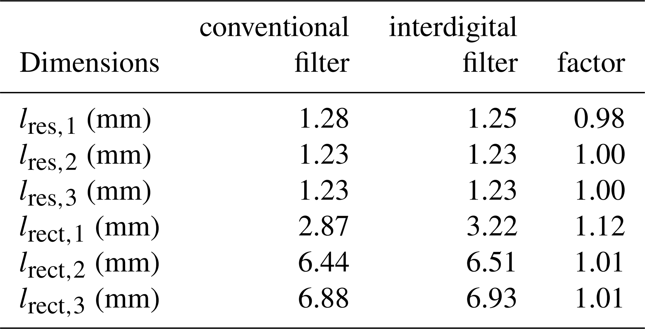
In order to compare the different filter approaches, a Chebyshev bandpass filter of order n=5 for a midband frequency of 20 GHz and a bandwidth of 2 GHz for each approach was designed. The return loss in the passband was set to 20 dB. For both filters the general steps of waveguide filter synthesis were conducted. It should be mentioned that Eqs. (1)–(3) are only valid if the correct slope parameters of the resonators are extracted beforehand. Another possibility is the use of iterative methods, as described in (Vanin et al., 2004; di Crestvolant and Paolis, 2018). Without these measures, the synthesis would lead to unintentionally increased bandwidths. After the first calculations, further optimization of the dimensions was done by an iterative gradient-based method, in order to determine the exact, desired filter curve. In Fig. 10, the simulated passband of the interdigital filter structure is depicted.
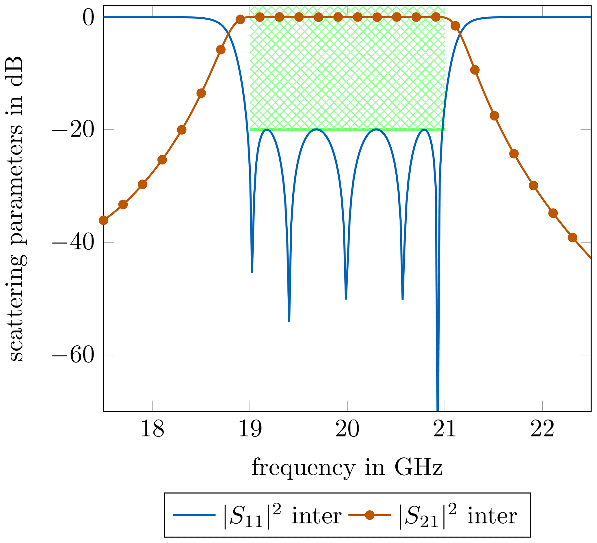
Table 1Broadband filter dimensions of the different approaches.
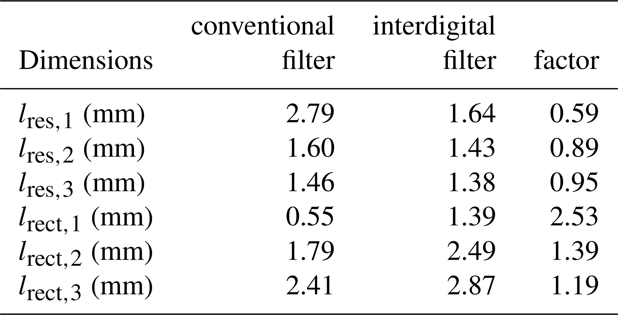
The boundaries for the -parameter are marked in green. As it can be seen, the filter fulfills the predefined specifications perfectly. Since the conventional approach delivered almost the exact same results for the passband, the plot of the simulation was omitted. In Table 1, the resulting dimensions of the waveguide sections as well as the length ratios are listed. Due to the symmetry of Chebyshev filters, the remaining parameters can be deduced from the table. Table 1 shows a major difference in the length of resonator 1. Resonator 2 and resonator 3 result in similar lengths. As expected, the shortest inverter section of the conventional filter is significantly increased by a factor of around 2.5 by the interdigital resonator constellation. The lengths of inverter 2 and inverter 3 are increased as well, but not by the extent of inverter 1.
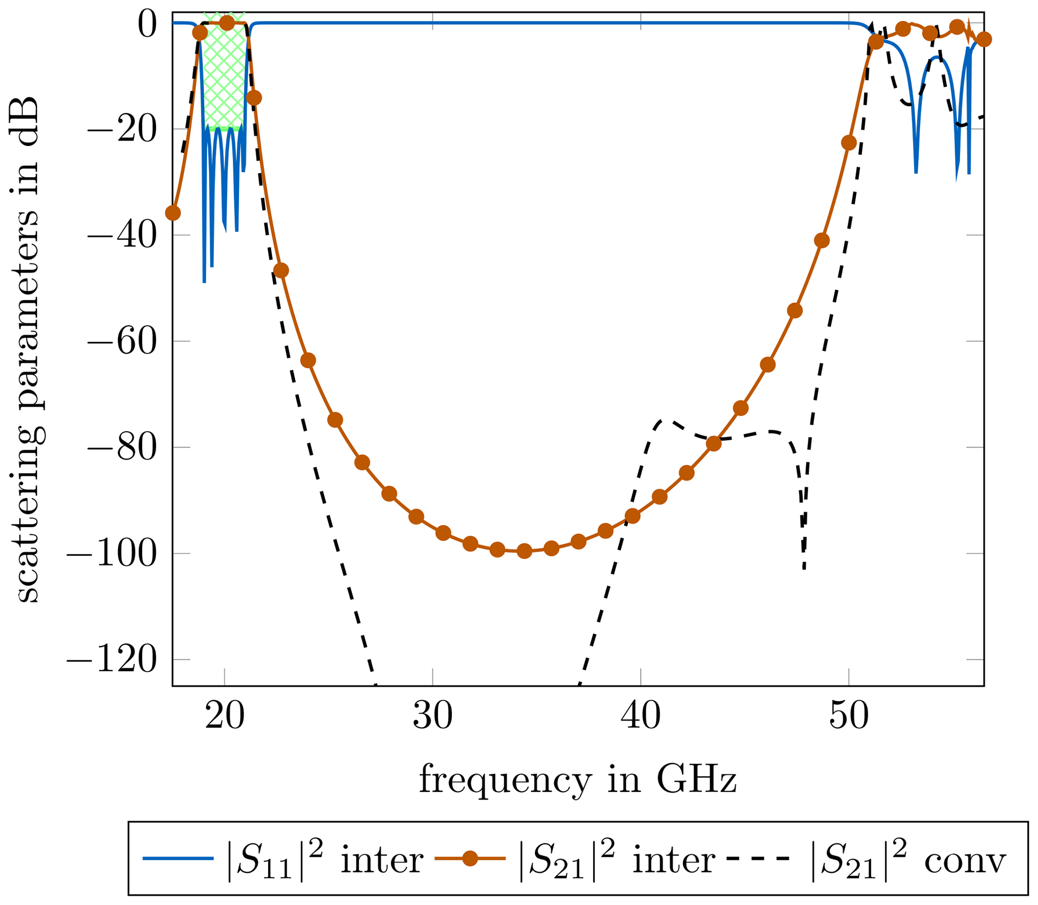
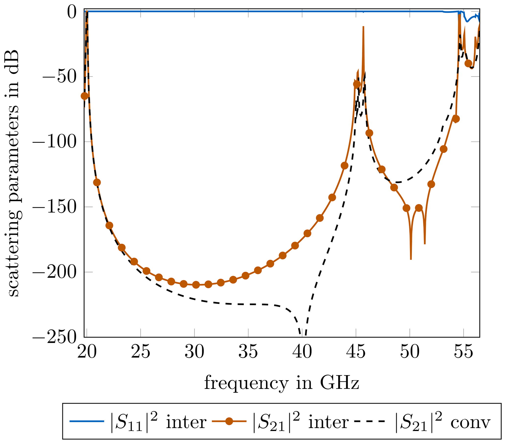
Figure 11 presents the scattering parameters up to 65 GHz. The filter exhibits excellent spurious passband suppression up to 2.5 times the desired midband frequency of 20 GHz. Additionally, the -parameter of the conventional resonator configuration is depicted. As it can be seen, the conventional filter shows a lower -value at around 30 GHz, but it does not introduce any significant difference in the location of the spurious passband regarding the frequency. In summary, both filters show similarly good transmission behaviour, but the interdigital filter has considerable benefits in terms of fabrication.
In the following, the dimensional differences for a 100 MHz narrowband filter are investigated. The scattering parameters of the passband are depicted in Fig. 12, the calculated resonator and inverter lengths as well as length ratios can be found in Table 2.
Table 2Narrowband filter dimensions of the different approaches
For narrow passbands, the coupling between the resonators is significantly smaller than for its broadband counterpart. With regard to Fig. 9, the differences for the coupling lengths are, therefore, very similar to those of the conventional filter. Again, since the longest inverter sections have nearly the same length, the position of the spurious passbands are almost exactly the same, as it can be seen in Fig. 13. As explained in Weindl and Eibert (2020), the spurious resonances now occur at lower frequencies than with the broadband version of the filter.
In summary, this bandwidth comparison makes it clear that the use of interdigital resonators should only be used for wideband applications. For narrowband applications, the conventional method is slightly better and shows a larger insertion loss in the upper frequency regions.
Ridged-waveguide filters are outstanding for bandpass filters with large midband frequencies as well as good spurious passband suppression. Due to the concept of these filters, large bandwidths lead to filter dimensions that are problematic for a reliable fabrication. In this contribution, the use of interdigital resonators within the technology of ridged-waveguide filters was investigated. With the goal of a more dependable fabrication, the presented resonator constellation leads to a stronger coupling between the resonators, which consequently guaranetees more suitable filter dimensions. This can be traced back to an increased length of the coupling structures. Regarding the theoretical synthesis of these filters, special attention was given to the impedance values of the realized impedance inverters. The presented concept was varified by measurements of two coupled-resonator prototypes, as well as the simulation of two conventional as well as interdigital ridged-waveguide filters with a midband frequency of 20 GHz with a bandwidth of 2 GHz and 100 MHz. The synthesized broadband interdigital filter exhibits the desired passband as well as spurious passband suppression, while it maintains filter dimensions, which are beneficial in terms of fabrication.
The underlying research data can be requested from the authors.
AP and JW conceived the presented idea. JW implemented the numerical algorithms for electromagnetic computation and filter synthesis. JW wrote the manuscript in consultation with AP, MGE and TFE. TFE supervised the findings of this work. All authors discussed the results and contributed to the final manuscript.
The contact author has declared that neither they nor their co-authors have any competing interests.
Publisher’s note: Copernicus Publications remains neutral with regard to jurisdictional claims in published maps and institutional affiliations.
This article is part of the special issue “Kleinheubacher Berichte 2021”.
This work was supported in part by the Bayerisches Staatsministerium für Wirtschaft, Energie und Technologie (StMWi) under grant ESB064/002.
This paper was edited by Romanus Dyczij-Edlinger and reviewed by two anonymous referees.
Abramovicz, A.: Modelling of Wide Band Combline and Interdigital Filters, Microwave Review, 2010. a
Arndt, F., Beyer, R., Reiter, J., Sieverding, T., and Wolf, T.: Automated Design of Waveguide Components Using Hybrid Mode-Matching/Numerical EM Building-Blocks in Optimization-Oriented CAD Frameworks-State of the Art and Recent Advances, IEEE Trans. Microw. Theory Technol., 45, 747–760, 1997. a
Bornemann, J. and Arndt, F.: Modal-S-Matrix Design of Optimum Stepped Ridged and Finned Waveguide Transformers, IEEE Trans. Microw. Theory Technol., 35, 561–567, 1987. a
Cameron, R. J., Kudsia, C. M., and Mansour, R. R.: Microwave Filters for Communication Systems: Fundamentals, Design, and Applications, John Wiley & Sons, ISBN 1118274342, Hoboken, New Jersey, 2018. a, b, c
Collin, R. E.: Field Theory of Guided Waves, Wiley, ISBN 978-0-87942-237-0, Hoboken, New Jersey, 1990. a
Conciauro, G., Gugliemi, M., and Sorrentino, R.: Advanced Modal Analysis, John Wiley & Sons, ISBN 978-0-471-97069-9, Hoboken, New Jersey, 2000. a
Craven, G. and Mok, C.: The Design of Evanescent Mode Waveguide Bandpass Filters for a Prescribed Insertion Loss Characteristic, IEEE Trans. Microw. Theory Technol., 19, 295–308, 1971. a
di Crestvolant, V. T. and Paolis, F. D.: Dimensional Synthesis of Evanescent-Mode Ridge Waveguide Bandpass Filters, IEEE Trans. Microw. Theory Technol., 66, 954–961, 2018. a
Harrington, R. F.: Time-Harmonic Electromagnetic Fields, McGraw-Hill, ISBN 9780471208068, New York, New York, 1961. a
Hong, J.-S. H.: Microstrip Filters for RF/Microwave Applications, John Wiley & Sons, Hoboken, New Jersey, 2011. a, b
Jin, J.: The Finite Element Method in Electromagnetics, John Wiley & Sons, 3rd edn., ISBN 978-1-118-57136-1, Hoboken, New Jersey, 2014. a
Jin, J.: Theory and Computation of Electromagnetic Fields, John Wiley & Sons, ISBN 9780470533598, Hoboken, New Jersey, 2015. a
Levy, R.: Theory of Direct-Coupled-Cavity Filters, IEEE Trans. Microw. Theory Technol., 15, 340–348, 1967. a
Levy, R.: A Generalized Design Technique for Practical Distributed Reciprocal Ladder Networks, IEEE Trans. Microw. Theory Technol., 21, 519–526, 1973. a
Levy, R., Yao, H.-W., and Zaki, K.: Transitional Combline/Evanescent-Mode Microwave Filters, IEEE Trans. Microw. Theory Technol., 45, 2094–2099, 1997. a
Matthaei, G.: Interdigital Band-Pass Filters, IRE Trans. Microw. Theory Technol., 10, 479–491, 1962. a
Matthaei, G., Young, L., and Jones, E. M. T.: Microwave Filters, Impedance-Matching Networks, and Coupling Structures, Artech House Inc, ISBN 0890060991, Norwood, Massachusetts, 1980. a, b, c
Soto, P., de Llanos, D., Boria, V. E., Tarín, E., Gimeno, B., Oñoro, A., Hidalgo, I., and Padilla, M. J.: Performance Analysis and Comparison of Symmetrical and Asymmetrical Configurations of Evanescent Mode Ridge Waveguide Filters, Radio Sci., 44, 1–16, 2009. a, b
Vahldieck, R., Bornemann, J., Arndt, F., and Grauerholz, D.: Optimized Waveguide E-Plane Metal Insert Filters for Millimeter-Wave Applications, IEEE Trans. Microw. Theory Technol., 31, 65–69, 1983. a
Vanin, F., Schmitt, D., and Levy, R.: Dimensional Synthesis for Wide-Band Waveguide Filters and Diplexers, IEEE Trans. Microw. Theory Technol., 52, 2488–2495, 2004. a, b
Weindl, J. and Eibert, T. F.: Study of Spurious Passbands of Ridged Hollow Waveguide Filters, German Microwave Conference (GeMiC), 9–11 March 2020, Cottbus, Germany, ISBN 978-3-9820-3971-8, 2020. a, b, c
Wenzel, R.: Synthesis of Combline and Capacitively Loaded Interdigital Bandpass Filters of Arbitrary Bandwidth, IEEE Trans. Microw. Theory Technol., 19, 678–686, 1971. a