Influence of LO cable movements on VNA measurements using Frequency Extensions
Frauke Kathinka Helene Gellersen
David Ulm
Florian Rausche
Andreas Tobias Schramm
Karsten Kuhlmann
In this study, the impact of local oscillator cable movements or drift during VNA measurements using frequency extenders is investigated. A non-reciprocal measurement error caused by alterations of the local oscillator signal in R 900 (WR 10) waveguide measurements from 75 to 110 GHz is observed and systematically analyzed. Furthermore, the theory behind this effect and its implications on measurement results are discussed, as well as possible corrections for both calibrated and raw measurement data.
- Article
(4234 KB) - Full-text XML
- BibTeX
- EndNote
In vector network analyzer (VNA) set-ups with two or more test ports, cable movements are often a significant source of measurement uncertainty (MU). When utilizing VNA frequency extenders, instead of using a VNA base unit alone, all cables connecting each extender to the VNA could be moved and are potential MU sources. In some cases, a considerable cable movement is required, e.g. in set-ups used for the characterization of large devices under tests (DUTs) or antennas. Each VNA extender is usually connected with a local oscillator (LO) cable, a radio frequency (RF) cable and two intermediate frequency (IF) cables to a VNA base unit. While LO cable movements are the primary influence on the LO signal during measurements in laboratories with stable set-ups and good environmental control, similar changes in the LO signal could also arise from temperature fluctuations or drift under less ideal conditions.
Measurement errors resulting from these cable movements, as demonstrated in Novotny (2019) and Arsenovic (2020), may be underestimated or overlooked. Often, reflection measurements are utilized to assess cable stability, yet they remain unaffected by the underlying cause, leading to not detecting and consequently neglecting the issue. When employing conventional methods to account for cable movements and evaluate measurement uncertainties, as outlined in the EURAMET Calibration Guide No. 12 (CG-12) by Zeier et al. (2018) or the METAS VNA Tools Math Reference Federal Institute of Metrology (METAS) (2024), these influences are not comprehensively addressed yet.
In this study, the impact of LO cable movement is systematically investigated. Initially, the theoretical effects of a change in the LO signal at one frequency extender is analyzed and equations for error correction to account for this effect are derived. Additionally, an experiment is conducted employing a phase shifter to methodically examine changes in the LO signal phase during measurements. The phase shifter is integrated into the LO cable path, and the phase value setting is varied from 1 to 10° while measuring the scattering parameters (S-parameters) of a thru connection using R 900 (WR 10) VNA frequency extenders from 75 to 110 GHz. This experimental set-up with a phase shifter facilitates a systematic analysis of the effects discussed by Novotny (2019) and Arsenovic (2020), establishing a connection to theoretical considerations.
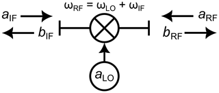
An ideal RF mixer, as depicted in Fig. 1, can be described by a simple S-parameter matrix according to Willliams et al. (2005). Therefore, the incident wave aRF can be related to the outgoing wave bIF by a factor aLO, which depends on the phase of the LO signal at the mixer input
Most commonly, mixers are operated in saturation. Therefore, a change in the amplitude of the LO signal has a minor effect on the output signal, and the factor aLO describes only a change in the LO signal phase. In this work the effect of the LO signal amplitude change due to the cable movement will be neglected ().
Using this simple representation of a mixer, a signal flow graph representing the frequency translating measurement can be drawn. The flow graph in Figure 2 represents the RF section of the forward measurement model. A similar graph can be constructed for the reverse measurement model, as shown by Rytting (2004). The coefficients of the reverse measurement model are named with a prime symbol in this work. Utilizing the presented flow graph, the raw measured S-parameters of the IF and RF signals can be represented as:
The error correction takes into account all constant imperfections of the measurement set-up and VNA itself. However, cable movement during or after calibration is not accounted for by the error correction. Therefore, a term δaLO,3 is considered here. It represents the influence of the LO cable movement after calibration. The change in the raw measured S-parameter values can be expressed as follows:
Equation (3) shows that a cable movement after calibration has no impact on the reflection coefficient measurement, as the same signal is used for up and down conversion. However, from Eq. (4), it can be seen that there is a non-reciprocal impact of the error δ on transmission measurement raw values because LO signals with different phases are now used. The impact of this phase error in the LO signal is identical for forward and backward transmission; only the sign differs.
However, in practice, reflection measurements are commonly employed to test the impact of cable movements, as presented in the CG-12 (Zeier et al., 2018). The results from such tests are not directly applicable to transmission measurements.
2.1 Compensation of the LO phase error
The error corrected transmission terms using the 12-term model with frequency conversion are
Here, the coefficients with a prime symbol belong to the reverse measurement and e30 denotes cross-talk, which is commonly negligible and not shown in Fig. 2. For measurements with negligible cross-talk, meaning , the reflection parameters S11 and S22, as well as the factor D, are immune to the error caused by LO cable movement after calibration because the error is compensated by a product of and .
Without cross-talk the transmission parameters in Eq. (5) can be rewritten using Eq. (4) to
Therefore, the transmission factor of the DUT in both the forward and backward direction can be described as the product of a true value and with a complex phase-shifting term δ. In the case of negligible cross-talk, this term δ is identical for raw and calibrated measurement results. The true values are
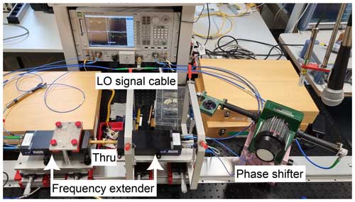
In the experiment shown in Fig. 3, R 900 (WR 10) VNA frequency extenders in the range of 75 to 110 GHz are used. To examine the impact of changes in the LO signal, a phase shifter is introduced into the LO signal path of one extender. A thru reflect line (TRL) calibration is performed and a direct thru connection of the waveguide interfaces in the reference plane is measured repeatedly with different phase shifter settings. This set-up enables systematic investigation of the effects of a change in the LO signal as it might be caused by drift or cable movements after calibration.

Figure 3Overview of the measurement set-up using WR-10 waveguide extenders and a phase shifter in the LO signal path.

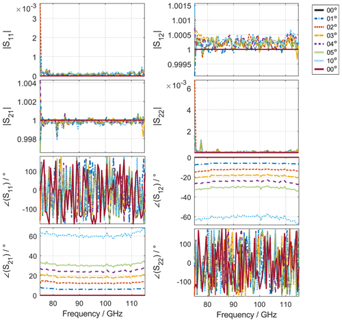
Figure 4S-Parameter measurement results for a thru with phase shifter settings from 0 to 10° in the LO signal path.
The measurement result depicted in Fig. 4 confirms the expectations from the theory discussed in Sect. 2, that the LO signal phase has only a minor impact on the magnitude of the thru S-parameters, while there is a significant impact on the measured phase of the transmission parameter of the thru. Due to noise, it is not possible to make reliable statements regarding the phase of the well-matched reflection parameters of the thru connection. This results from the multiplication of the LO signal in the VNA extender box.
The multiplication factor N for the LO signal in the R 900 VNA extenders used here is N=6. Therefore, adjusting the phase shifter in the LO signal path to α causes a phase shift at VNA port two of approximately N⋅α in the aRF,3 and bRF,3 waves. Figure 4 confirms this; for example, a setting of 1° results in a phase shift of 6° in the measured result. Additionally, it is evident that the phase of the two transmission coefficients is affected with opposite signs. We conducted measurements with the phase shifter setting of 0° as both the first and last measurement. However, the results demonstrate high repeatability, and no discernible difference can be observed from the plot in Fig. 4.
The phase error δ caused by LO cable movements after calibration can be determined by measuring one reciprocal DUT in each cable position and using . All measurements in one cable position can then be corrected using
Since the phase error δ can only be determined unambiguously within ±180°, the LO signal cable movement should still be kept to a minimum. However, for most cables and scenarios this should be no problem.

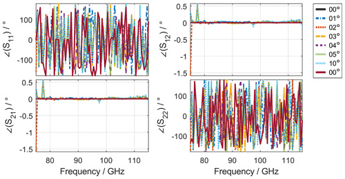
Figure 5Phase angle measurement result shown in Fig. 4 with applied correction making the phase angle of the Thru measurements reciprocal.
In Fig. 5, the phase angle of the measurement result is shown again, this time with the correction applied. It can be observed that the measurement result for the phase angle of thru connections is now almost independent of the setting of the phase shifter in the LO signal path, confirming the proposed correction in Eq. (11). In most measurement scenarios, it is sufficient to move only one frequency extender. However, if cable movements on several ports are necessary or there is significant drift for another reason, this correction can be applied simultaneously to several ports. This is because the errors from the LO signal change on each port are linearly superimposed in the measurement result.
Alternatively, the LO cable movement could be characterized and regarded as a source of measurement uncertainty for the transmission coefficient phase. However, due to the multiplication factor α of the VNA frequency extenders, this MU contribution would be rather significant. In Schramm et al. (2024), measurement uncertainties and uncertainty budgets for waveguide measurements are presented. The additional term due to local oscillator cable movement would presumably dominate the uncertainty budgets for the phase angle of the transmission terms. Therefore, a correction is preferable.
In this study, we explored the impact of LO signal variations in VNA measurements, akin to the disturbances induced by cable movements post-calibration. Through theoretical analysis and experimental demonstrations utilizing a phase shifter to intentionally induce signal variations, we systematically examined the effect of LO signal changes. Our experiment demonstrated that even minor phase changes in the LO signal after calibration can significantly affect the measured phase angle of the transmission coefficients, attributed to the multiplication factor N of the VNA frequency extenders. By deriving error correction terms, including the frequency translating components, we formulated a correction method for the non-reciprocal error and applied it to our experimental data. Our results demonstrate that the corrected measurements remain unaffected by fluctuations in the LO signal, underscoring the robustness of our correction approach. This study contributes to enhancing the accuracy and reliability of VNA measurements, particularly in scenarios where LO signal variations could potentially introduce errors.
There is no significant code to publish. The evaluation was conducted using VNA-Tools [2], and the mathematical operations for generating the plots are straightforward and can be easily reproduced by others.
No data is provided with this publication. However, the measurements can be easily reproduced, as we describe the effect for one of our setups in detail. Readers are encouraged to observe the effect using their own setups, as the focus is on the phenomenon itself, not the specific numerical values.
FG wrote the manuscript, evaluated the measurements and applied the correction to the results. DU came up with the problem and derived the equations describing the effect. FR came up with the measurement set-up and performed the measurements. AS helped with evaluation, writing and discussions. KK provided ideas and was a part of discussions in every step of this study and worked on the manuscript.
The contact author has declared that none of the authors has any competing interests.
Publisher’s note: Copernicus Publications remains neutral with regard to jurisdictional claims made in the text, published maps, institutional affiliations, or any other geographical representation in this paper. While Copernicus Publications makes every effort to include appropriate place names, the final responsibility lies with the authors.
This article is part of the special issue “Kleinheubacher Berichte 2023”. It is a result of the Kleinheubacher Tagung 2023, Miltenberg, Germany, 26–28 September 2023.
The authors would like to thank ChatGPT 3.5 for spell checking this manuscript.
This open-access publication was funded by the Physikalisch-Technische Bundesanstalt.
This paper was edited by Frank Gronwald and reviewed by Mathias Magdowski and one anonymous referee.
Arsenovic, A.: A Method to Remove the Effects of LO Drift from Vector Network Analyzer Measurements, in: 2020 94th ARFTG Microwave Measurement Symposium (ARFTG), 1–5 pp., https://doi.org/10.1109/ARFTG47584.2020.9071755, 2020. a, b
Federal Institute of Metrology (METAS): VNA Tools for reliable RF and Microwave measurements, online, https://www.metas.ch/metas/en/home/fabe/hochfrequenz/vna-tools.html (last access: 28 March 2024), 2024. a
Novotny, D. R.: Reducing Effects of LO Cable Movement in Antenna and Long Distance VNA Measurements, in: 2019 Joint International Symposium on Electromagnetic Compatibility, Sapporo and Asia-Pacific International Symposium on Electromagnetic Compatibility (EMC Sapporo/APEMC), 585–588 pp., https://doi.org/10.23919/EMCTokyo.2019.8893880, 2019. a, b
Rytting, D.: Network analyzer error models and calibration methods, 34 pp., https://citeseerx.ist.psu.edu/document?repid=rep1&type=pdf&doi=033bc80e493bb3da1a6a1dcbebf95c99d6d90317 (last access: 23 October 2024), 2004. a
Schramm, A. T., Gellersen, F. K. H., and Kuhlmann, K.: Uncertainties of S-Parameter Measurements in Rectangular Waveguides at PTB, Adv. Radio Sci., 22, 35–45, https://doi.org/10.5194/ars-22-35-2024, 2024. a
Willliams, D., Ndagijimana, F., Remley, K. A., Dunsmore, J., and Hubert, S.: Scattering-Parameter Models and Representations, IEEE T. Microw. Theory, 314–321, https://doi.org/10.1109/TMTT.2004.839917, 2005. a, b
Zeier, M., Allal, D., and Judaschke, R.: Guidelines on the Evaluation of Vector Network Analysers (VNA), ISBN 978-3-942992-51-0, https://www.euramet.org/Media/news/I-CAL-GUI-012_Calibration_Guide_No._12.web.pdf (last access: 23 October 2024), 2018. a, b


