 | 21 Oct 2025
Frequency-Selective Dual Linearly Polarized 76 to 81 GHz Automotive Radar System Concept for Street Condition Monitoring
Sadam Hussain Kazimi
Waqar Ali Shah
Sascha Reuner
Dennis Vollbracht
Madhukar Chandra
This study introduces a novel frequency-selective radar system for street condition monitoring (SCM) that eliminates the cost-intensive dedicated monolithic microwave integrated circuit (MMIC) channels approach by sharing radar channels across different frequency bands. The proposed design uses a step-impedance filter (SIF) to allow the radar to perform standard operations at 76.5 GHz while adding SCM capabilities at 80.5 GHz. The radar system ensures robust frequency selectivity, meeting strict isolation requirements to minimize mutual coupling between the antennas operating at different frequencies. An intensive investigation is conducted to determine the minimum co-polar to cross-polar isolation required for effective frequency-selectivity in the system. Simulations show how the SCM antenna affects the primary radar antenna at 76.5 GHz and how the primary radar antenna affects the SCM antenna at 80.5 GHz. The results confirm that this design can integrate SCM without affecting the main radar's performance, offering a practical and cost-effective solution for autonomous vehicles.
- Article
(3463 KB) - Full-text XML
- BibTeX
- EndNote


The development of automotive radar technology has significantly enhanced autonomous driving systems, particularly in improving environmental perception and safety. Radar systems play a key role in applications such as adaptive cruise control (ACC), collision avoidance (CA), and lane-keeping assistance. Beyond these conventional uses, radar-based street condition monitoring (SCM) has gained attention for improving vehicle safety under varying street conditions and types. Recent studies have investigated the use of radar systems to classify street surfaces by analyzing their back-scattering properties. For instance, Giallorenzo et al. (2018) investigates the back-scattering characteristics of various street surfaces at 77 GHz, demonstrating the feasibility of distinguishing surface types through polarimetric radar measurements. Similarly, Sarabandi et al. (1997) models and validates the electromagnetic wave scattering from asphalt surfaces at millimeter-wave (mmWave) frequencies, demonstrating the impact of water and ice on back-scatter behavior. These research studies not only highlight the potential of mmWave radar for accurate surface classification but also emphasize challenges such as system complexity and cost.
Expanding on this, Trummer et al. (2018) analyzes polarimetric radar data for both SCM and broader environmental features, such as vegetation and curbs. This study shows how distinct polarimetric patterns can effectively characterize surface types, with asphalt producing clustered patterns and gravel generating more scattered signals. Viikari et al. (2008) investigates dual-frequency band radar (24 and 77 GHz) for street condition detection, demonstrating that water and ice significantly alter back-scattering coefficients. The study emphasizes the consistency of relative back-scattering ratios for surface classification and notes the challenges of integrating it with existing radar systems. Furthermore, Gatesman et al. (2005) investigates polarimetric back-scattering properties across different frequencies from 160 GHz to 1.56 THz, demonstrating how decreasing frequency enhances the separation between co-polarized (HH, VV) and cross-polarized (HV) back-scatter. These findings provide a basis for distinguishing surface types and offer valuable insights for varying street surface classification.
Building on these research, our earlier studies (Kazimi et al., 2024b, a, 2025) developed and validated a dual linearly polarized radar system for SCM at 76 to 81 GHz, achieving up to 89.4 % classification accuracy through real-world measurements and SVM-based analysis. These works covered simulation concepts, antenna prototyping, integration into commercial radar sensors, and measurement campaigns across varied street types (i.e., asphalt, concrete, cobble stone and grass) and conditions (i.e., wet, dry and snow-covered). However, the reliance on dedicated MMIC channels increased cost and reduced flexibility. In this paper, we propose a frequency-selective integration approach that, for the first time, adapts a step-impedance filter (SIF) to separate two closely spaced radar functions at 76.5 GHz for standard MIMO radar and at 80.5 GHz for dual-polarimetric SCM using shared MMIC channels. The system uses a SIF patented in Vollbracht and Varma (2024) to achieve high inter-band isolation, minimal mutual coupling between the two applications, and seamless integration into existing radar systems at reduced cost. Simulation results shows the feasibility of this approach, confirming minimal mutual influence between antennas at the respective frequency bands.
Street condition monitoring is essential for autonomous driving, enabling real-time classification of street types to enhance safety. Our earlier approach described in Kazimi et al. (2024b) used dedicated MMIC channels for SCM, which, while effective, posed cost and scalability challenges due to reduced channel availability for normal radar operations, limiting its widespread adoption. To address this, a frequency-selective radar system is proposed that integrates SCM without requiring additional dedicated channels. The frequency-selectivity can be achieved using filters such as multi-branch resonance filter mentioned in Vollbracht et al. (2024) and Vollbracht and Varma (2024) or a diplexer to isolate the secondary SCM antennas from the main antennas of the sensor. It should be noted that the step-impedance filter (SIF) integrated in this work is based on a component design we first developed in Vollbracht and Varma (2024). In its original form, the SIF was intended solely for frequency band separation in automotive radar front ends for unrelated use cases, without consideration of street condition monitoring (SCM). The present work is, to the best of our knowledge, the first to repurpose and co-optimize this filter for a dual-function architecture in which standard MIMO radar operation at 76.5 GHz and non-MIMO dual-polarimetric SCM at 80.5 GHz share MMIC channels.
Using a step-impedance filter (SIF), the system enables multiplexing of radar functionalities by isolating SCM at 80.5 GHz from primary radar operations at 76.5 GHz. The SIF ensures effective signal routing and strong frequency isolation, maintaining performance while reducing cost.
2.1 System Design
The proposed system consists of three main components:
-
Main Radar's Antenna: Dedicated to standard radar operations at 76.5 GHz, optimized for long-range applications,
-
The Step-Impedance Filter (SIF),
-
Secondary SCM Antenna: Designed to operate at 80.5 GHz for street condition classification, using dual linear polarization for accurate surface detection.
Figure 1 shows a simplified system block diagram, illustrating the integration of the SIF, main radar's antenna, and SCM antenna. The SIF, functioning as a high-pass filter, provides a low-resistance path for higher frequencies (80.5 GHz), enabling frequency-selective signal routing between the MMIC and antennas. It is optimized to support an operational bandwidth of 1.5 GHz (79.5–81 GHz) for SCM while preserving main radar functionality at 76.5 GHz. This design ensures efficient operations and minimal coupling between the two antennas of the radar sensor.
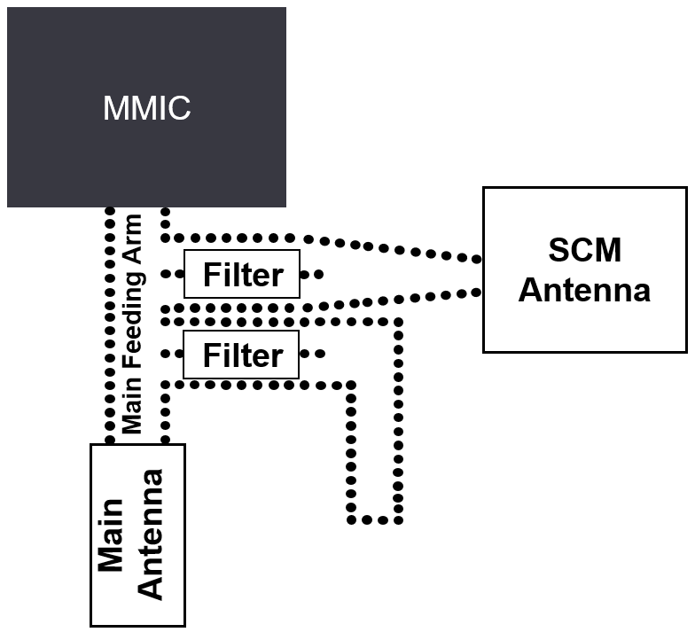
2.1.1 Power Extraction and Routing
To enable dual functionality, the system uses two branch-outs from the main feeding arm. These branch-outs are designed to extract power at 80.5 GHz. After extraction, the power is combined into a single wave-guide to feed the secondary SCM antenna, effectively reducing the power delivered to the main antenna by 6 dB without compromising its operation at 76.5 GHz. The positioning of the branch-outs is important to reduce the losses and efficiently feed the secondary SCM antennas. To achieve this, the branch-outs are placed as close as possible to the input transitions from the MMIC to the main feed arm. This placement reduces transmission losses and ensures efficient power transfer to the secondary SCM antennas. To further enhance isolation between the two antennas operating at different frequencies, the design includes optional additional branch-outs with terminations. These branch-outs extract another 6 dB of power at 80.5 GHz from the main feeding arm, further reducing interference between the radar's main antennas and the SCM antennas.
2.1.2 Integration of the SCM Antenna
To illustrate the practical implementation of the proposed system, the integration of the SCM antennas with two transmitters (TXs) and two receivers (RXs) both in horizontal and vertical polarization within a radar antenna PCB board is considered. For automotive front radar sensors, the antenna PCB typically accommodates between two to four MMICs, with each MMIC capable of handling multiple transmit (TX) and receive (RX) channels. The integration of the SCM antennas can be scaled depending on the number of MMICs available, offering a trade-off between complexity and performance.
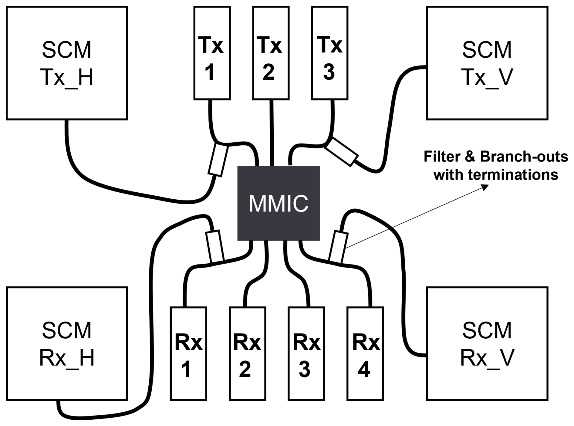
To simplify the explanation and illustrate the concept, an example using a single MMIC is presented in this study. While the actual implementation would involve multiple MMICs (typically 2 to 4) in a full front radar system, this simplified representation focuses on conveying the key idea of frequency selectivity and integration. The MMIC used in this example has 3 TX and 4 RX channels, with frequency selectivity applied to 2 TX and 2 RX channels. The step-impedance filter connects the radar's main antennas and SCM antennas to these channels, enabling the routing to share TX and RX channels between the 2 antennas based on their operating frequencies. Figure 2 presents the schematic layout of this integration, highlighting the placement of the filter and routing connections for the main and SCM antennas. With this approach the fully polarimetric capability is gained for SCM of the sensor at 80.5 GHz in addition to the regular operation of the radar sensor at 76.5 GHz as shown in Eq. (1). The SCM mode can be activated on demand by the modulation scheme based on chirp frequency.
The antenna design in this study follows a systematic approach to achieve high performance while addressing the unique requirements of dual-polarized operation for street condition monitoring. The design process focuses on both the horizontal polarization (H-Pol) and vertical polarization (V-Pol) antennas, with innovative techniques to mitigate mutual coupling effects and optimize performance. The design methodology is generalized here to maintain simplicity and to provide a clear theoretical foundation.
3.1 Design Procedure
The design of the antenna system is divided into the following steps:
-
Linear Slot Array Design and Optimization: The design of the 10-slot linear array is optimized for operation at a center frequency of 80.5 GHz, with a bandwidth of 1.5 GHz, a gain of 22 dBi, and a sidelobe level (SLL) of less than −20 dB. Each slot is designed to achieve resonant conditions, with uniform slot spacing and dimensions calculated using standard waveguide array design principles. The slot length is set to , where λ0 is the free-space wavelength, and to avoid grating lobes the slot-to-slot spacing is kept at , where λg is the guided wavelength. For the traveling wave design, the short-circuit distance is maintained at .
The slot positions and offsets are optimized using Elliott's design procedure (Elliott, 1979; Hosseininejad and Komjani, 2012) to control the impedance and radiated power, ensuring minimal reflection at the feed ports. The generalized relations for the mode voltage Vn between the two cross section and total admittance seen looking into the (n−1)th junction towards the matched load are given by Eqs. (2) and (3). Mode voltages on adjacent junctions are given by Vn where the slot with its equivalent admittance Yn is placed.
and
Modified Elliott's equation for the traveling wave which is based on the dominant mode TE10 without considering the mutual coupling is given by Eq. (4).
where β is the phase constant, dslot is the slot spacing, and fn and fn−1 are functions representing the voltage distribution along the array at the nth and (n−1)th slots, respectively as defined in Elliott (1979). Additionally, and are the corresponding voltage coefficients.
-
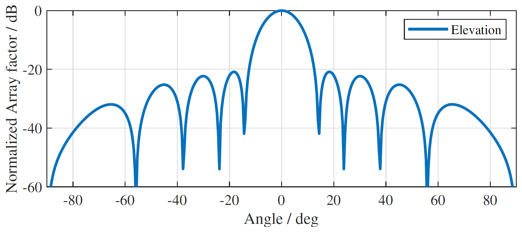
Planar Array Design and Mutual Coupling Compensation: The overall antenna radiation pattern is determined by its array factor (AF). The linear array is extended into a planar configuration to increase gain and coverage. Mutual coupling effects between adjacent arrays are compensated by introducing complementary slots. These shorter, secondary slots are positioned opposite the main slots with an 180° phase shift, effectively storing energy and adjusting the impedance to reduce coupling. The offset for the complementary slots is calculated by Eq. (5).
where fxsmall is the scaling factor and wslot is the slot width. Chebyshev amplitude weighting coefficients are used to synthesize antenna arrays with specified sidelobe levels. The resulting radiation pattern is calculated based on the synthesized excitation of the antenna array slots, which represents the desired amplitude levels for individual slots in the overall radiation pattern, as shown in Fig. 3.
-
Power Divider Design: Develop a power divider to ensure uniform amplitude and phase distribution across all radiating elements. For V-Pol antennas, the divider introduces progressive phase shift of 33° to achieve a beam tilt of −10° in elevation. Equation (6) is used to calculate the required phase input for each stick.
where d is the distance between the slots, θ is the desired beam tilt angle, and λ is the wavelength.
The calculated ΔΦ represents the progressive phase required at each output of the V-Pol power divider. This phase progression is achieved by tilting the feeding network, introducing progressive delays. In the H-Pol array antenna, the elevation pattern is naturally tilted toward the input side with equal-phase feeding. All phase adjustments are controlled through the use of vias in the power divider network.
-
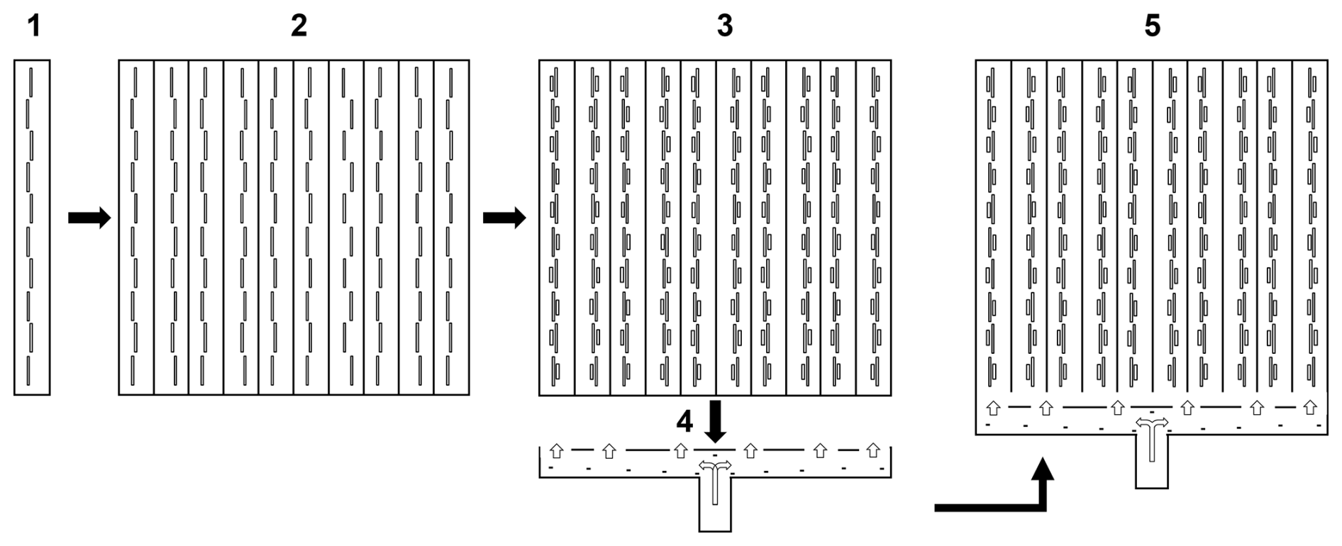
Complete Antenna Optimization: Combine the linear arrays with the power divider, iteratively optimizing slot parameters (length, offset, and spacing) and feed network to achieve the target performance metrics, including input matching, sidelobe suppression, and beam tilt as illustrated in Fig. 4.
3.1.1 Vertical Polarization (V-Pol) Antenna
The V-Pol antenna is based on resonant linear sticks arranged side-by-side. The feeding network includes delay lines that create a progressive phase shift, resulting in a tilted beam in elevation. From array factor calculations, a phase shift of approximately 33° produces the desired −10° beam tilt. The final design achieves:
-
Bandwidth: 79.5–81 GHz with dB.
-
Minimum Gain: 22 dBi
-
Sidelobe Suppression: >20 dB.
3.1.2 Horizontal Polarization (H-Pol) Antenna
The H-Pol antenna uses traveling wave arrays with a slightly larger slot spacing to accommodate the beam tilt requirements. Unlike the V-Pol design, the H-Pol planar array is terminated with a short circuit beyond the last slot to radiate residual power efficiently. The design achieves:
-
Beam Tilt: 10° elevation.
-
Input Matching: dB.
-
Sidelobe Suppression: >20 dB.
3.1.3 Final Integration
The planar arrays for both V-Pol and H-Pol antennas are connected to their respective power dividers as shown in Fig. 5, and further optimizations are carried out to refine the performance. Simulated results show:
-
Input Matching: All ports exhibit dB over 79–81 GHz.
-
Cross-Polarization Isolation: >37 dB in the worst-case scenario.
-
Sidelobe Levels: Maintained below 20 dB in both azimuth and elevation cuts.
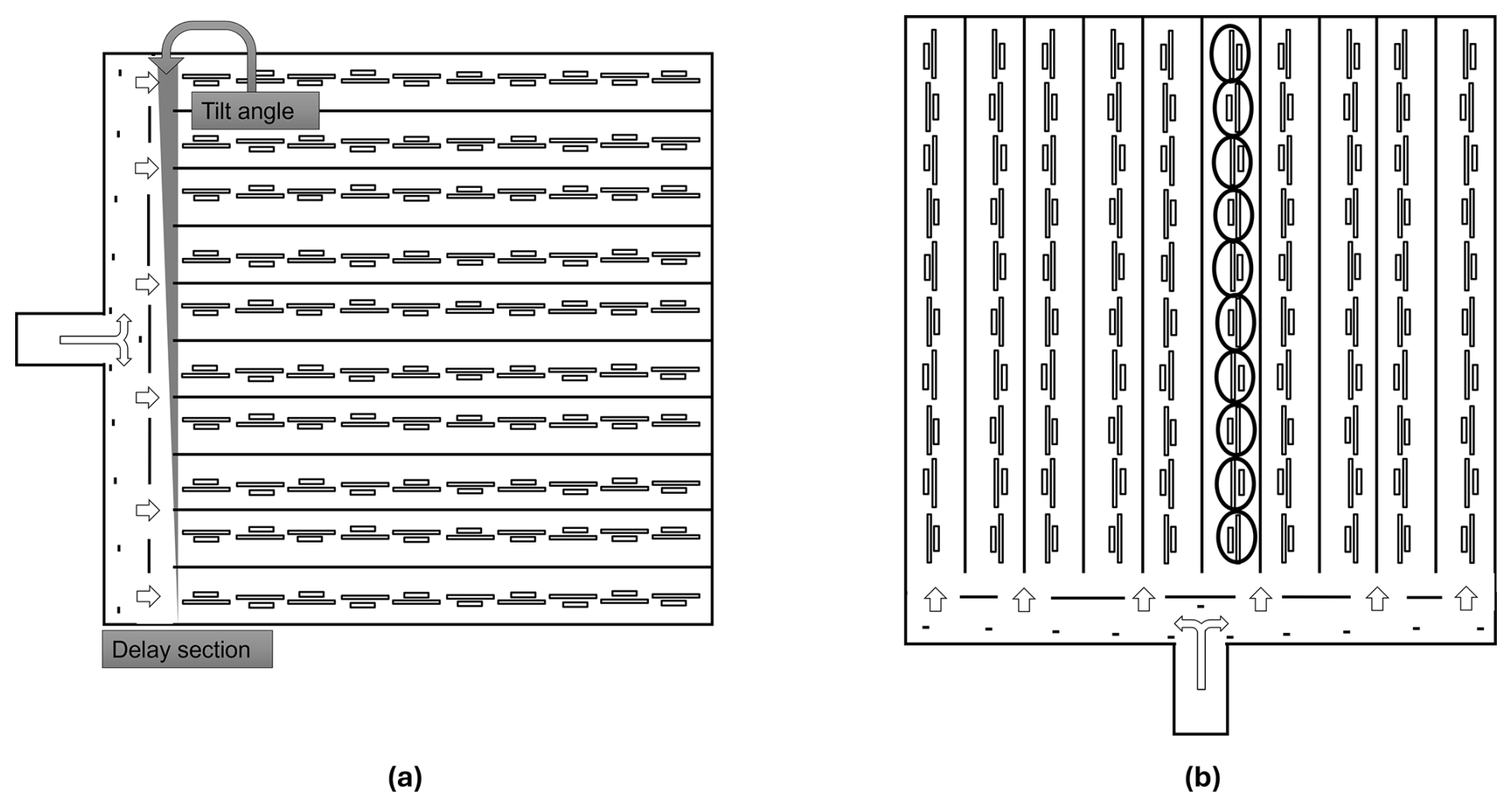
Figure 52D 10×10 antenna array design: (a) Vertical polarization (V-Pol) antenna, (b) Horizontal polarization (H-Pol) antenna.
3.1.4 Antenna Gain Pattern
The antenna gain patterns for both azimuth and elevation cuts of the secondary SCM antenna are shown in Fig. 6. The SCM antenna patterns include co-polarized and cross-polarized components, showcasing key performance metrics such as sidelobe levels, and cross-polarization isolation. These patterns will be used in subsequent simulations to analyze the mutual coupling effects and frequency-selective operation of the system.
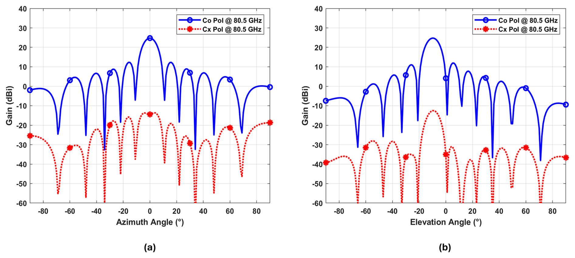
Figure 6Antenna azimuth and elevation cuts from CST array factor calculator: (a) Co and cross-pol azimuth cuts, (b) Co and cross-pol elevation cuts.
To test the performance of the proposed SCM antenna system, detailed simulations were conducted using MATLAB. The simulation parameters and scenarios, including the system link budget, street returns for various street types, conditions, and ego-vehicle's velocities, are explained in details in our previous work (Kazimi et al., 2024b). These simulations have been validated with real-world measurements, as presented in Kazimi et al. (2024a), where street condition monitoring results demonstrated high classification accuracy under different street types and conditions. While this paper aligns with the broader research direction of previous studies, it addresses a fundamental aspect of the system by investigating cross-polarization isolation and its impact on SCM performance, which is a crucial step in the overall development.
4.1 Simulation Objective
The main objective of this simulation study is to determine the minimum co to cross-polarization isolation required for reliable street condition monitoring and investigate the influence of the radiations between the main radar's antennas and secondary SCM antennas at their respective operating frequencies. This investigation identifies the antenna design requirements and evaluates potential induced errors or fault in measurements arising from insufficient isolation and side-lobe levels.
4.2 Simulation Setup and Parameters
The simulations uses a 10×10 SCM antenna array with the gain pattern shown in Fig. 6, and radar link budget summarized in Table 1. A key focus of this investigation is to determine the co to cross-polarization isolation requirements for street condition monitoring, particularly when transmitting with one polarization and receiving with another (e.g., transmit H, receive V, or vice-versa). Each transmit and receive antenna has both co-polarized (Co-Pol) and cross-polarized (Cx-Pol) components. For example, a transmit antenna designed for horizontal polarization (H-Pol) will primarily radiate in horizontal polarization but will also radiate a small fraction of energy in the vertical polarization (V-Pol), representing its cross-polarized component. Similarly, a V-Pol receive antenna will predominantly receive in vertical polarization but will also capture some horizontally polarized energy as its cross-polarized response. The isolation between these co-polarized and cross-polarized components, referred to as cross-polarization isolation, plays a key role in maintaining measurement accuracy.
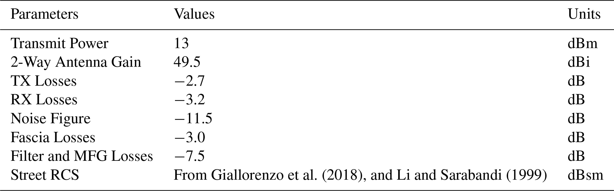
Giallorenzo et al. (2018)Li and Sarabandi (1999)Table 1Key parameters of the simulation for a typical front radar sensor mounted at a height of 0.5 m.
To ensure a reliable street condition monitoring, it is important to have high cross-polarization isolation in both the transmit and receive SCM antennas. This is particularly important in HV and VH configurations, where the radar transmits in one polarization (e.g., H-Pol or V-Pol) and receives in the orthogonal polarization (e.g., V-Pol or H-Pol) receptively. In these scenarios, the isolation must be sufficient to minimize coupling and accurately distinguish between surface backscatter characteristics, such as those caused by depolarization effects from different street types and conditions. The minimum required isolation ensures that the cross-polarized energy is low enough not to introduce significant errors into the measurements, providing clear insight into the scattering behavior of the street surface. These considerations are accounted for in the simulation setup, which include various various transmit and receive configurations, including their Co-Pol and Cx-Pol gain patterns:
-
Transmit Configurations: Horizontal co-polarization (HCo-Pol) and horizontal cross-polarization (HCx-Pol).
-
Radar Cross-Section (RCS) of street: Horizontal tansmit and vertical receive (HV), vertical tansmit and vertical receive (VV), and horizontal tansmit and horizontal receive (HH).
-
Receive Configurations: Vertical co-polarization (VCo-Pol) and vertical cross-polarization (VCx-Pol).
The simulation analysis in this study builds upon the foundational equations derived in our previous work Kazimi et al. (2024b). The radar range equation defined in Eq. (7) is used for calculating the received power (Pr) of the street signal, considering parameters such as transmit power (Pt), antenna transmit gain (Gt), receive gain (Gr), path loss, range (R), noise characteristics, system losses (L), and street RCS (σ), as listed in Table 1.
where λ represents the wavelength of the signal. The power associated with a specific range-Doppler bin (PRD) is given by Eq. (8).
where is the area of a specific range-Doppler bin, Δr represents the range bin width, defined by the range resolution, and Δθ represents the angular width of the azimuth bin. Additionally, the noise per sample is calculated using the Eq. (9).
where NF is the noise figure, k is Boltzmann's constant, Ts the system noise temperature, BW is the base-band bandwidth and N represents the indices of the samples. Additionally, the receiver noise per range bin (Nrange bin) takes into account the system's noise response that considers the base-band noise response along with the noise per sample (Nsample) of the radar system. These equations form the basis for evaluating the radar system's performance in the simulations, including received power, signal-to-noise ratio (SNR), and noise floor calculations, which are crucial for analyzing the SCM antenna array's performance in various scenarios mentioned above.
4.3 Impact of Cross-Polarization Isolation
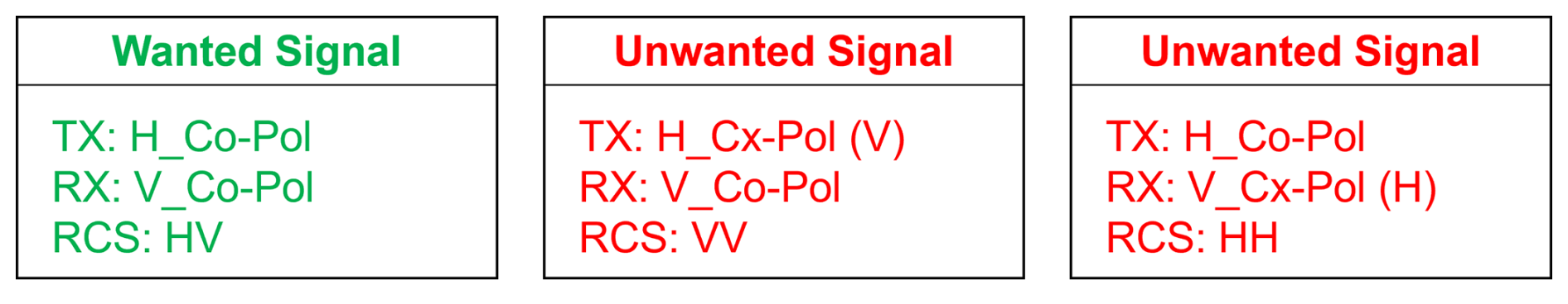
Lets consider the HV configuration, where the antenna transmits in horizontal polarization (H) as its dominant co-polarized component and receives in vertical polarization (V) as its dominant co-polarized component, the wanted signal corresponds to the HV back-scattering from the street surface. However, unwanted signals arise due to the cross-polarized components of the transmit and receive antennas. Specifically, the transmit antenna also radiates a small portion of energy in its cross-polarized component (V), and the receive antenna picks up energy in its cross-polarized component (H). These unwanted signals correspond to the VV and HH back-scattering of the street surface as shown in Fig. 7.
4.3.1 Simulation Results
The simulation investigates the impact of unwanted signals by evaluating their magnitude relative to the magnitude of the main wanted signal. Specifically, the ratio of the wanted signal (HV) to the combined unwanted signals (VV and HH) is calculated. To further evaluate the error-induced and faulty measurements, the magnitude of the combined unwanted signals is normalized with respect to the main wanted signal and added on top of it. This process allows us to quantify the error in terms of dB, representing the measurement inaccuracies caused by the unwanted signals.
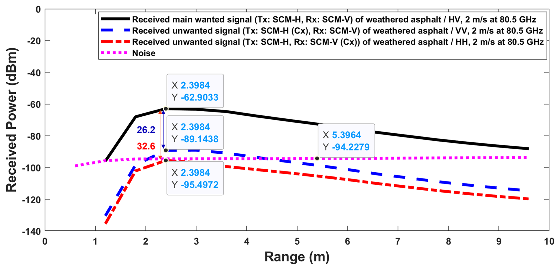
Figure 8Absolute street reception (1 range bin, ego Doppler bin) for wanted and unwanted signals cases of HV configuration.
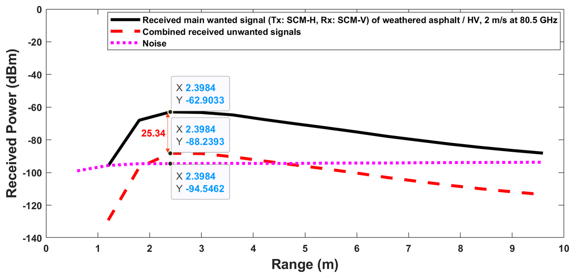
Figure 9Absolute street reception (1 range bin, ego Doppler bin) for wanted and combined unwanted signals of HV configuration.
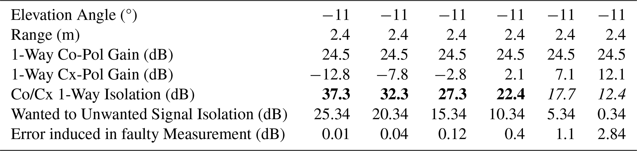
Figure 8 shows the magnitude of the wanted signal alongside the two unwanted signals and the separation between them. While Fig. 9 combines the unwanted signals and calculates the ratio between the magnitude of the wanted signal and the combined unwanted signals. By adding the normalized combined unwanted signals to the wanted signal, an induced error of 0.01 dB is observed. This analysis is conducted under varying cross-polarization isolation levels, starting from the ideal design value of 37.3 dB. The isolation is then progressively reduced in steps of 5 dB to simulate different antenna co-polar to cross-polar isolation configurations. The resulting errors and faulty measurements are quantified for each step. The analysis shows the impact of reduced isolation on the ratio of wanted to unwanted signals and the corresponding induced errors in dB. The results are summarized in Table 2, which provides a detailed comparison of the errors across all isolation levels. This table highlights the minimum cross-polarization isolation required for both transmit and receive antennas to ensure the unwanted signals remain sufficiently suppressed. Maintaining this isolation is crucial for preserving the accuracy of street condition monitoring and minimizing measurement errors.
Table 2Co Cx isolation vs. measurement error and wanted to unwanted signal isolation. Bold values (thick font) indicate the preferred Co Cx 1-way isolation values evaluated as key simulation parameters, while italicized (thin font) values indicate non-preferred cases leading to higher measurement error.
4.3.2 Results Discussion
The simulation results highlight the critical importance of maintaining sufficient co-polar to cross-polar isolation for accurate street condition monitoring. As shown in Table 2, with the designed co-polar to cross-polar one-way isolation of 37.3 dB, the ratio of wanted-to-unwanted signals is 25.34 dB as shown in Fig. 9, inducing a minimal error of only 0.01 dB. However, as the isolation is progressively degraded in 5 dB steps, the wanted-to-unwanted signal ratio decreases significantly (i.e., from 25.34 to 0.34 dB) while the error induced increases from 0.01 dB to 2.84 dB. From these results, a minimum wanted-to-unwanted signal ratio of at least about 10 dB is necessary to maintain reasonable measurement accuracy, which corresponds to a one-way co-to-cross-polar isolation of approximately 22.4 dB. At this point, the error-induced is 0.4 dB, which is borderline acceptable. However, when the isolation drops further to 17.7 dB, the wanted-to-unwanted signal ratio reduces to 5.3 dB, resulting in a significant error of 1.1 dB. Such a high error rate would critically impair street condition monitoring, leading to frequent misclassification of street types and conditions.
4.4 Radiation Between SCM and Main Antenna of the Radar Sensor
In this subsection, the mutual impact between the radar sensor's main antennas, operating at 76.5 GHz, and the SCM antennas, operating at 80.5 GHz is investigated. This analysis evaluates how these antennas affect each other's performance in their respective frequency bands during signal transmission and reception, particularly under channel-sharing conditions. The sensor's antenna board, including signal flow, is introduced, followed by an analysis of antenna gain patterns, simulation results, and a detailed discussion of the findings.
4.4.1 Antenna Board and Signal Flow
The sensor's antenna board consists of two primary components: the radar sensor's main antennas, operating at 76.5 GHz for long-range applications with vertical polarization, and the SCM antennas designed for street condition monitoring at 80.5 GHz with both horizontal and vertical polarization. Due to the channel-sharing configuration, there is some power leakage between the antennas. The SIF branches out 6 dB of power for the SCM antennas through two primary branch-outs and an additional 6 dB through secondary branch-outs with terminations, resulting in 12 dB of reduced power at 80.5 GHz from the main antennas of the radar sensor. Despite this, a negligible amount of power still flows into the main antenna (e.g., Tx3) of the sensor at 80.5 GHz as illustrated in Fig. 10. The received signals flow back to the MMIC through both the SCM receiver (Rx-V) and the main receiver (Rx4) of the radar sensor. While the SCM antenna dominantly receives signals at 80.5 GHz, the main antennas of the sensor also receive some power at this frequency, including co-polarized and cross-polarized components. A similar flow occurs at 76.5 GHz, where the main antennas of the sensor operate dominantly, and the SCM antennas receive negligible power.
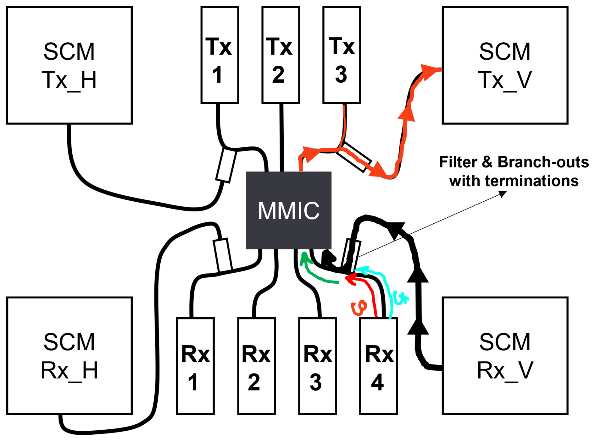
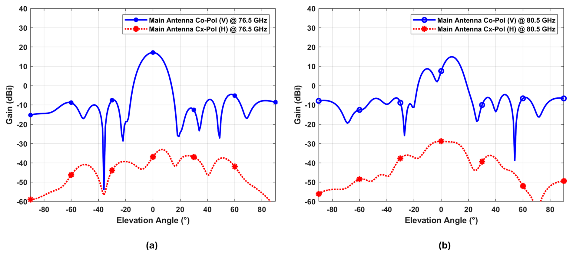
Figure 11Main antenna's elevation cuts: (a) Co and cross-pol elevation cuts at 76.5 GHz, (b) Co and cross-pol elevation cuts at 80.5 GHz.
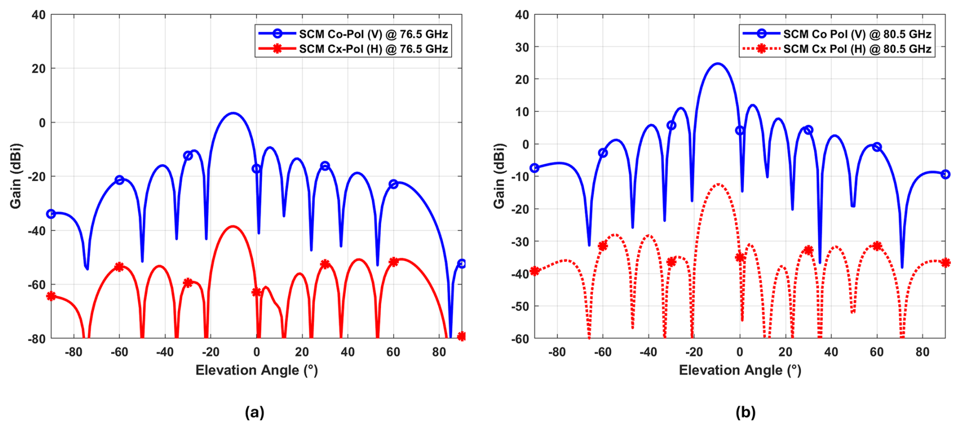
Figure 12SCM antenna's elevation cuts: (a) Co and cross-pol elevation cuts at 76.5 GHz, (b) Co and cross-pol elevation cuts at 80.5 GHz.
4.4.2 Simulation Results
The performance of the antennas are characterized by their elevation gain patterns at both 76.5 and 80.5 GHz. Figures 11 and 12 presents the elevation gain patterns for the radar sensor's main antennas and SCM antennas at mentioned frequencies. These patterns are used in the simulations and are crucial for understanding the mutual influence between the antennas during signal transmission and reception. Simulation results are presented to quantify the mutual influence between the main and SCM antennas at their respective frequency bands as following:
-
At 80.5 GHz: The SCM antennas are active for street condition monitoring, for example when SCM Tx-V is radiating a negligible amount of power is also radiated from the sensor's main antenna Tx3. The SCM receiver (RX-V) dominantly receives the signal, a small amount of signal is also received by the main antenna (Rx4) of the radar receiver as shown in Fig. 13. The impact of this leakage on the noise level is evaluated, with results showing an additional noise contribution of approximately 0.01 dB, as shown in Fig. 14.
-
At 76.5 GHz: The main antennas of radar sensor are operational, and ideally, there should be no disturbance from the SCM antennas. However, due to channel-sharing, a small amount of power is coupled to the SCM antennas as shown in Fig. 15. The simulation results indicate that this coupled power contributes up to 1.47 dB of additive noise to the main radar signal in the very near range (up to 3 m), as shown in Fig. 16.
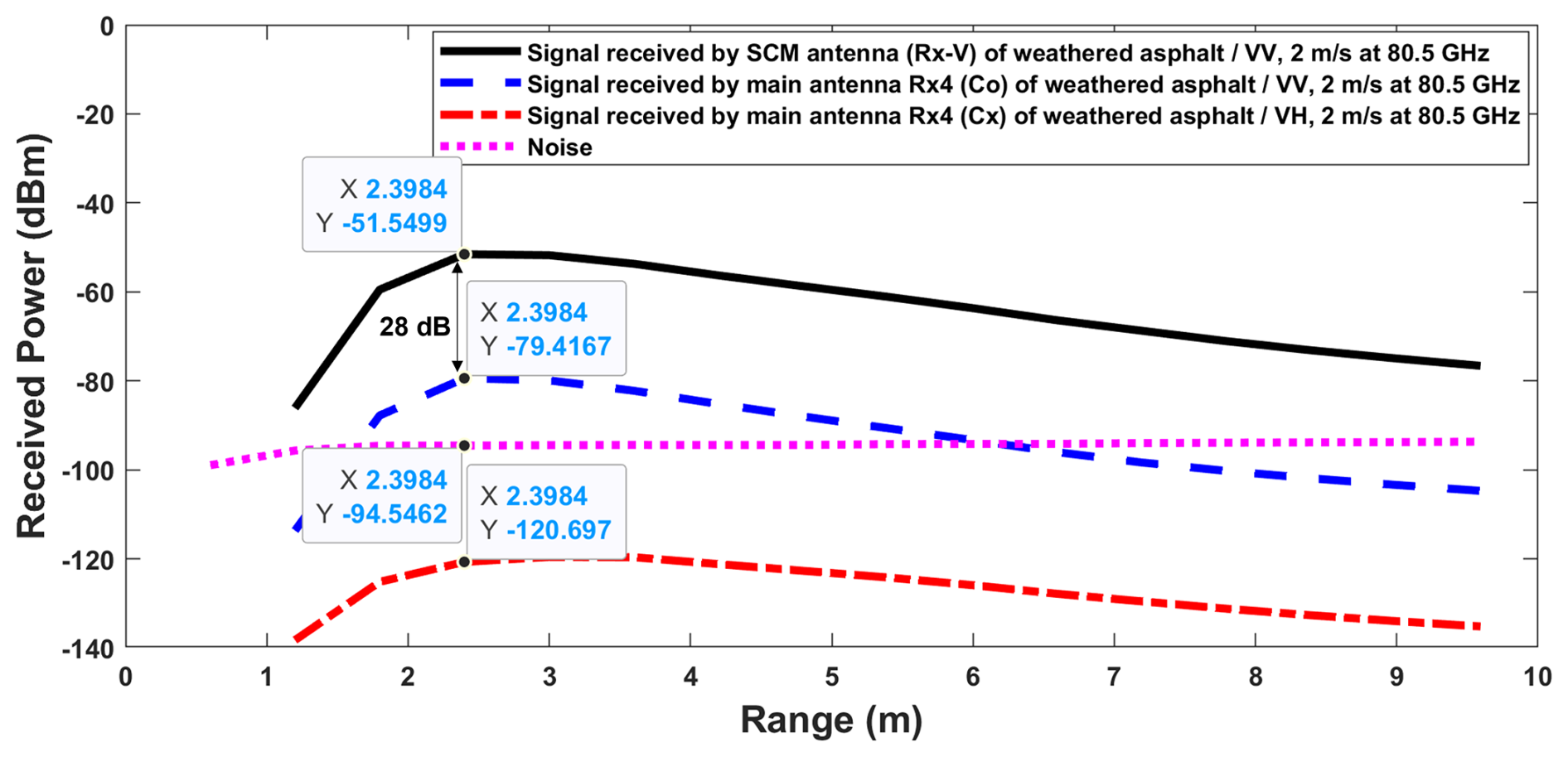
Figure 13Absolute street reception (1 range bin, ego Doppler bin) for SCM V-Pol transmit and V-Pol receive configuration at 80.5 GHz.
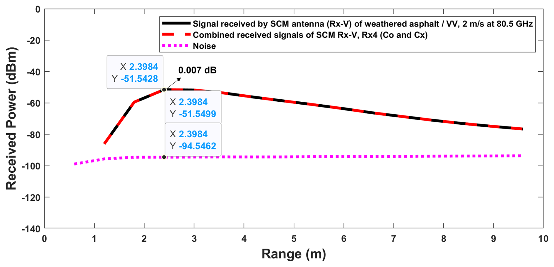
Figure 14Absolute street reception (1 range bin, ego Doppler bin) for SCM V-Pol transmit and V-Pol receive configuration at 80.5 GHz.
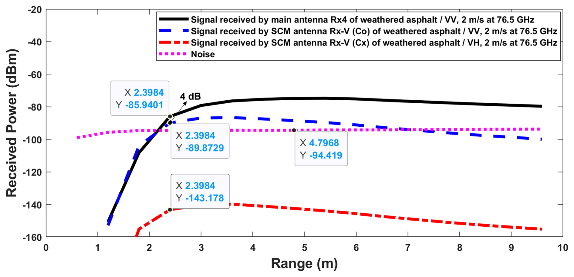
Figure 15Absolute street reception (1 range bin, ego Doppler bin) for SCM V-Pol transmit and V-Pol receive configuration at 76.5 GHz.
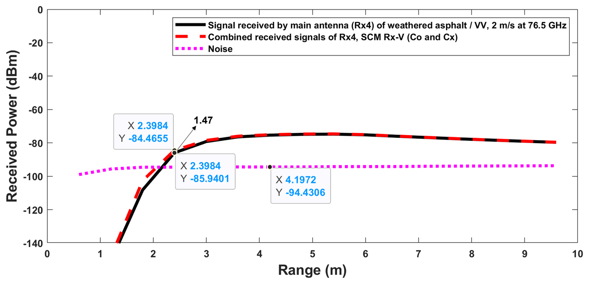
Figure 16Absolute street reception (1 range bin, ego Doppler bin) for SCM V-Pol transmit and V-Pol receive configuration at 76.5 GHz.
4.4.3 Results Discussion
The results demonstrate the following:
-
Impact on SCM Antennas: At 80.5 GHz, the influence of the radar sensor's main antennas on SCM antennas is negligible due to the effective power isolation achieved by the filter. The additional noise contribution of 0.01 dB is minimal and does not impact the SCM antenna's performance significantly.
-
Impact on Main Antennas: At 76.5 GHz, the SCM antennas introduces a minor effect on the main antennas of the radar sensor, noticeably in the near range around 1.5 to 2.5 m. This results in an additive noise of approximately 1.47 dB. However, it's important to note that this has minimal impact on the main antenna's performance, particularly since the radar sensor is typically used for mid- to long-range applications beyond this range.
-
Design Implications: These findings emphasizes on importance of antenna isolation, the need for careful antenna design and placement, particularly in channel-sharing configurations, to minimize mutual coupling. Ensuring sufficient isolation is critical for preserving the performance of both the main antennas and the SCM antennas of the radar sensor.
4.5 On-Chip Channel Isolation
The selection of the MMIC chip is critical for ensuring optimal system performance. Automotive radar MMICs typically achieve TX to RX isolation levels of 30 to 40 dB. For example, as demonstrated in Tanaka et al. (2002), a 76–77 GHz GaAs PIN-diode-switch MMIC for automotive radar applications provides an isolation exceeding 32 dB, with an insertion loss below 2 dB. Such isolation is very important to minimize signal coupling between channels, which can significantly degrade system performance. To further improve isolation, SCM transmitters and receivers should be connected to non-adjacent channels. Maintaining sufficient spacing reduces crosstalk and mutual coupling, thereby enhancing overall system isolation. Additional isolation can also be achieved through phase coding techniques. While simultaneous activation of transmitters with distinct phase codes improves isolation, alternating activation provides the highest isolation performance.
This study has presented, for the first time to our knowledge, a frequency-selective dual linearly polarized automotive radar system concept capable of detecting a wide range of street types and conditions without significant degradation of standard MIMO radar performance. Three key aspects were addressed: the frequency-selective system approach, antenna design for street condition monitoring (SCM), and the minimum co-to-cross-polarization isolation required for reliable dual-frequency operation. By using a step-impedance filter (SIF) to share MMIC channels between SCM at 80.5 GHz and standard radar operation at 76.5 GHz, the system achieves cross-polarization isolation above 37 dB and minimal mutual coupling, preserving both power and phase characteristics critical for angular measurement accuracy in automotive applications. Having previously validated SCM performance using dedicated MMIC channels, the next step is to realize the same capability with the proposed shared-channel SIF approach. This will involve fabricating the integrated antenna/filter design, conducting laboratory and on-vehicle measurements across diverse surfaces and conditions, and evaluating classification performance in both radar modes. The resulting datasets will support the development of advanced classification algorithms, including machine learning, to further improve accuracy, with the ultimate goal of delivering a compact, production-ready system for real-time street type and condition monitoring in autonomous and assisted driving platforms.
The MATLAB-based simulation framework used in this study was jointly developed by Aptiv Services Deutschland GmbH and Technische Universität Chemnitz and cannot be publicly shared due to confidentiality agreements. The full theoretical model, governing equations, and key simulation parameters are documented in our previous publications (Kazimi et al., 2024a, b, 2025), which provide sufficient detail to reproduce the described analyses.
The simulation data used in this study were generated using a joint Aptiv–TU Chemnitz framework and are subject to confidentiality agreements. All parameters and equations needed to reproduce the results are provided in this paper and the referenced works (Kazimi et al., 2024a, b, 2025).
SHK developed the system proof-of-concept, including system development, defining key performance indicators, formulating antenna design requirements, developing the system simulation tool in MATLAB to evaluate the performance of the designed antennas and overall system functionality and wrote the manuscript. The antenna was initially designed by SR using Empire, with further modifications by WAS. DV and MC provided supervision, revisions, and guidance throughout the research and manuscript preparation.
At least one of the (co-)authors is a member of the editorial board of Advances in Radio Science. The peer-review process was guided by an independent editor, and the authors also have no other competing interests to declare.
Publisher’s note: Copernicus Publications remains neutral with regard to jurisdictional claims made in the text, published maps, institutional affiliations, or any other geographical representation in this paper. While Copernicus Publications makes every effort to include appropriate place names, the final responsibility lies with the authors. Views expressed in the text are those of the authors and do not necessarily reflect the views of the publisher.
This article is part of the special issue “Kleinheubacher Berichte 2024”. It is a result of the Kleinheubacher Tagung 2024, Miltenberg, Germany, 24–26 September 2024.
This work was supported by a research grant provided by TU Chemnitz in collaboration with Aptiv Services Deutschland GmbH.
This work was supported by a research grant provided by TU Chemnitz in collaboration with Aptiv Services Deutschland GmbH.
This paper was edited by Andreas Danklmayer and reviewed by two anonymous referees.
Elliott, R.: On the design of traveling-wave-fed longitudinal shunt slot arrays, IEEE Transactions on Antennas and Propagation, 27, 717–720, 1979. a, b
Gatesman, A., Goyette, T., Dickinson, J., Giles, R., Waldman, J., Sizemore, J., Chase, R., and Nixon, W.: Polarimetric backscattering behavior of ground clutter at X, Ka, and W-band, in: Algorithms for Synthetic Aperture Radar Imagery XII, SPIE, 5808, 428–439, 2005. a
Giallorenzo, M., Cai, X., Nashashibi, A., and Sarabandi, K.: Radar backscatter measurements of road surfaces at 77 GHz, in: 2018 IEEE International Symposium on Antennas and Propagation & USNC/URSI National Radio Science Meeting, IEEE, 2421–2422, https://doi.org/10.1109/APUSNCURSINRSM.2018.8609191, 2018. a, b
Hosseininejad, S. E. and Komjani, N.: Optimum design of traveling-wave SIW slot array antennas, IEEE transactions on antennas and propagation, 61, 1971–1975, 2012. a
Kazimi, S. H., Sanka, S., Cai, X., Vollbracht, D., and Chandra, M.: Street Condition Monitoring with Automotive Dual Linearly Polarized Radar System: Measurement Results and Classification, in: 2024 Kleinheubach Conference, Miltenberg, Germany, 24–26 Sep 2024, IEEE, 1–4, https://doi.org/10.23919/IEEECONF64570.2024.10739134, 2024a. a, b
Kazimi, S. H., Vollbracht, D., Varma, S., and Chandra, M.: Dual linearly polarized 76–81 ghz automotive antenna system concept for street condition monitoring, in: 2024 Kleinheubach Conference, Miltenberg, Germany, 24–26 Sep 2024, IEEE, 1–4, https://doi.org/10.23919/IEEECONF64570.2024.10739226, 2024b. a, b, c, d
Kazimi, S. H., Vollbracht, D., and Chandra, M.: A Theoretical Analysis of Polarimetric Street Condition Monitoring System Concepts to Enhance Detection Range at 76–81 GHz, in: 2025 26th International Radar Symposium (IRS), Hamburg, Germany, 21–23 May 2025, IEEE, 1–6, https://doi.org/10.23919/IRS64527.2025.11046113, 2025. a
Li, E. S. and Sarabandi, K.: Low grazing incidence millimeter-wave scattering models and measurements for various road surfaces, IEEE Transactions on Antennas and Propagation, 47, 851–861, 1999. a
Sarabandi, K., Li, E. S., and Nashashibi, A.: Modeling and measurements of scattering from road surfaces at millimeter-wave frequencies, IEEE Transactions on Antennas and Propagation, 45, 1679–1688, 1997. a
Tanaka, Y., Uda, H., Hayashi, H., Ueda, H., and Usui, M.: A 76–77 GHz high isolation GaAs PIN-diode switch MMIC, R&D Review of Toyota CRDL, 37, 19–26, 2002. a
Trummer, S., Hamberger, G. F., Koerber, R., Siart, U., and Eibert, T. F.: Autonomous driving features based on 79 GHz polarimetric radar data, in: 2018 15th European Radar Conference (EuRAD), Madrid, Spain, 26–28 Sep 2018, IEEE, 18–21, https://doi.org/10.23919/EuRAD.2018.8546632, 2018. a
Viikari, V., Varpula, T., and Kantanen, M.: Automotive radar technology for detecting road conditions. Backscattering properties of dry, wet, and icy asphalt, in: 2008 European Radar Conference, IEEE, Amsterdam, Netherlands, 276–279, ISBN 978-2-87487-009-5, 2008. a
Vollbracht, D. and Varma, S.: Radar Antenna System, U.S. Patent Application US 2024/0329192 A1, Aptiv Technologies AG, Schaffhausen (CH), 2024. a, b, c
Vollbracht, D., Kazimi, S. H., and Varma, S.: Radar System for Automotive Applications, U.S. Patent Application US 2024/0012097 A1, Aptiv Technologies Limited, St. Michael (BB), filed 30 June 2023, 2024. a