 | 19 Sep 2019
Extending the vehicular network simulator Artery in order to generate synthetic data for collective perception
Christoph Allig
Gerd Wanielik
A fundamental for an automated driving car is the awareness of all its surrounding road participants. Current approach to gather this awareness is to sense the environment by on-board sensors. In the future, Vehicle-to-X (V2X) might be able to improve the awareness due to V2X's communication range superiority compared to the on-board sensors' range. Due to a limited amount of communication partners sharing their own ego states, current research focuses particularly on cooperative perception. This means sharing objects perceived by local on-board sensors of different partners via V2X. Data collections using vehicles, driving on real roads, is challenging, since there is no market introduction of cooperative perception yet. Using test cars, equipped with the required sensors are rather expensive and do not necessarily provide results representing the true potential of cooperative perception. Particularly, its potential is highly dependent on the market penetration rate and the amount of vehicles within certain vicinity. Therefore, we consider to create synthetic data for cooperative perception by a simulation tool. After reviewing suitable simulation tools, we present an extension of Artery and its counterpart SUMO by modelling realistic vehicle dynamics and probabilistic sensor models. The generated data can be used as input for cooperative perception.
- Article
(1994 KB) - Full-text XML
- BibTeX
- EndNote


Today's Advanced Driver Assistance Systems (ADASs) rely on on-board sensors, which perceive other road participants and obstacles within their Field-of-View (FOV). The perception system fuses measurements from all of the on-board sensors, such as camera and radar, and generates an environmental model. Due to limited FOVs, the perception system is not able to provide a complete environmental model. On-board sensors like camera or radar are limited in their perception range and due to possible occlusions. Additionally, in unfavourable weather conditions the perception system might fail. However, for automated driving of level 3 and higher, a best possible perception of the environment is required in order to understand the scene adequately and to make the right decision. In order to resolve these issues, Vehicle-to-X (V2X) communication might be a key technology. The communication range is significantly higher than the sensors' perception range and V2X communication is robust to occlusions and weather conditions. In the first few years after market launch of V2X communication, the ratio of V2X enabled road participants will be limited. Additionally, there might always be non-connected road participants, e.g. pedestrians or cyclists not carrying any mobile phone. Therefore, only a certain ratio of road participants are able to broadcast ego state information, why current research focuses particularly on cooperative perception. This means sharing objects perceived by local on-board sensors of different partners via V2X. For the development of cooperative perception, simulation tools generating synthetic data are a reasonable complement to data collections. In this paper, we extend an open-source simulation tool such that it is able to generate synthetic data that can be used to develop cooperative perception applications. Firstly, we review in Sect. 2 simulation tools for cooperative automated driving (CAD). We have selected Artery as simulation tool, which extends the Vehicles in Network Simulation (Veins) by an implementation of the European Telecommunications Standards Institute Intelligent Transport Systems (ETSI ITS)-G5 protocol (ETSI, 2019) and a local perception toolbox. Veins couples the traffic simulator Simulation of Urban Mobility (SUMO) with the network-simulator OMNeT++. In Sect. 3 our extensions to SUMO are described in order to model realistic vehicle dynamics. Modifications to Artery are described in Sect. 4. This includes probabilistic sensor models, sensor fusion algorithms and a service for disseminating and receiving Cooperative Perception Messages (CPMs). In Sect. 5 an evaluation of the vehicle dynamics described in Sect. 3 is presented.
A simulation tool for CAD must provide sufficient realistic network communication models and sufficient realistic vehicle movements and sufficient realistic sensors, while achieving simultaneously sufficient scalability. The specifications sufficient realism and sufficient scalability are contradictory and result in a trade-off. The choice in favour of the realism or the scalability depends on the desired application. For example, if the application focuses on investigating characteristics of the network of Inter-Vehicle Communication (IVC), scalability and network communication models are in favour and realistic vehicle models might be ignored. Whereas, if the application aims at cooperative manoeuvring or evaluating tracking performance of cooperative perception, realism is in favour and requires to model e.g. the powertrain, lateral vehicle dynamics and distinct probabilistic sensors. A standalone simulation tool for CAD is not available to date. However, for simulating network models and vehicles there are various network, respectively traffic simulators available. A well-known option for CAD simulations is the bidirectional coupling of simulators, like coupling a traffic simulator and a network simulator. The simulators run in parallel and exchange data among them. Subsequently, we list non-exhaustively relevant simulators and coupling approaches.
Traffic simulators are distinguishable by the applied model, respectively the simulation's level of detail. There are macro-, meso-, micro- and submicroscopic modelling approaches. Macro- and mesoscopic models are listed only for the sake of completeness, but are not of relevance for CAD simulations. Macroscopic simulators model roads as smallest entity characterised by e.g. density or mean speed. Mesoscopic simulators model partitioned roads or a convoy of vehicles and represent an intermediate level in between macro- and microscopic simulators. Microscopic simulators model the movement of each vehicle by vehicle-following. VISSIM (PTV Planung Transport Verkehr AG, 2018) and its open-source counterpart SUMO (Krajzewicz et al., 2002) are popular representatives. Submicroscopic simulators extend microscopic models by additionally modelling specific parts of the vehicle, e.g. power train, vehicle dynamics or sensors. Submicroscopic traffic simulators are also often called, nanoscopic traffic simulator, or driving simulator and often included in robotics simulators. A non-exhaustive list of representatives for submicrosopic simulators: SiVIC (Gruyer et al., 2014), PreScan (International TASS, 2018), TORCS (Wymann et al., 2015), RACER (Gonzalez and Kalyakin, 2009), VDrift (Kehrle et al., 2011), Webots (Michel, 2004) and PHABMACS (Massow and Radusch, 2018).
The most popular network simulators for CAD are OMNeT++ (OMNeT++, 2018) and ns-3 (ns-3, 2018).
Subsequently, different frameworks that enable the bidirectional coupling of traffic and network simulators are listed. Rondinone et al. (2013) presents the open-source simulation platform iTetris that integrates the traffic simulation SUMO and the network simulation ns-3. Llatser et al. (2017) couples the commercial submicroscopic vehicle simulator Webots and the network simulator ns-3, which achieves an high realism in vehicle dynamics. In Gomez et al. (2014) the submicroscopic traffic simulator MORSE and the network simulator ns-3 are coupled and applied for cooperative adaptive cruise control (CACC). Schünemann (2011) proposes VimSIMRTI, which allows flexible coupling of different network and traffic simulators, e.g. ns-3, OMNet++ and VSimRTI cellular, respectively SUMO and PHABMACS. The open-source tool Veins (Sommer et al., 2011) provides simulation modules for vehicular networking. It executes two simulators in parallel: OMNeT++ for network simulations and SUMO for traffic simulations. Both simulators are connected by the Traffic Control Interface (TraCI).
In recent research, there is also the trend for a coupled micro- and submicroscopic traffic simulation. Pereira and Rossetti (2012) couples the microscopic traffic simulator SUMO and the submicroscopic traffic simulator USARSim. Also in Barthauer and Hafner (2018), a micro- and submicroscopic traffic simulator are bidirectionally coupled, namely SUMO and SILAB. Aramrattana et al. (2017) presents a simulation framework consisting of the VTI's driving simulator, the traffic Simulator Plexe-SUMO and the network simulator Plexe-VEINS. This framework is applied for testing and evaluation of CACC. Plexe (Segata et al., 2015) is an open source extension to VEINS and permits the simulation of CACC or platooning systems. Communication protocols for platooning are realized in VEINS, while distinct cruise controllers and engine dynamics are implemented in SUMO. Schiller et al. (2015) proposes an approach for coupling traffic simulators (SUMO and VIRES Virtual Test Drive) of different resolutions to satisfy the constraints of performing simulations in real time.
In this work, we use the simulation framework Artery (Riebl et al., 2015), which extends Veins by an implementation of the ETSI ITS-G5 network and transport protocols, called Vanetza. Additionally, each vehicle is individually configurable regarding its capabilities of ITS-G5 services. For example, Artery includes a ITS-G5 service for disseminating Cooperative Awareness Messages (CAMs). In Günther et al. (2015), Artery is extended by a local perception toolbox, which allows for the introduction of individual local perception sensors for each vehicle. The framework has been used so far for investigating the network performance and to compare the awareness ratio between on-board sensors and CAMs (Günther et al., 2016, 2018).
As already mentioned, SUMO is a microscopic traffic simulator and thus does not include any vehicle model. The consequences are instantaneous accelerations or instantaneous and unbounded yaw rates. This is impractical as a simulation tool used for development or evaluation of cooperative perception. In Segata et al. (2015), longitudinal vehicle dynamics have already been added to SUMO. We further extend this approach by modelling additionally lateral vehicle dynamics.
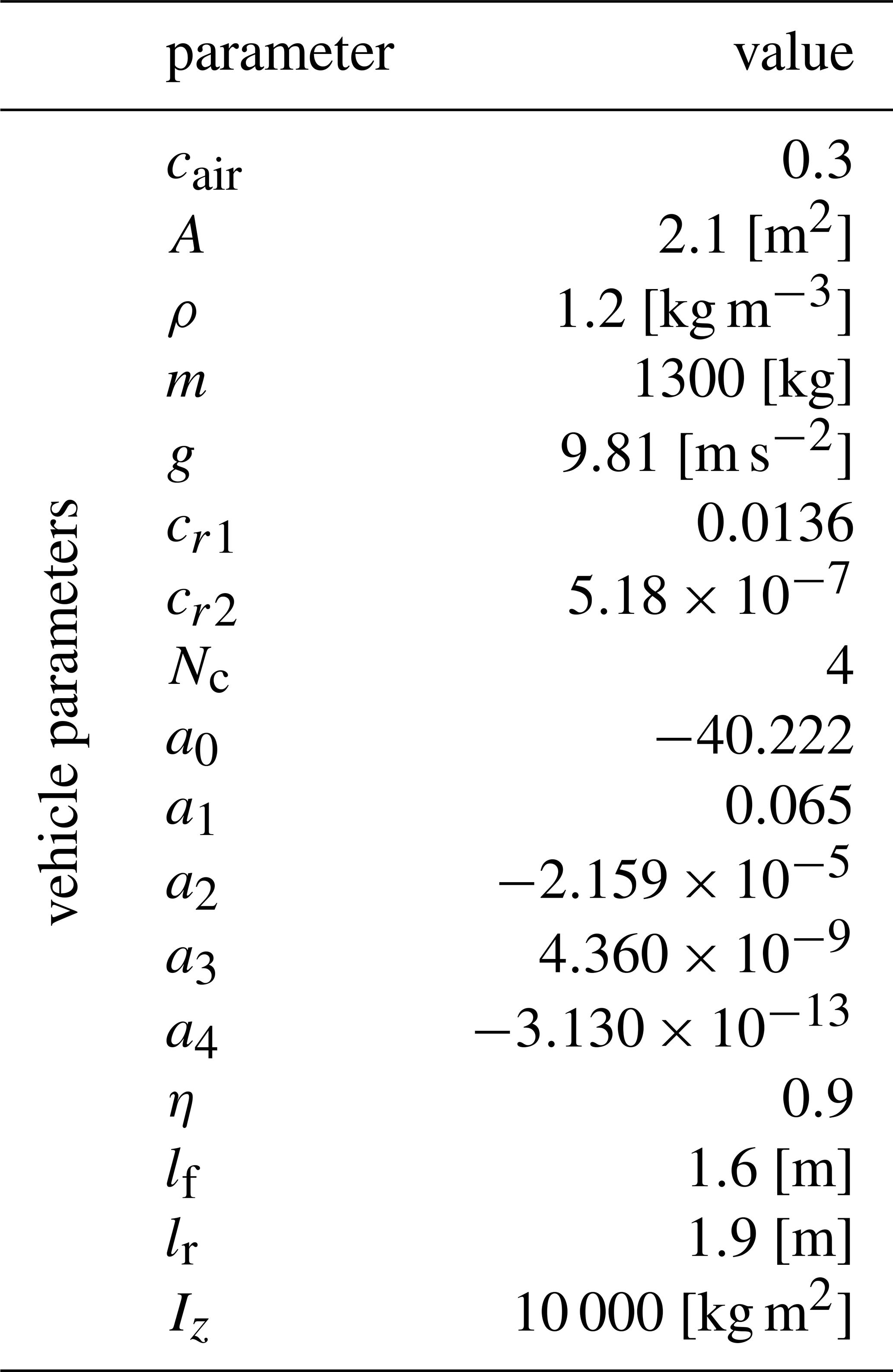
Subsequently, the modifications to SUMO are described. Section 3.1 describes the longitudinal vehicle dynamics, while Sect. 3.2 describes the lateral vehicle dynamics. Further theoretical background on vehicle dynamics can e.g. be found in Rajamani (2006). The vehicle parameters applied in the longitudinal and lateral models are summarized in Table 1. In Sect. 3.3, the Pure Pursuit algorithm is presented, which is used to keep the vehicle centred in its current lane.
3.1 Longitudinal vehicle dynamics
The longitudinal acceleration of a vehicle is dependent on the mass of the vehicle m and the sum of the forces acting in longitudinal direction on the vehicle:
where FA, FR and FG are the air resistance, the rolling resistance, respectively the gravitational force:
where cair is the aerodynamic drag coefficient, ρ is the density of air and A is the cross-sectional area of the vehicle. The parameters cr1 and cr2 are dependent on the tires and their pressure. The gravitational acceleration and the inclination of the road are denoted as g, respectively θroad. The acceleration force Fx is dependent on the desired acceleration , which is determined in a longitudinal control system. However, the desired acceleration is not immediately the true acceleration of the vehicle. Indeed, there is an actuation lag due to communication delays between distinct controllers and the physical process until the force is transmitted to the tires and accelerates the vehicle. This actuation lag is modelled using a first order lag:
The parameter α depends on the simulation sampling time Δt and the actuation lag τ:
Opening the fuel valves and injecting the fuel is modelled by the parameter τinj(n), while burning the fuel and accelerating the crankshaft is considered by the parameter τburn(n):
Additionally, a constant transport delay τexh of 100 ms is considered. Nc is the number of cylinders and n is the engine speed expressed in [rps]. The maximum engine force depends on the the engine power Peng, which again is dependent on the current engine speed Neng in [rpm]:
where η denotes the engine efficiency and is the speed in [m s−1]. Engine power curves can be found e.g. at Automobile-Catalog (2019). We model the engine power using a polynomial function:
So far, we only considered forces in case of positive acceleration, where the acceleration force is Fx=Feng. On the other hand, if the vehicle is braking, the acceleration force Fx is negative. The maximum braking force is . The braking actuation lag is fixed to τ=200 ms.
3.2 Lateral vehicle dynamics
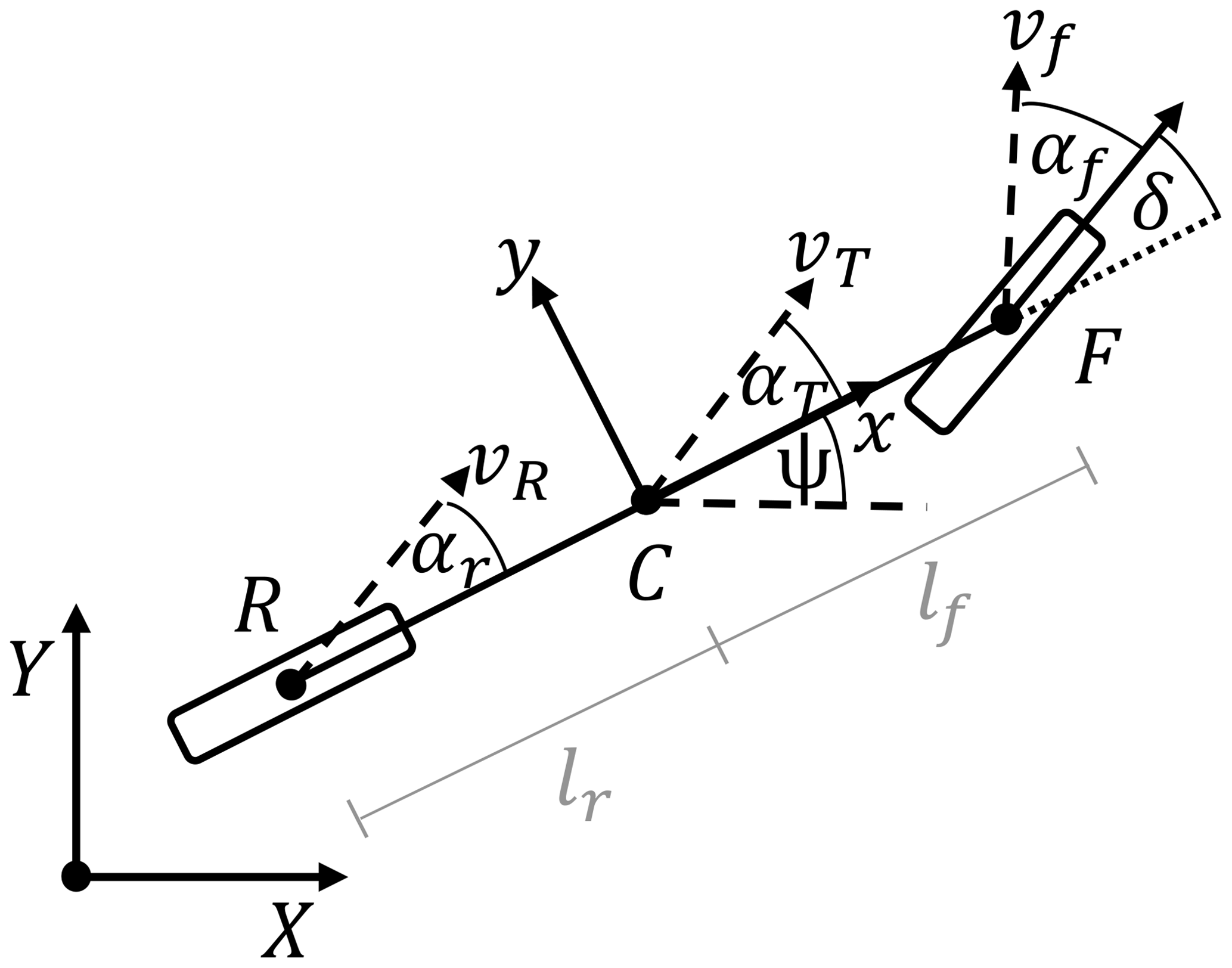
For modelling the lateral vehicle dynamics, the dynamic bicycle model as shown in Fig. 1 is applied. The distances of the front axle F and the rear axle R to the center of the vehicle C are denoted as lf, respectively lr. The yaw angle ψ defines the orientation of the vehicle's body frame with regard to the global frame. The side slip angle αt and the yaw angle define together the driving direction of the vehicle with velocity vt. The direction of the velocity vf at the front axle is dependent on the front slip angle αf and the steering wheel angle δ. The rear slip angle αr determines the direction of the velocity vr at the rear axle.
Using again Newton's second law, the lateral acceleration is dependent on the mass of the vehicle and the sum of the forces acting in lateral direction on the vehicle:
where and are the lateral tire forces of the front and rear wheels, respectively. The inertial lateral acceleration ay comprises two terms, the acceleration along the y-axis and the centripetal acceleration . The angular acceleration is dependent on the moment of inertia Iz, the lateral tire forces and the the distances of the front lf and rear lr tire to the center of the vehicle:
The tire forces are due to deformations which occur during manoeuvring. These deformations result in a slip angle α and vice versa the tire forces can be expressed as a non-linear function depending on the slip angle. The slip angle of the front wheel αf and the real wheel αr can be determined by:
To model the front and rear tire forces, the well-known Pacejka tire model is applied. The generated force can be expressed as a function of the slip angle α:
where
Fy might be the front lateral tire force or the rear lateral tire force and α the front slip angle αf or the rear slip angle αr. For further information on the model parameters B, C, D, E, Sh and Sv, see e.g. Rajamani (2006).
Rewriting Eqs. (10) and (11) results in the lateral acceleration and the angular acceleration:

In order to be able to model the previously described lateral vehicle dynamics in SUMO, it is required to detach the vehicle from its lane and that the vehicle is able to move freely through the cartesian space. As shown in Fig. 2, in SUMO the vehicle's movement is usually described by a position on lane value. The vehicle is always driving on the center of lane, wherefore the lateral offset equals zero. A global cartesian position might be calculated by a function that uses additionally the start and end position of the present lane. We determine the vehicle's movement in the global frame and update always the redundant values that describe the longitudinal and lateral position on the current lane. The steering wheel angle δ is the input parameter of the lateral vehicle dynamics. The steering wheel angle is controlled by the path tracking algorithm that is described in the next subsection.
3.3 Path tracking
For path tracking we apply the Pure Pursuit controller, which is a popular geometric controller that determines the desired steering wheel angle δ according to:
It's basic principle is to follow a carrot-point, that is defined based on the look-ahead distance ld and the planed trajectory. In our case corresponds the planed trajectory to the center of lane. The angle θ is given through the velocity vector of the vehicle and the look-ahead vector. The parameter L corresponds to the wheelbase of the vehicle.
We start with a brief review of the local perception toolbox of Artery (Günther et al., 2015), which is shown in Fig. 3. The local perception toolbox of Artery is based on the Global Environmental Model (GEM), the Local Environmental Model (LEM) and the local perception sensors.
The GEM acts as a global database containing all vehicles within the simulation. Each vehicle is described by a Global Environmental Object (GEMO). The GEMO retrieves continuously values of the corresponding vehicle in SUMO via TraCI. Each vehicle might be equipped with local perception sensors. Those sensors are configurable by the perception range, the opening angle as well as the mounting point on the vehicle. The GEM provides functionality to determine if other vehicles are perceived by the installed sensors.
Every vehicle equipped with a sensor creates its own instance of a LEM. The LEM acts as the database of all vehicles that are perceived by the ego vehicle. Whenever a measurement is performed by the sensor, the vehicles within its perception range, respectively their corresponding Local Environmental Model Objects (LEMOs) are updated. Whenever a vehicle is first measured by a perception sensor, i.e. the vehicle has not be sensed before by the ego vehicle, a new LEMO is created for that particular vehicle. In Günther et al. (2015), there is one LEMO per sensor per perceived object. The LEMO stores the last measurements. Whereas, in our approach, a LEMO comprises one object tracker processing the measurements of all perception sensors installed in the ego vehicle. In Sect. 4.1 a probabilistic radar and camera model are described. In Sect. 4.2 we describe the operating principle of the involved modules in cooperative perception.
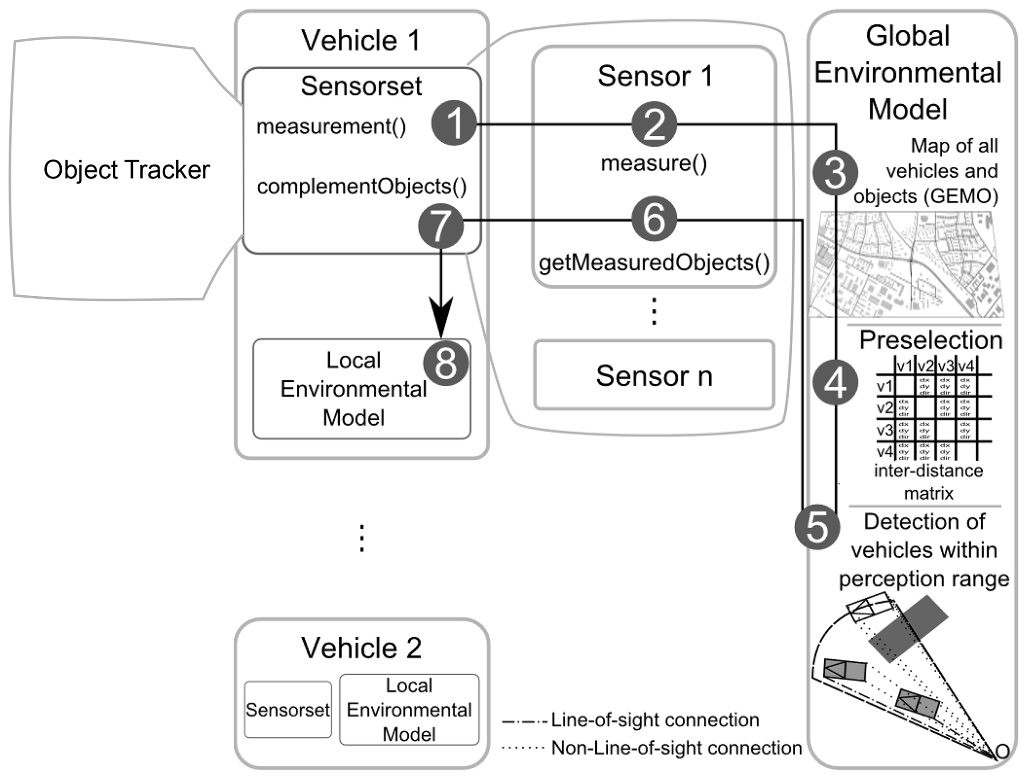
Figure 3Artery's local perception toolbox (Günther et al., 2015).
4.1 Sensor modelling
We extend Artery by a probabilistic radar and camera sensor model. The radar sensor measures target range r, azimuth angle θ and range rate with frequency f=10 Hz:
The respective measurement noise is described by wr, wθ and , which are zero mean white Gaussian noises with standard deviations σr=1.2 m, σθ=0.01 rad and m s−1. The camera sensor measures the position in picture coordinates u and v with the same frequency:
Here the respective measurement noise is given by wu and wv, which are zero mean white Gaussian noises with standard deviations σu=6 and σv=6 pixels. The variables qij correspond to the elements of the projection matrix. The global position of the detected vehicle and the ego vehicle are given by xo and yo, respectively by xe and ye. The detected vehicle drives with velocity v towards the direction ϕo. The sensor models and its parameters have been taken over from the data fusion software BASELABS Create (BASELABS, 2019).
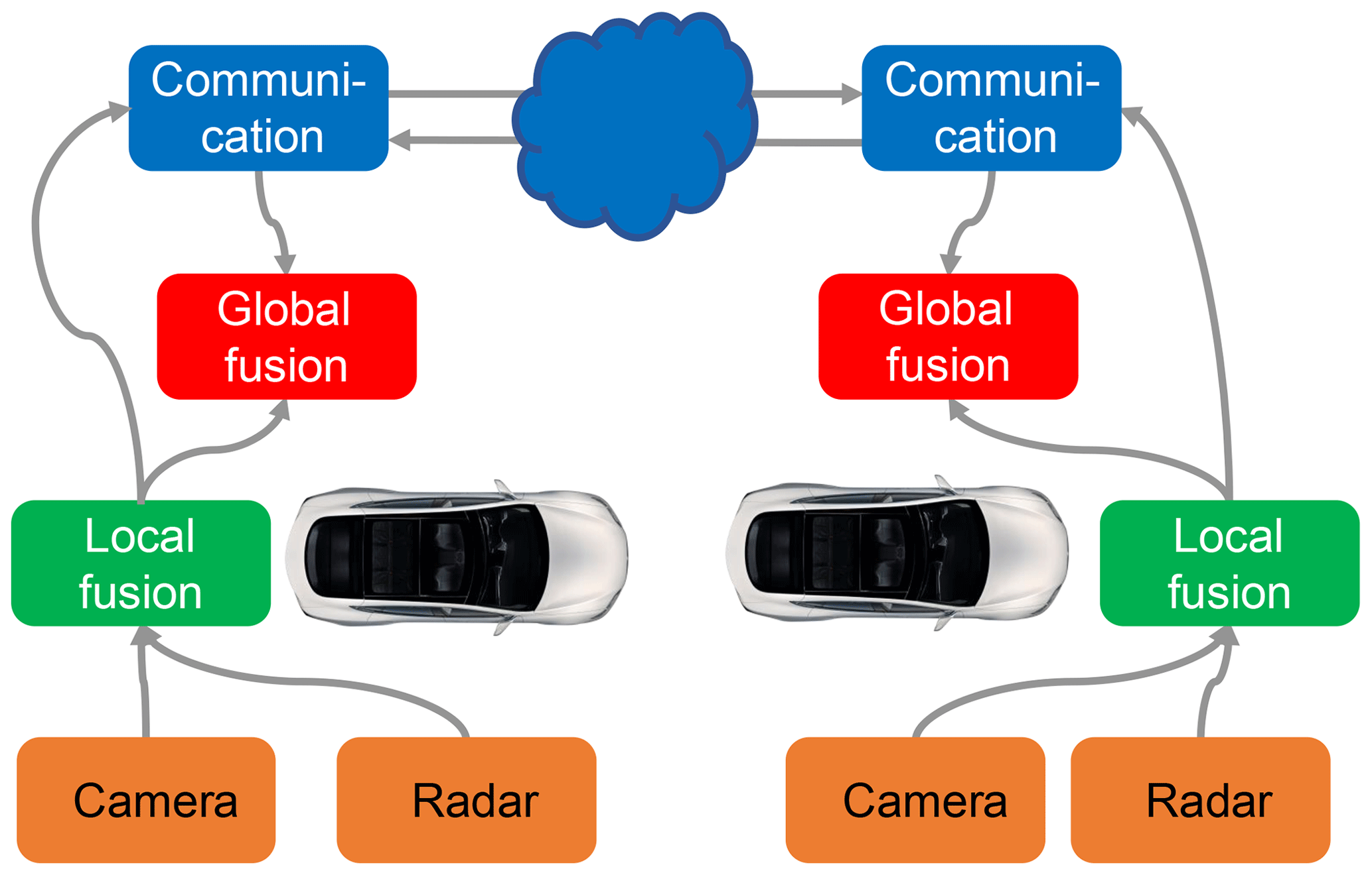
4.2 Cooperative perception
The implemented architecture of the cooperative perception is shown in Fig. 4. The in Sect. 4.1 described sensors generate noisy measurements which are fused in the respective local fusion module. The result of the local fusion module is broadcasted via V2X communication. The information received by the communication module is then fused into the global fusion module with the result of the local fusion module.
Whenever a LEMO is updated, its corresponding local fusion is triggered, i.e. there are multiple single object tracker. The object tracker firstly compensates the ego motion. Secondly, the track is predicted using the Unscented Kalman Filter (UKF) according to the system model. Depending on the sensor that has triggered the local fusion, a noisy measurement is generated. Finally, the track is updated by the UKF using the corresponding measurement model. A CPM service is implemented that creates a CPM message containing information about the ego state, the FOVs of the local sensors and the tracked objects. The ego state information is interpretable as a downsized CAM and describes the dynamic state of the broadcasting vehicle. It is provided by Artery's GEMO. The tracked object states are obtained by an access to the LEMOs' local fusion module.
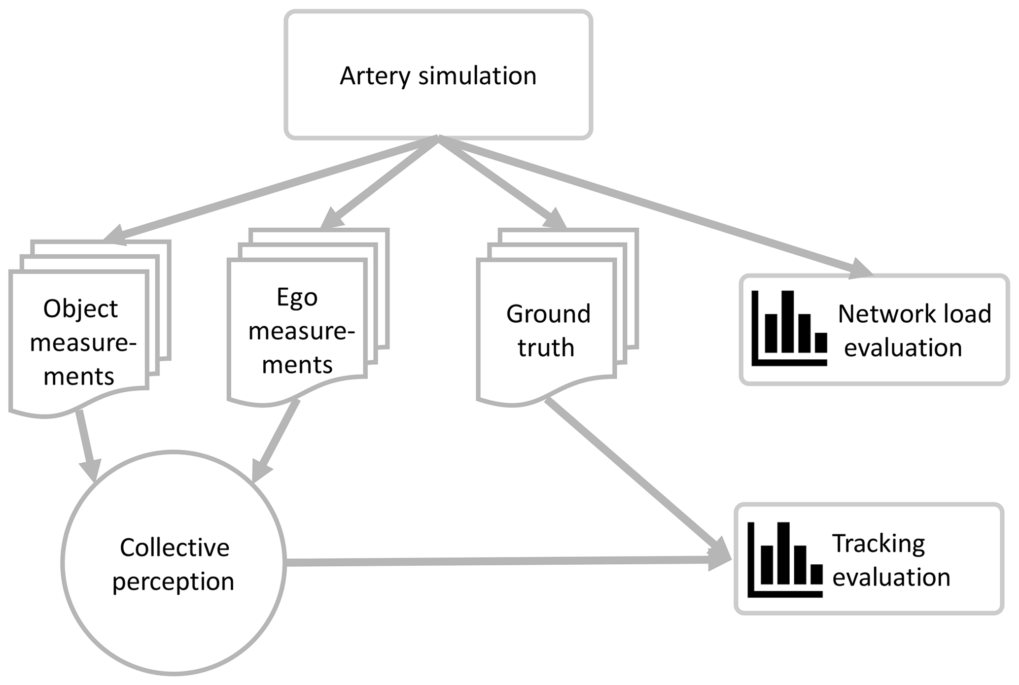
Artery with its extensions described so far is used to evaluate the network load. Additionally, Artery outputs the ground truth and non-noisy measurements that might be used for Monte-Carlo simulations, i.e. the noise is added later in a separate fusion framework. Both opportunities are shown in Fig. 5.
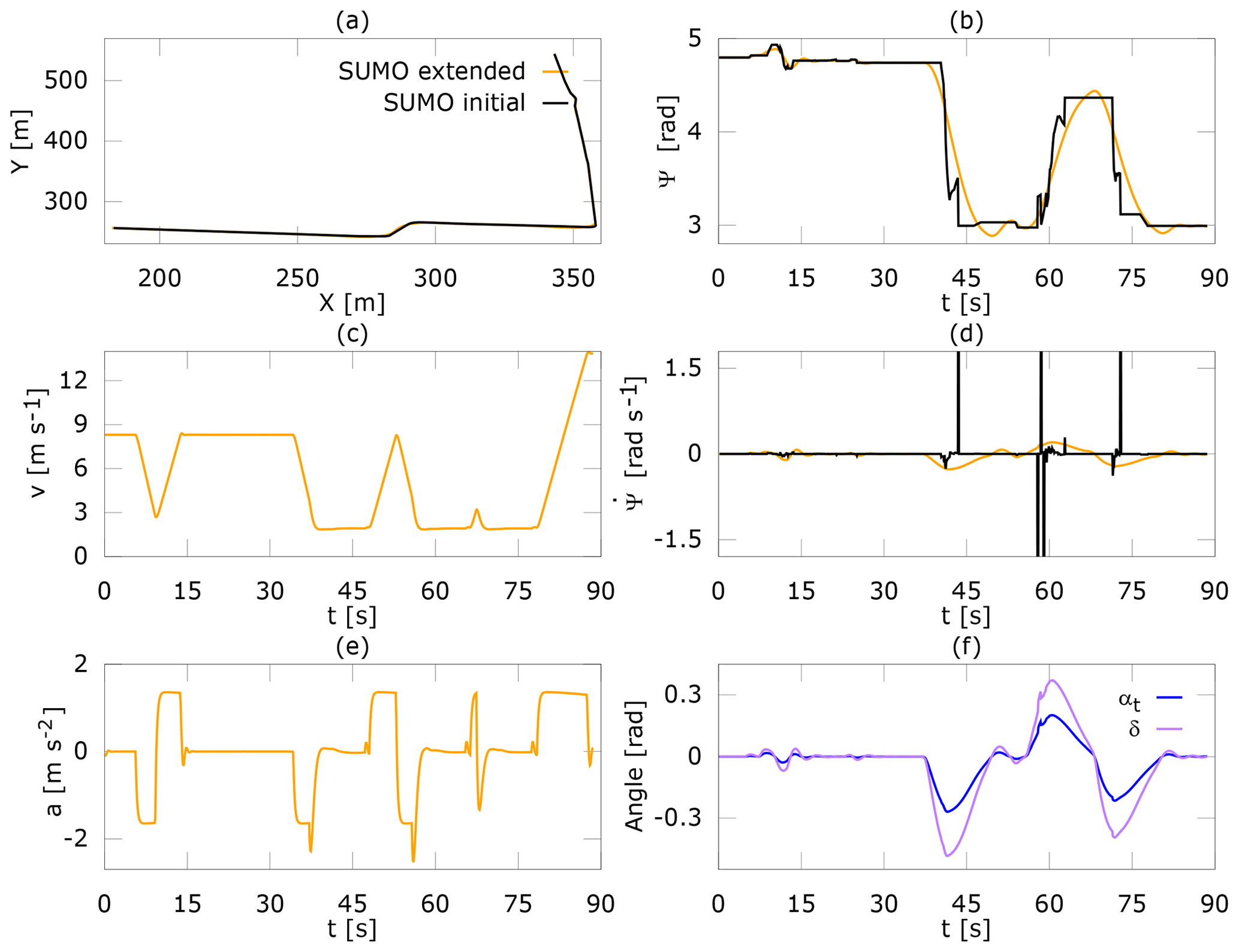
This section evaluates the proposed extensions of SUMO, i.e. the longitudinal and lateral vehicle models as well as the path tracking. For evaluation a map of the sub-urban area Garching is used. Figure 6a shows the trajectory the vehicle is driving in the initial SUMO version and after the extension. The initial trajectory corresponds to the center of lane, which is used as input for the Pure Pursuit algorithm. The vehicle drives from the top to the left bottom. During cornering, the vehicle slightly cuts the corner, which is a typical challenge for the Pure Pursuit controller. In Fig. 6c the velocity is shown. Before cornering the vehicle is braking, and afterwards accelerating. As visible in Fig. 6e the acceleration is not instantaneous available. Figure 6b compares the yaw angles. Adding the lateral vehicle dynamics as described in Sect. 3.2 results in a continuous yaw angle, i.e. there are no abrupt jumps. The yaw rates are compared in Fig. 6d. The initial yaw rate is changing very rapidly and achieves large values due to the discontinuities in the yaw angle. In contrast, the yaw rate after the extension is within a realistic range and continuous. In Fig. 6f, the steering wheel angle and the slip angle are shown.
This paper describes a number of extensions to the simulation tool Artery and its counterpart SUMO. We add longitudinal and lateral vehicle dynamics as well as a lateral controller to the vehicle simulator SUMO. Moreover, Artery's local perception toolbox is extended by probabilistic sensor models and a service for disseminating CPMs. Afterwards, we evaluate the changes regarding the vehicle dynamics. In our view, the framework is now able to be applied for investigation of cooperative perception, which we plan for future work. Adequate network communication models and scalability have already been available and the extensions provide in our view sufficient realistic vehicle movements and sensors. The future work may e.g. include to test different sensor fusion methods or different message formats.
DENSO AUTOMOTIVE Deutschland GmbH has not granted permission for the public accessibility of the source code.
CA investigated appropriate simulation tools. CA conceived the idea to extend the simulation tool Artery as described and carried out the implementation and evaluation. GW supervised the work.
The authors declare that they have no conflict of interest.
This article is part of the special issue “Kleinheubacher Berichte 2018”. It is a result of the Kleinheubacher Tagung 2018, Miltenberg, Germany, 24–26 September 2018.
This research has been supported by the European Commission, H2020 (ADAS&ME (grant no. 688900)).
This paper was edited by Madhu Chandra and reviewed by Andreas Danklmayer and Madhu Chandra.
Aramrattana, M., Larsson, T., Jansson, J., and Nåbo, A.: A Simulation Framework for Cooperative Intelligent Transport Systems Testing and Evaluation, Transport. Res. F-Traf., 61, 268–280, https://doi.org/10.1016/j.trf.2017.08.004, 2017. a
Barthauer, M. and Hafner, A.: Coupling Traffic and Driving Simulation: Taking Advantage of SUMO and SILAB Together, EPiC Series in Engineering, 2, 56–66, 2018. a
BASELABS: Sensor Fusion Library for Algorithm Implementation, available at: https://www.baselabs.de/create/, last access: 15 January 2019. a
ETSI: Intelligent Transport Systems (ITS); Access Layer Specification for Intelligent Transport Systems Operating in the 5 GHz Frequency Band, EN 302 663 V1.3.0, ETSI, 2019. a
Gomez, A. E., Dos Santos, T. C., Filho, C. M., Gomes, D., Perafan, J. C., and Wolf, D. F.: Simulation Platform for Cooperative Vehicle Systems, in: IEEE Intelligent Transportation Systems Conference, 1347–1352, 8–11 October 2014, Hyatt Regency Qingdao, Qingdao, China, 2014. a
Gonzalez, N. and Kalyakin, I.: RACER : A Non-Commercial Driving Game which Became a Serious Tool in the Research of Driver Fatigue, in: Design and Use of Serious Games, Springer, 2009. a
Gruyer, D., Choi, S., Boussard, C., and Andréa-novel, B.: From Virtual to Reality, How to Prototype, Test and Evaluate New ADAS: Application to Automatic Car Parking, in: IEEE Intelligent Vehicles Symposium, 261–267, 8–11 June 2014, Ypsilanti, Michigan, USA, 2014. a
Günther, H. J., Trauer, O., and Wolf, L.: The Potential of Collective Perception in Vehicular Ad-Hoc Networks, in: International Conference on ITS Telecommunications, 1–5, 2–4 December 2015, Copenhagen, Denmark, 2015. a, b, c, d
Günther, H. J., Riebl, R., Wolf, L., and Facchi, C.: Collective Perception and Decentralized Congestion Control in Vehicular Ad-Hoc Networks, in: IEEE Vehicular Networking Conference, 8–10 December 2016, Columbus, OH, USA, 2016. a
Günther, H. J., Riebl, R., Wolf, L., and Facchi, C.: The Effect of Decentralized Congestion Control on Collective Perception in Dense Traffic Scenarios, Comput. Commun., 122, 76–83, 2018. a
International TASS: PreScan/TASS International, available at: https://tass.plm.automation.siemens.com/prescan (last access: 10 January 2019), 2018. a
Kehrle, F., Frasch, J. V., Kirches, C., and Sager, S.: Optimal Control of Formula 1 Race Cars in a VDrift Based Virtual Environment, IFAC Proceedings Volumes, 44, 11907–11912, 2011. a
Krajzewicz, D., Hertkorn, G., and Wagner, P.: SUMO (Simulation of Urban MObility) – An Open-Source Traffic Simulation, in: Proceedings of the 4th Middle East Symposium on Simulation and Modelling, 183–187, January, Sharjah, United Arab Emirates, 2002. a
Llatser, I., Jornod, G., Festag, A., Mansolino, D., Navarro, I., and Martinoli, A.: Simulation of Cooperative Automated Driving by Bidirectional Coupling of Vehicle and Network Simulators, in: IEEE Intelligent Vehicles Symposium, 1881–1886, 11–14 June2017, Los Angeles, CA, USA, 2017. a
Massow, K. and Radusch, I.: A Rapid Prototyping Environment for Cooperative Advanced Driver Assistance Systems, J. Adv. Transport., 2018, 1–32, https://doi.org/10.1155/2018/2586520, 2018. a
Michel, O.: Webots TM : Professional Mobile Robot Simulation, Advanced Robotic Systems, 1, 39–42, 2004. a
ns-3: ns-3/a discrete-event network simulator for internet systems, available at: https://www.nsnam.org/ (last access: 14 January 2019), 2018. a
OMNeT++: OMNeT++, Discrete Event Simulator, available at: https://omnetpp.org/ (last access: 13 January 2019), 2018. a
Pereira, J. L. F. and Rossetti, R. J. F.: An Integrated Architecture for Autonomous Vehicles Simulation, in: Proceedings of the 27th Annual ACM Symposium on Applied Computing, 286–292, 26–30 March 2012, Trento, Italy, 2012. a
PTV Planung Transport Verkehr AG: PTV Vissim, available at: http://vision-traffic.ptvgroup.com/en-us/products/ptv-vissim/ (last access: 13 January 2019), 2018. a
Rajamani, R.: Vehicle Dynamics and Control, Springer, 2006. a, b
Riebl, R., Günther, H. J., Facchi, C., and Wolf, L.: Artery: Extending Veins for VANET applications, in: 2015 International Conference on Models and Technologies for Intelligent Transportation Systems, 450–456, 3–5 June 2015, Budapest, Hungary, 2015. a
Rondinone, M., Maneros, J., Krajzewicz, D., Bauza, R., Cataldi, P., Hrizi, F., Gozalvez, J., Kumar, V., Röckl, M., Lin, L., Lazaro, O., Leguay, J., Härri, J., Vaz, S., Lopez, Y., Sepulcre, M., Wetterwald, M., Blokpoel, R., and Cartolano, F.: ITETRIS: A Modular Simulation Platform for the Large Scale Evaluation of Cooperative ITS Applications, Simul. Model. Pract. Th., 34, 99–125, 2013. a
Automobile-Catalog: The Cataloge of Cars, Cars Specs Database, available at: https://www.automobile-catalog.com/, last access: 23 August 2019. a
Schiller, M., Dupuis, M., Krajzewicz, D., Kern, A., and Knoll, A.: Multi-Resolution Traffic Simulation for Large Scale High Fidelity Evaluation of VANET Applications, SUMO User Conference 2015 – Intermodal Simulation for Intermodal Transport, 17–36, Springer, Berlin, Germany, 2015. a
Schünemann, B.: V2X Simulation Runtime Infrastructure VSimRTI: An Assessment Tool to Design Smart Traffic Management Systems, Comput. Netw., 55, 3189–3198, 2011. a
Segata, M., Joerer, S., Bloessl, B., Sommer, C., Dressler, F., and Cigno, R. L.: Plexe: A Platooning Extension for Veins, in: IEEE Vehicular Networking Conference, 53–60, 3–5 December 2014, Paderborn, Germany, 2015. a, b
Sommer, C., German, R., and Dressler, F.: Bidirectionally coupled network and road simulation for improved IVC analysis, IEEE T. Mobile Comput., 10, 3–15, 2011. a
Wymann, B., Sumner, A., Dimitrakakis, C., Guionneau, C., and Espi, E.: TORCS: The Open Racing Car Simulator, 2015. a