Articles | Volume 18
https://doi.org/10.5194/ars-18-1-2020
10 Dec 2020
 | 10 Dec 2020

Design of a continuously tunable reflectarray element for 5G metrology in the k-band

Thomas Harz, Thomas Kleine-Ostmann, and Thorsten Schrader
Abstract

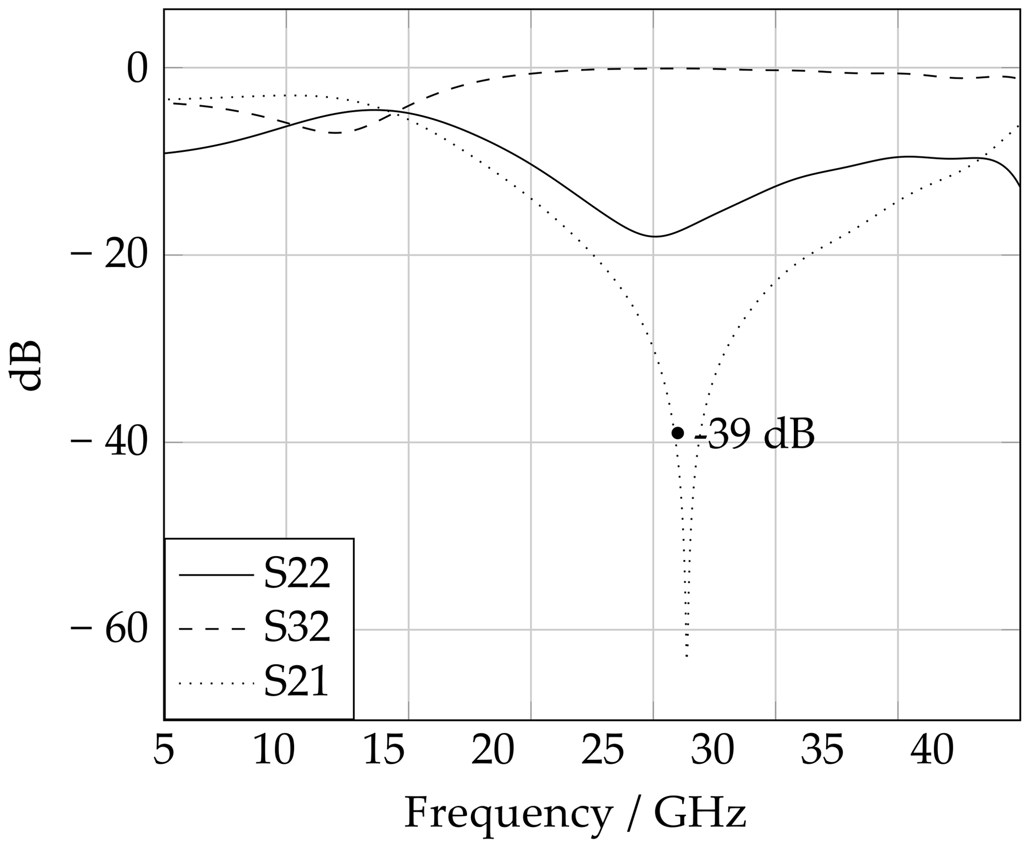
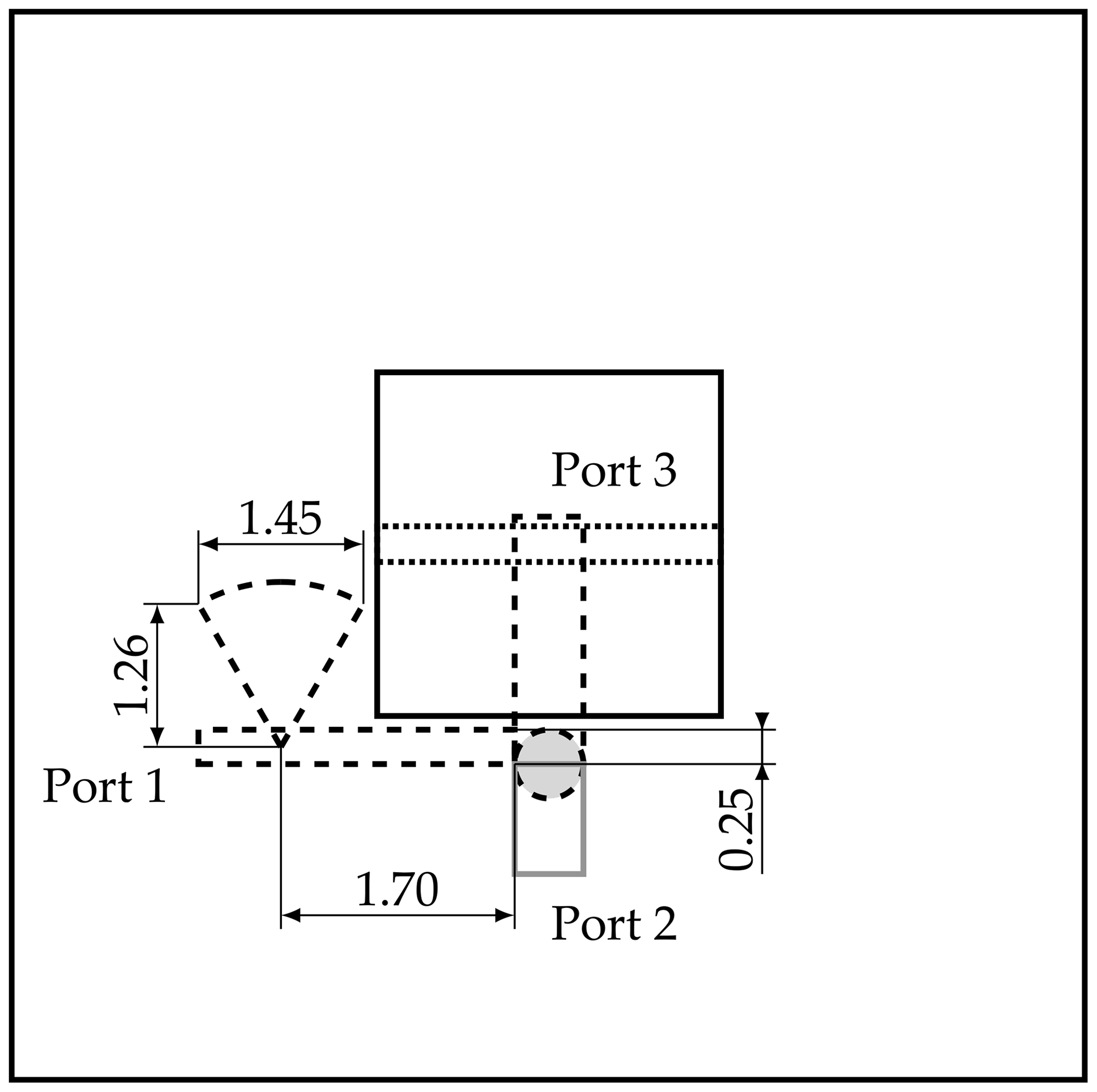
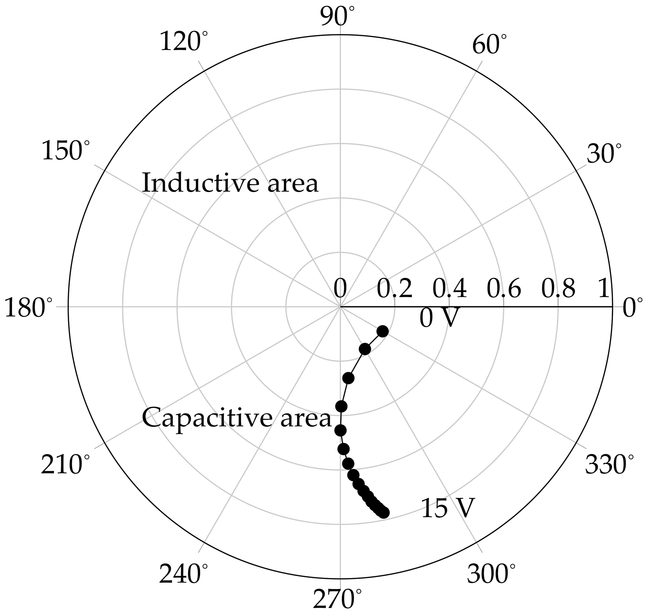
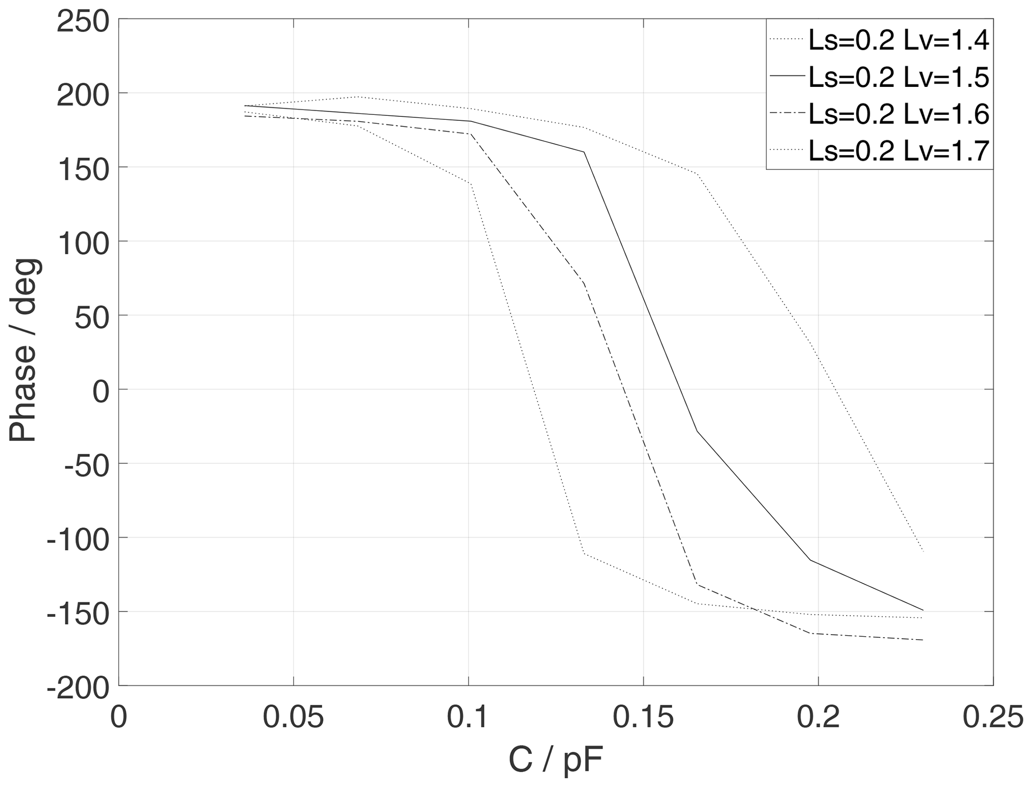
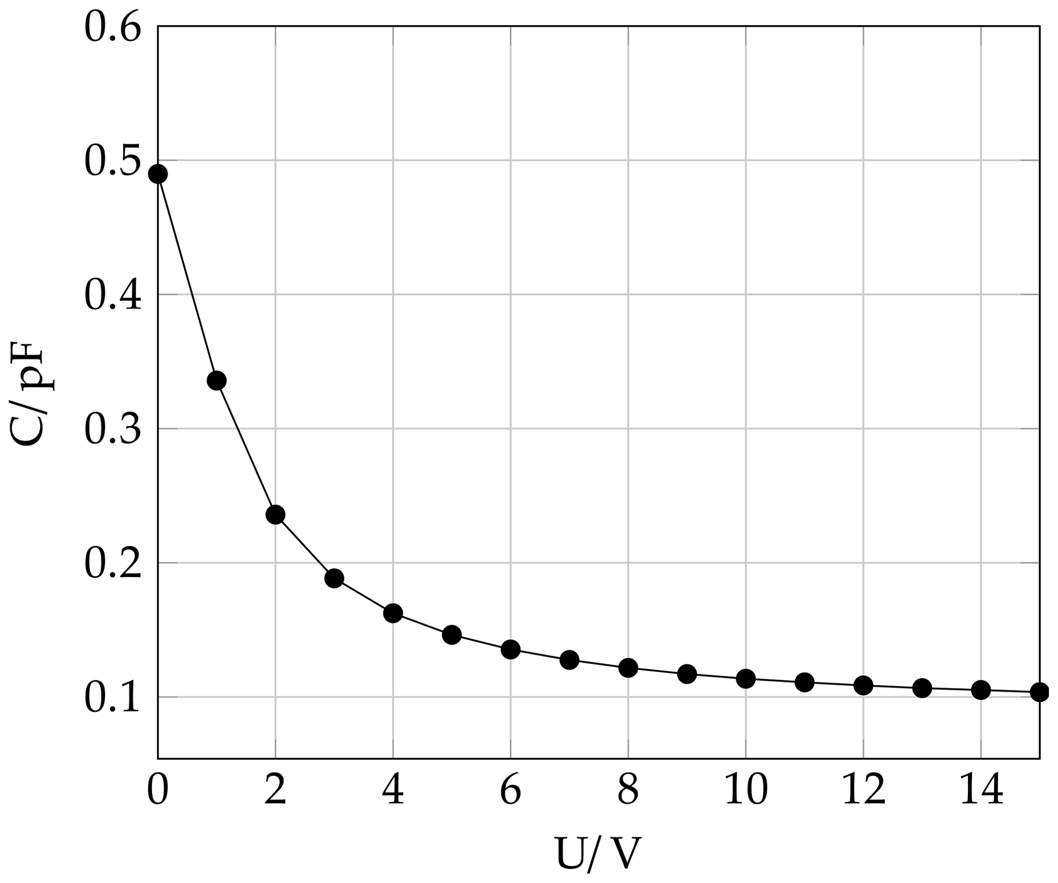
We introduce a new tunable reflectarray element for an operation frequency of 26 GHz in the k-band. It is shown that a 340 continuous tunning range of the reflected wave can be accomplished by using an aperture-coupled patch antenna with only one single varactor diode. The simplified design and the small needed space make it usable for k-band reflectarrays with many elements. The functionality of the reflectarray element is explained and the crucial parts are analyzed. The approach to get a full phase shift is discussed in detail. A bias-T is developed to provide the control voltage to the varactor diode without interfering with the high frequency path. The high frequency path and the DC-path are decoupled by 39 dB using a bias-T. A commercial off-the-shelf varactor diode is selected and its functionality at 26 GHz is verified. Therefore, a test printed circuit board with through, reflect, line standards is developed to de-embed the varactor diode and to evaluate it with a vector network analyzer. The reflectarray is simulated in a unit cell with plane wave excitation and periodic boundary condition using the simulation software package CST Microwave Studio™.

1 Introduction

Using 5G in the mm wave bands will require electronically steerable antenna beams. As a prerequisite for antenna parameter metrology (McKinnis et al., 2018), the Physikalisch-Technische Bundesanstalt (PTB) investigates different antenna designs. Reflectarrays are used in many applications because of their flat design and light weight. They can be produced in a commonly used printed circuit board (PCB) production process. The reflectarray can be designed to obtain fixed beams or steerable-beams in certain directions. In either way, only one transceiver is necessary. Also, no complex beamforming network with losses is needed, which is especially important for k-band application.

Reflectarray antennas are built like parabolic antennas, with a feed and a parabolic reflector. The parabolic reflector is focusing the energy from the feed to the desired direction. The reflectarray replaces the parabolic reflector which consist of many antenna elements. Each element can change the individual phase of the reflected wave. In this way, the direction of the focused beam can be adjusted. The reflectarray combines the functions of parabolic reflector and antenna array (Huang and Encinar, 2008).

Reflectarrays have many advantages compared to conventional antenna arrays. They are easy and cost-efficient to produce. There is no need for complex receiver and transmitter layouts. A beamforming network with high losses especially in the millimetre wave range is not needed.

The drawbacks of a reflectarray are the small bandwidth because of radiator and resonant elements (Venneri et al., 2013) and that the spatial domain and the frequency domain cannot be used independently compared to Active Electronically Scanned Arrays (AESA). The bandwidth of a full reflectarray is measured on its gain-frequency curve. It can be defined as the width where the gain decreases by 1 or 3 dB, only. To the authors' knowledge, the largest bandwidth was pulished by Dahri et al. (2017). This reflectarray with a fixed beam has a fractional bandwith of 32.53 % for a 1 dB drop of the gain.

There are many different approaches for reflectarray design. One is to use an aperture coupled antenna with a microstrip-line. The length of the microstrip-line is changed according to the intended phase of the reflected ray. This technic is used to build a reflectarray with a fixed beam (Zebrowski, 2019). If the beam direction should be variable, a tunable element is needed. For example, with a PIN-diode or MEM-switch the length of micostrip-line can be changed in discrete steps and with the change of the length the phase will change, too (Theissen et al., 2016). It has been shown, that even few discrete steps from one to two bits are degrading the gain at boresight direction. To use more than one or even two bits is not practical for millimeter wave antennas because of the limited space. The necessary bias-T and electronic devices are difficult to fit in the size of the reflectarray element (Ahmad et al., 2017). Because of the few discrete steps and fabrication tolerances, phase errors occur. These phase errors increase the sidelobe level which might not be tolerable (Leberer, 2005). To partly compensate the mentioned issues, a continuously tunable reflectarray element cell is a solution. This can be accomplished with a varactor diode even in the k-band.

This paper discusses an aperture coupled element for the k-band with continuous phase tuning. An aperture coupled design was chosen because it has a flat surface on the reflection site. The circuit elements like the varactor-diode and the bias-T are behind the ground layer. The location of the circuit elements has no influence on how the radiation behaves in a certain direction. The backscattering depends on the patch and the coupled slot, only. No parasitic reflection can occur (Venneri et al., 2012). Furthermore, the mechanical requirements like conductor spacing or trace width fit to the production concept of millimeter wave reflectarrays. The use of only one varactor per element makes the design more controllable in a millimeter wave environment, taking into account the parasitic effects, which occur in this frequency band. Another reason is the limited space in millimeter wave elements which makes it impractical to use a more complex circuit.

The paper is organised as follows. In Sect. 2, the design of the reflectarray element is described, whereas Sect. 3 discusses the design of the bias-T. Section 4 contains the simulation of the antenna element behaviour. In the last Sect. 5 a summary and conclusion is presented.

https://ars.copernicus.org/articles/18/1/2020/ars-18-1-2020-f01

Figure 1Printed circuit board layer stack-up of the reflect array element.

Download

https://ars.copernicus.org/articles/18/1/2020/ars-18-1-2020-f02

Figure 2Layout of the reflect array element (top view).

Download

https://ars.copernicus.org/articles/18/1/2020/ars-18-1-2020-f03

Figure 3Layout of the reflect array element (side view).

Download

2 Reflectarray element

The continuously tuneable reflectarray element consists of six layers (Fig. 1). Four layers are built to reflect the incoming wave with a proper phase shift (Figs. 2, 3). The fifth and sixth layer provide the space to route the bias voltage through the antenna array structure to the other unit cells. They also contain the varactor diode. The proposed unit cell is designed for an operation frequency of 26 GHz. The patch on layer one which receives the incoming wave has a dimension of 2.5 mm×2.5 mm (Wp=2.5mm). The incident wave from the patch is coupled through the rectangular slot to the stripline on layer three. The patch, the slot and the thickness of dielectrics are optimized with CST Microwave Studio™ to achieve the best effectivity of the antenna. The good coupling is obtained with a slot of width Wa=0.26mm and length La=2.5mm. The phase shift over frequency band can be flattened by increasing the height of dielectric between the patch and the slot, which is better for the wideband performance, but the tunable phase shift range will decrease. A compromise between these two issues is found with a height of 0.254 mm of the printed patch. The element bandwidth of the final reflectarray element is at least 100 MHz. This element bandwidth is defined differently, compared to the bandwith of a full reflectarray. It is measured on the phase-frequency curve. On this curve, the frequency range of the bandwidth is determined where the phase of the reflected wave can be contolled in a defined range. The focus is here to have a maximum phase shift. A small slope of the phase over the change of capacity means a better controllable adjustable phase because of the control voltage from the varactor diode. The control voltage has not been finely tuned if the phase curve is flat. A good coupling between the slot and the stripline is simulated with a spacing of 0.254 mm. The stripline with the varactor diode adds the intended phase shift to the wave which is reflected back through the slot to the patch, where the energy is reradiated (Venneri et al., 2013). The ground plane on layer four ensures that less energy is radiated from the backside of the element. The whole element is built on a Rogers RT5870™ substrate because of the small loss. The relative permittivity is specified with 2.33 at 10 GHz. As a good starting value, this permittivity is used in the simulation.

3 Bias-T

To provide the varactor diode with its control voltage without affecting the high frequency path, a bias-T is developed. The bias-T consists of a radial shunt and a λ∕4 line. The λ∕4 line transforms a short of the radial shunt into an open. At the other end of the line, the DC-supply is connected. The high frequency path is decoupled from the DC-path with over 39 dB as shown in Fig. 4. The transmission losses are smaller than 0.1 dB, which is sufficient for the reflectarray. Additional vias are included to suppress any parasitic resonance in layer three but are not shown in Fig. 2. The dimensions are illustrated in Fig. 5.

https://ars.copernicus.org/articles/18/1/2020/ars-18-1-2020-f04

Figure 4Simulated S-parameters of the bias-T. The position of the ports are marked in Fig. 5.

Download

https://ars.copernicus.org/articles/18/1/2020/ars-18-1-2020-f05

Figure 5Dimensions of the bias-T and port description.

Download

4 Simulation in unit cell

The adjustable phase range of the reflectarray also depends on how wide the stripline with the varactor diode can change the phase of the reflected wave. To optimize the phase range, the length of the stripline must be adjusted to the capacity range of the varactor diode (Venneri et al., 2013).

https://ars.copernicus.org/articles/18/1/2020/ars-18-1-2020-f06

Figure 6Polar diagram of the reflection factor of the varactor diode at different voltage levels.

Download

https://ars.copernicus.org/articles/18/1/2020/ars-18-1-2020-f07

Figure 7Simulated phase for different lengths of Lv.

Download

https://ars.copernicus.org/articles/18/1/2020/ars-18-1-2020-f08

Figure 8Capacity voltage curve of the varactor diode.

Download

https://ars.copernicus.org/articles/18/1/2020/ars-18-1-2020-f09

Figure 9Simulated phase for different lengths of Ls.

Download

This is done in a unit cell with plane wave excitation and periodic boundary condition. Therefore, the simulation is performed with CST Microwave Studio™ using the frequency domain solver with the unit cell boundary condition. The unit cell boundary condition simulates the element in a periodic structure and takes the influence of neighbouring elements into account. As mentioned in Venneri et al. (2013) the length Ls of the stripline gives the appropriate inductance to the resonant circuit. The length of Lv together with the varactor diode gives the capacitive load. In other words, with Ls the resonance frequency is shifted to the desired frequency band and with Lv the phase range is fitted to the available capacitive range of the varactor diode. For the reflectarray element, it is intended to use flipchip varactor diodes because of the mounting form, which promises to have less parasitic serial inductance as for example SMD. A large parasitic serial inductance would compensate the capacitive effect of the varactor diode at 26 GHz and a phase change could not be be realized. The selected flipchip diode from Macom MAVR-011020-141™ has a capacitive range from 0.025 to 0.19 pF by a bias voltage range from 0 to 15 V. No equivalent circuit with parasitic values is provided from the manufacturer for the used diode. Therefore, the performance of the diode must be verified: first to make sure that no parasitic effects would degrade the performance of the reflectarray element and second to verify the function of the diode at 26 GHz. For that, the diode is measured on the printed circuit board with a vector network analyzer. To measure in a linear range of the diode, the output power of the vector network analyzer is set to 0 dBm. The printed circuit board includes two connectors and feed lines, which must be de-embedded to get the characteristics of the diode. This is done with a through reflect line (TRL) calibration, where the reference plane is set to the diode's pads. On the board the diode is serially connected between the connectors. The reflection factor of the diode is retrieved, as it is shown in Fig. 6. It is noticeable that also for maximum capacitance of the diode, which occurs at a bias voltage of 0 V, the reflection factor is not inductive. Any reduction of the adjustable phase range from the reflected wave of the element can be neglected because of the parasitic serial inductance from the varactor diode. Accordingly, the reflectarray element is adjusted. With Lv the reflectarray element is fit to the capacitive range (Fig. 7). With Ls the phase range can also be fine-tuned. From the measurement it can be concluded, that the capacitance range from the diode is shifted to higher values in comparison to the information from the data sheet (Fig. 8). To be on the safe side, a phase-capacity curve is selected, which overlap the capacitive range from the datasheet and the measurement. Therefore, the phase-capacity curve with Lv=1.5 is chosen. The width Ws of the stripline is 0.5 mm and the length Lw is 0.8 mm. With Ls=0.2mm an adjustable phase range of 340 is simulated (Fig. 9). The unit cell size is a compromise between phase range and steering angle from the reflect array antenna. If the unit cell size is reduced, the phase range declines and the steering angle of the beam improves. To keep the phase range of 340, a size of x=y=8mm is chosen which is 0.7×λ.

5 Conclusion

The concept of a tuneable reflectarray element has been presented, which is based on the paper of Venneri et al. (2012). It allows a continuous phase tuning of the reflected wave . A comercially available varactor diode is verified for the use at 26 GHz and it is shown that it can provide together with the stripline a phase shift of 340. The reflectarray element is designed to be used at 26 GHz. The structure of the 6-layer reflectarray element has been shown, which is built out of one material, only. Therefore, it can be completely produced in a common printed circuit board production process. The design of the main components of the antenna element has been discussed. Further work will include the simulation of the radiation properties both of single elements and the whole antenna and comparison to measurements.

Data availability

The data are available from the authors upon request.

Author contributions

TS and TKO devised the main conceptual ideas. TH planned and carried out the simulations and measurements. All authors provided critical feedback and helped to write the manuscript.

Competing interests

The authors declare that they have no conflict of interest.

Special issue statement

This article is part of the special issue “Kleinheubacher Berichte 2019”. It is a result of the Kleinheubacher Tagung 2019, Miltenberg, Germany, 23–25 September 2019.

Financial support

This open-access publication was funded by the Physikalisch-Technische Bundesanstalt.

Review statement

This paper was edited by Michael Vogt and reviewed by two anonymous referees.

References

Ahmad, G., Brown, T., Underwood , C., and Loh, T.: How coarse is too coarse in electrically large reflectarray smart antennas?, 2017 International Workshop on Electromagnetics: Applications and Student Innovation Competition, London, 30 May–1 June 2017, pp. 135–137, 2017. 

Dahri, M. H., Jamaluddin, M. H., Abbasi, M. I., and Kamarudin, M. R.: A Review of Wideband Reflectarray Antennas for 5G Communication Systems, IEEE Access, 5, 17803–17815, 2017. 

Huang, J. and Encinar, J. A.: Reflectarray Antennas, Wiley-IEEE Press, New York, 2008. 

Leberer, R.: Untersuchung von quasi-planaren Antennen mit sektorförmiger und omnidirektionaler Strahlungscharakteristik im Millimeterwellenbereich, Cuvillier Verlag, Göttingen, 2005. 

McKinnis, J. M., Gresham, I., and Becker, R.: Figures of Merit for Active Antenna Enabled 5G Communication Networks, 11th Global Symposium on Millimeter Waves (GSMM), CO, USA, USA, 22–24 May 2018. 

Theissen, H., Dahl, C., Rolfes, I., and Musch, T: An electronically reconfigurable reflectarray element based on binary phase shifters for K-band applications, German Microwave Conference (GeMiC), Bochum, 14–16 March 2016, pp. 321–324, 2016. 

Venneri, F., Costanzo, S., Di Massa, G., Borgia, A., Corsonello, P., and Salzano, M.: Design of a reconfigurable reflectarray based on a varactor tuned element, 6th European Conference on Antennas and Propagation (EUCAP), Prague, 26–30 March 2012, pp. 2628–2631, 2012. 

Venneri, F., Costanzo, S., and Massa, G.: Design and Validation of a Reconfigurable Single Varactor-Tuned Reflectarray, IEEE T. Antenn. Propag., 61, 635–645, 2013. 

Zebrowski, M.: Modifications Improve Reflectarray Antennas: available at: https://www.mwrf.com/datasheet/modifications-improve-reflectarray-antennas-pdf-download, last access: 25 April 2019.