 | 21 Mar 2023
Towards Differential Static Magnetic Localization of Commercial Capsule Endoscopes: An Evaluation Using Different Ring and Cylindrical Magnets
Lu Chen
Angelika Thalmayer
Georg Fischer
Jens Kirchner
Capsule endoscopy is a promising diagnostic tool for the entire gastrointestinal tract. Since a patient swallows the capsules, their size must be sufficiently small. The principal built-in components are cameras, silver-oxide batteries, light emitting diodes, and an antenna for transmitting the video. For diagnosis and treatment, the precise localization of the capsules for specific video frames is required. Recently, static magnetic localization of these capsules with an integrated permanent magnet showed promising results. However, in the state-of-the-art, relatively large magnets compared to the small capsules were used. Therefore, in this extended paper, the localization performance of a recently proposed optimized differential static magnetic localization method for different sized disc and ring magnets was evaluated. The ring magnets were designed for integration with the two batteries of commercial capsules. The magnets were evaluated in static and dynamic scenarios to evaluate the performance of the method in a patient's daily life. It was revealed that the mean position and orientation errors did not exceed 5 mm and 4∘, respectively, for all applied magnets except for the 1.5 and 3 mm long disc magnets. Moreover, the results indicated that the ferromagnetic batteries of capsule endoscopes increase the localization performance when they are centered within a diametrical ring magnet. Overall, it was revealed that the localization performance of the optimized differential method is significantly better than the state-of-the-art even when the magnet volume is significantly reduced compared to previous work. Therefore, it was concluded that 5 mm long disc magnet or a ring magnet are excellent candidates for integration into a commercial capsule for magnetic localization and yield the advantage of being passive magnetic sources.
- Article
(3932 KB) - Full-text XML
- BibTeX
- EndNote


Traditionally examinations of the gastrointestinal tract (GIT) are conducted with long flexible endoscopes inserted via the mouth or rectum of a patient. Since the small intestine has a bendy structure, it is challenging to be monitored with traditional endoscopy (Flemming and Cameron, 2018).
About 20 years ago, wireless capsule endoscopy (WCE) was proposed to enable comfortable examination of the entire GIT (including the small intestine) (Iddan et al., 2000). In this procedure, a pill-sized capsule with an integrated camera, silver-oxide batteries, and an antenna for transmitting the video is swallowed by the patient to examine the GIT. Approximately 8 to 12 h required for the capsule to pass through the GIT. Subsequently, doctors retrieve the video for diagnosis and treatment. Commercially available capsule endoscopy systems lack in reliable and accurate localization of those capsules. However, it would be highly relevant for doctors to know the precise position and orientation of the capsule within the GIT for each video frame.
The primary goal of WCE is to make the diagnostic procedure more tolerable for patients and enable their daily activities outside the hospital during the diagnosis procedure that lasts several hours. To make capsule endoscopy more tolerable, the size of the capsule must be sufficiently small. Although WCE has been a research topic for a long time, localization of the capsules in daily life situations of a patient remains an unsolved problem.
Various localization approaches have been proposed to address these problems. These methods can be generally divided into video-based, electromagnetic field-based and magnetic field-based methods (Mateen et al., 2017).
The relative permeability of human tissue is approx. 1, according to Glaser (2000). Therefore, the influence of human tissues on magnetic fields is negligible, which makes them excellent candidates for precise localization of capsule endoscopes. In static magnetic localization, a permanent magnet is integrated into a capsule, and the generated magnetic flux density is measured using a sensor array located outside the body. This results in a localization problem with six unknowns (position and orientation of the capsule). The permanent magnet is approximated as a magnetic dipole, which can be described analytically. A non-linear equation system solved for the position and orientation of the magnet can be derived by subtracting the analytical magnetic flux density from the measured one of each sensor.
However, the geomagnetic flux density Bgeo is of the same order of magnitude as the magnetic flux density at the sensor array (Zeising et al., 2020). Therefore, the localization performance significantly suffers when no compensation method is applied. Over the past few years, several geomagnetic compensation methods have been proposed. Shao et al. (2019) proposed a 3D-sensor array comprising 16 sensors and two additional sensors. The geomagnetic flux density was compensated by subtracting the measured values at the additional sensors from the values of the sensor array. However, the localization performance significantly fluctuated for different magnet positions. Recently, Song et al. (2021) proposed a compensation method using a planar sensor array comprising 16 sensors. The homogeneous Bgeo was canceled out by subtracting the values of two neighboring sensors. The distance between the magnet and the array was fixed at approx. 100 mm. However, Su et al. (2017) found that planar sensor arrays are critically affected when the distance between the magnet and the array varies. Therefore, the assumption of a short distance between the magnet and the array is critical for real applications. A novel differential static magnetic localization system was proposed in 2020 by the authors (Zeising et al., 2020, 2021a). Herein, in total 12 equally oriented sensors were arranged in three rings. The sensors were grouped into six pairs and by subtracting the values of these pairs, Bgeo was eliminated. This method was experimentally evaluated by Zeising et al. (2021d). Subsequently, this method was further optimized by grouping the sensors into 26 pairs (Zeising et al., 2021e). The mean position and orientation errors did not exceed 4 mm and 2∘, respectively, even when the system was moved in a domestic environment with nearby ferromagnetic objects. However, Song et al. (2021) and Shao et al. (2019) both used cylindrical magnets of size 15 mm × 10 mm (length × diameter). In addition, in the previous studies of the authors Zeising et al. (2021d, e) a cylindrical magnet of size 10 mm × 10 mm was used. Unfortunately, commercially available capsules have approximate sizes of 33 mm × 12 mm, which makes it impossible to integrate large magnets.
In this extended paper, the limited space problem of commercial capsules was addressed. Therefore, a ring magnet was designed for integration with the two silver-oxide batteries of commercial capsules. Moreover, disc magnets with different lengths were considered in the measurements. The resulting localization performance in static and dynamic scenarios for applying an optimized differential method was evaluated for each magnet.
Static magnetic localization is a feasible approach for the localization of WCE since the interaction of static magnetic fields with human tissue is negligible. A permanent magnet with volume V and magnetization M0 in A m−1 is integrated into a capsule, located at (Fig. 1). At observer point , the magnet generates a magnetic flux density Bmag(Pobs) in T. If the Euclidean distance , with , between the magnet with a magnetic moment m=M0V in Am2 and the observer is much larger than the size of the magnet, the magnetic dipole model can be applied (according to Jackson, 1962)
Here, is the orientation vector of the magnetic moment direction. The magnetic permeability in vacuum is H m−1 and the relative permeability μr of the surrounding medium, which is approx. 1 for human tissue (Glaser, 2000).
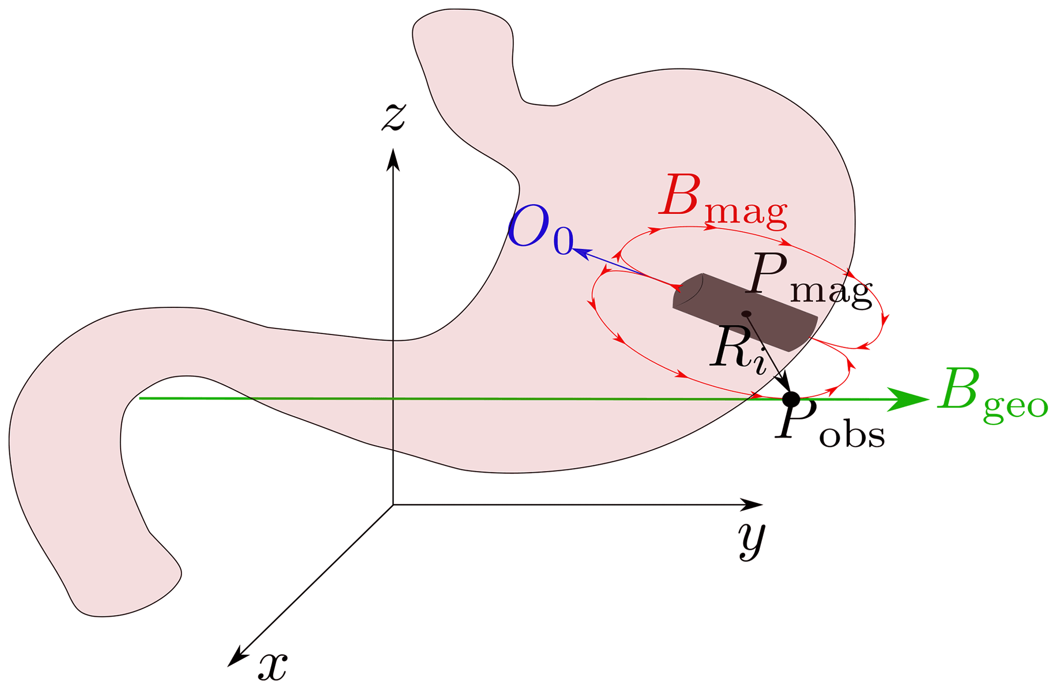
Figure 1Localization scenario of a permanent magnet; the reference coordinate system is depicted. The geomagnetic field Bgeo is interfering.
According to Eq. (1) and with the magnetic flux density at the ith observer point can be expressed as:
The standard static magnetic localization method suggests to subtract the analytical Bi and the measured at the ith known observer position, resulting in three nonlinear equations per known observer point. The resulting nonlinear equation system can be solved for the unknown position and magnetic moment direction of the capsule using the well-established Levenberg-Marquardt (LM) algorithm (Levenberg, 1944; Marquardt, 1963) by minimizing the resulting error function ϵ
By considering the number of unknowns, the magnetic flux density at N observer points (minimal 2) must be evaluated.
The generated magnetic flux density Bmag is static, and therefore, faces an interfering Bgeo. As the magnetic flux density, generated by a permanent magnet decays approx. with (Eq. 1), Bmag at the body surface is of the same order of magnitude as Bgeo (Shao et al., 2019). Hence, the localization performance is significantly affected when no geomagnetic compensation method is applied. The homogeneous geomagnetic field can be calibrated, in a static scenario; however, this is not applicable when the localization system is rotated.
3.1 Localization setup
Figure 2 depicts the experimental setup for validating the differential localization method. The setup consists of polyvinyl chloride (PVC) plates that were fixed together with nylon screws. Three LSM303D sensors were mounted with a distance of 100 mm (in z direction) on each of the four side plates, resulting in 12 sensors. The serial data line of the 12 sensors were connected to a CD74HC4067 multiplexer, which was connected to an Arduino UNO, whereas the serial clock line was directly connected to the Arduino Uno.
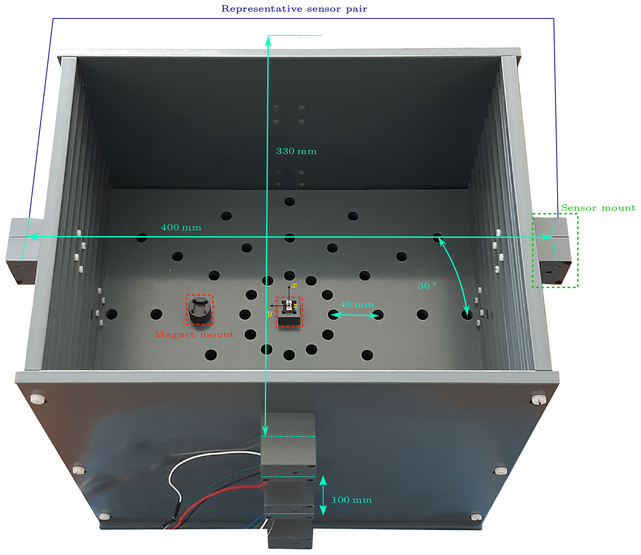
Figure 2Localization setup with sensor and magnet mounts. The magnet is x-orientated and placed at the center of the setup, which is the origin of the reference coordinate system (Zeising et al., 2021d).
The sensors were centered on the sensor mounts. The distance from the sensors on the left side plate to the right side plate was 400 and 330 mm for the top and bottom sides, respectively. For discretely varying the x and y positions of the magnet, holes were arranged in circles with radii ranging from 40 to 160 mm in steps of 40 mm. The holes within were placed with an offset of 30∘. The plate with the holes could additionally be adjusted in the z-direction in steps of 20 mm.
As magnetic field source six different magnets were used, whose sizes and magnetization are summarized in Table 1. Two standard SR48 silver-oxide batteries, which are integrated in commercially available capsules were put in the center of the two ring magnets (Fig. 3).
Table 1Overview of the six different permanent magnets. Two ring magnets of identical size but different magnetization (axial and diametrical) were used.
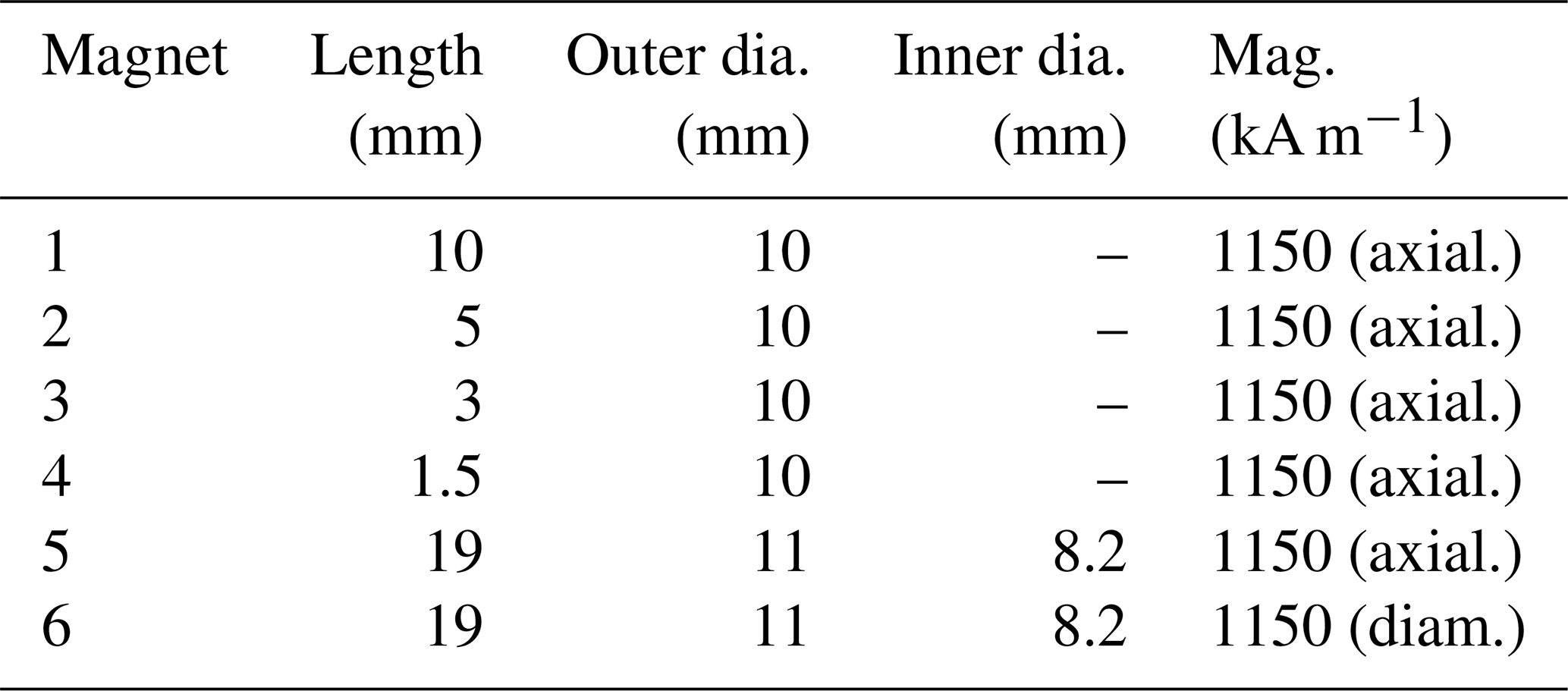
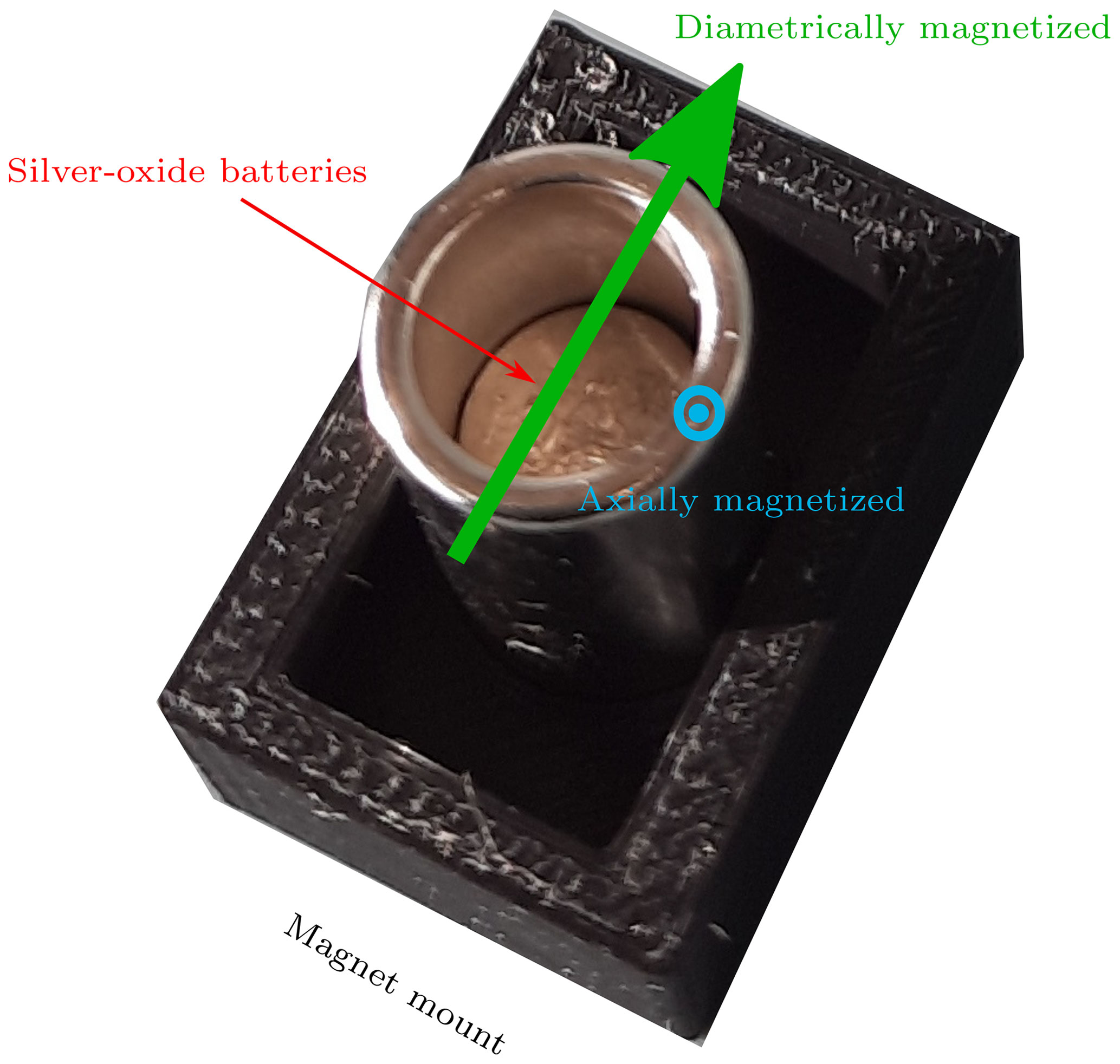
Figure 3Ring magnet with two integrated SR48 silver-oxide batteries. Two different ring magnets were used, an axial and a diametrical ring magnet. The directions of the respective magnetization are depicted.
3.2 Optimized differential localization method
The static magnetic localization method considered in this work is based on the differential localization method proposed and validated in simulations in 2020 (Zeising et al., 2020). It is based on the assumption that Bgeo is homogeneous within the measurement setup. This method was experimentally validated (Zeising et al., 2021d) and optimized (Zeising et al., 2021e); the 12 sensors are grouped into 26 sensor pairs (Fig. 4) instead of 12 pairs of the previous differential method (Zeising et al., 2021d). Each pair consists of two identical sensors (representative pair see Fig. 2). By subtracting the measured flux density of those two sensors, Bgeo cancels out. Subsequently, the standard magnetic localization algorithm (Eq. 5) is applied on the resulting differences.
In contrast to Shao et al. (2019) and Song et al. (2021), the restricting normalization of the magnetic moment direction vector was not considered as an additional equation in the nonlinear equation system. Consequently, the exact knowledge of (see Eq. 1) within the nonlinear equation system was not required because a deviation from the actual l was compensated with the vector length of O0 (). Therefore, a calibration for the unknown magnetization M0 or volume V of the permanent magnet as in Shao et al. (2019); Song et al. (2021) was not necessary, which implies lower measurement uncertainties.
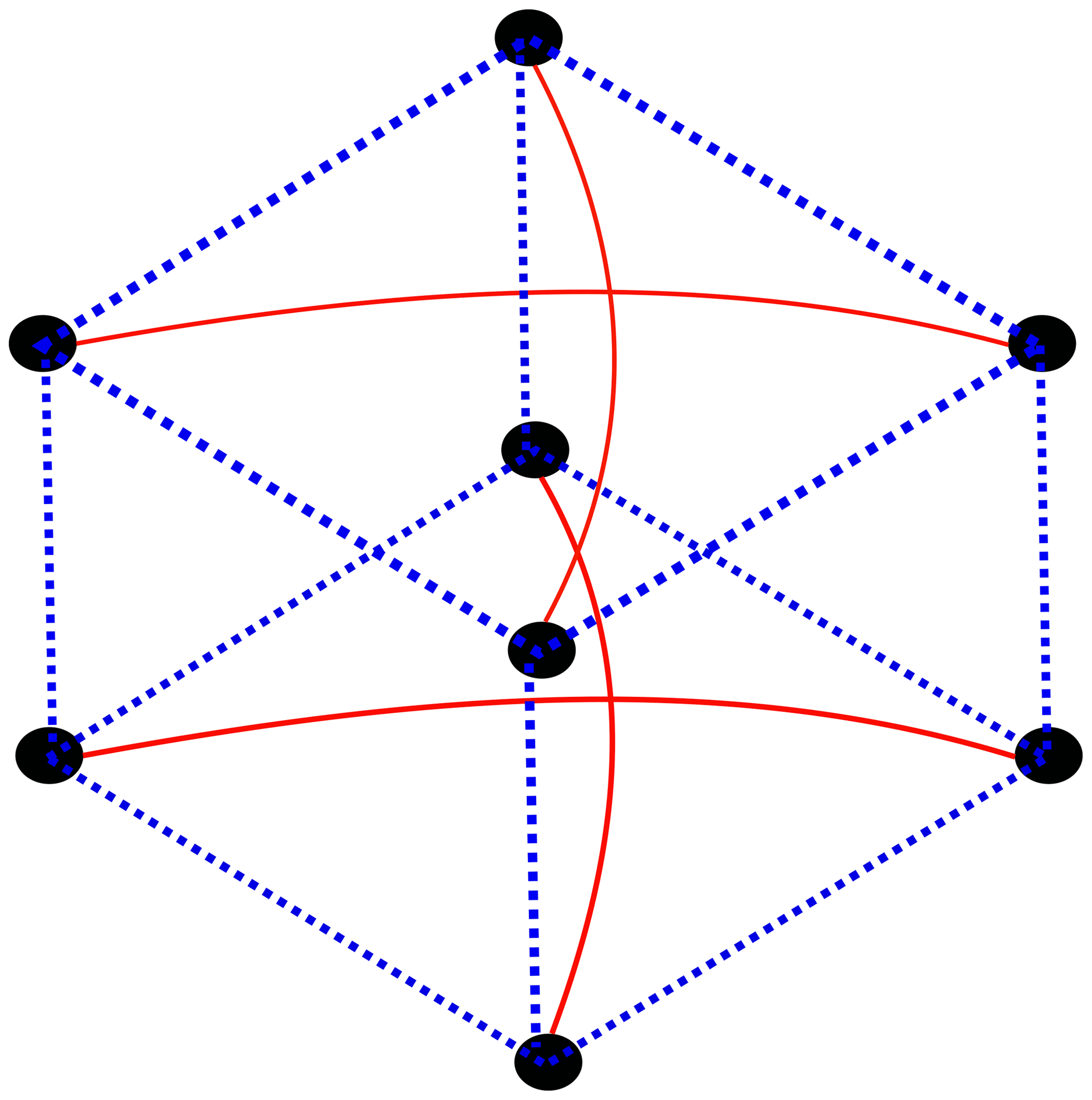
Figure 4Two representative sensor rings are shown, whereas the third sensor ring is not shown. The sensor pairs of the former differential method is depicted in red. The optimized differential method includes the previously defined pairs and is extended by the sensor pairs shown in the blue dotted lines.
3.3 Evaluation procedure
In this study, the performance of the optimized differential localization method was investigated for different sized and shaped magnets (see Table 1) and compared to the previous differential method (Zeising et al., 2021d). Moreover, the two ring magnets were used with and without integrated batteries. The evaluation procedure was two-staged. At first, the setup was evaluated in a static scenario and subsequently, a dynamic scenario was applied. The performance of the localization system was evaluated by deriving the root-mean-square (RMS) position Perr and orientation Oerr errors. The sampling frequency of the magnetic sensors was set to 50 Hz and the mean value for every five samples was derived to calculate the position and orientation of the magnet. Therefore, the magnet was tracked approx. every 0.1 s, which is sufficient considering the relatively slow movement of a capsule inside the GIT.
In the first step of the evaluation, the setup was fixed while 130 magnet positions were applied within a region of the size (160 mm × 160 mm × 200 mm), similar to the size of a typical GIT. In this evaluation step, the magnets were z-oriented. Finally, the mean position and orientation errors were determined for each magnet. The orientation error for the diametrically magnetized ring magnet was not determined since it was not possible to precisely orient the magnet according to its magnetization direction within the setup.
The second scenario was dynamic to represent the daily life activities of a patient. The position of the magnets remained constant at (0, 0, 0) mm, while the magnets were z-oriented. The entire setup was continuously rotated around the z-axis from approx. −90 to 90∘ within 5 s. The corresponding Perr and Oerr were determined for the sampled data.
The results for the discrete variation of the magnet position for applying the optimized and previous differential methods in a static scenario are shown in Figs. 5 and 6 for the six different magnets. In addition, the results for the case that the two batteries are centered within the ring magnets are depicted.

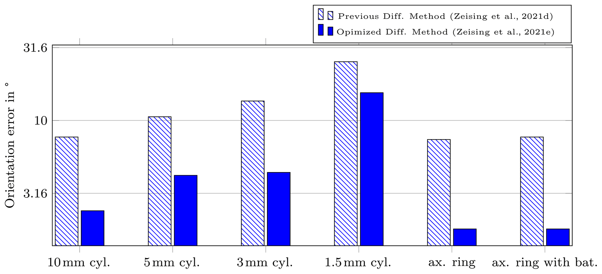
The results for the previous differential method are highlighted with the crossed red bars. The lowest position error was achieved for the diametrical ring magnet with batteries with approx. 6.4 mm and the lowest orientation error for the axially magnetized ring magnet without batteries with approx. 7.4∘. Whereas the localization errors were maximal for the 1.5 mm cylinder magnet with 45.1 mm and 25.3∘, respectively. For the previous differential method, maximal position and orientation errors above 200 mm, and 120∘ were observed for magnet positions far away from the center.
For the optimized differential method, the lowest position error was observed for the diametrical ring magnet with batteries with approx. 2.7 mm. In contrast, the position error was highest for the cylinder magnet of length 1.5 mm with approx. 28 mm. The lowest orientation error was determined for the axially magnetized ring magnet without batteries with approx. 1.8∘. However, it should be noted that the orientation error for the diametrically magnetized ring magnet was not evaluated in this study. The highest orientation error was also observed for the 1.5 mm long cylinder magnet with approx. 16∘.
The results for the dynamic scenario are shown in Figs. 7 and 8.
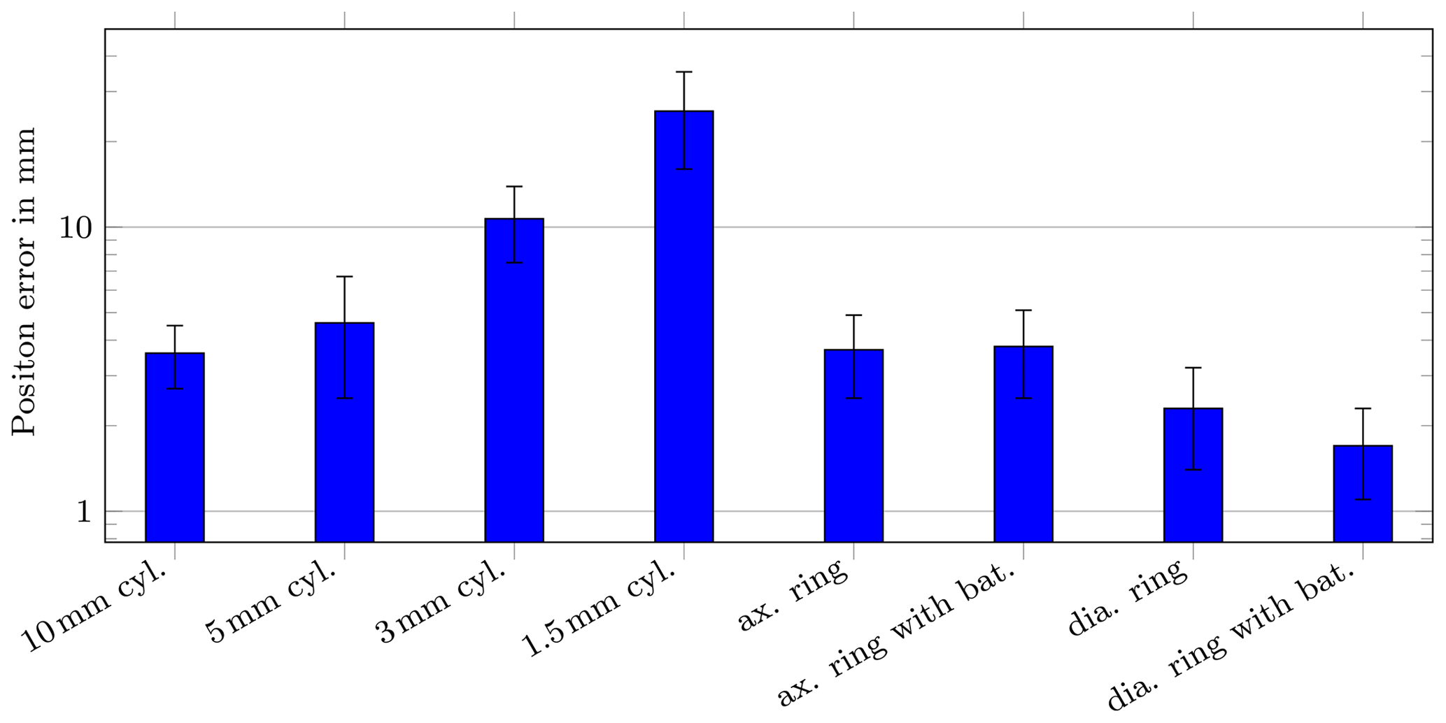
Figure 7Mean position error for the dynamic scenario. The entire system was rotated for 360∘ around the z-axis.
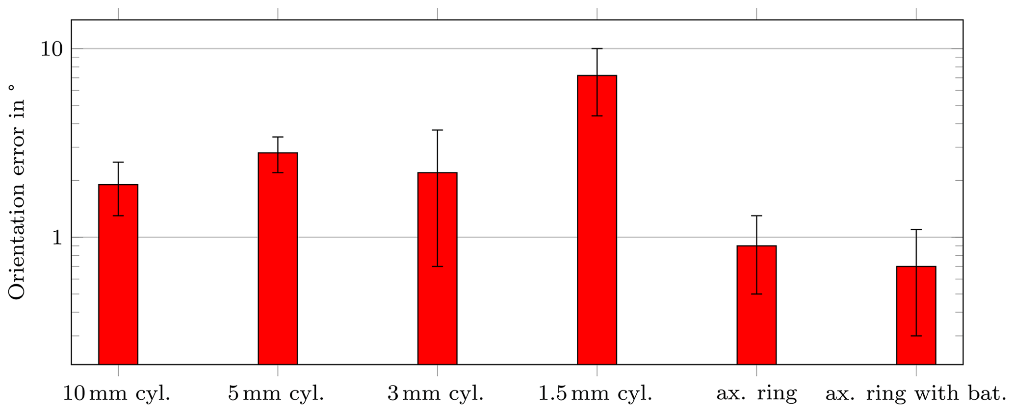
Figure 8Mean orientation error for the dynamic scenario. The entire system was rotated for 360∘ around the z-axis. The diametrical ring magnet was not evaluated for its orientation error.
For the dynamic scenario, the same trend as for the static scenario can be observed. Again, the diametrical ring magnet with batteries achieved the lowest position error with approx. 1.7 mm ± 0.6 mm and the 1.5 mm long cylinder magnet the highest position error with approx. 26 mm ± 9.6 mm, respectively. The orientation errors for the dynamic case did not exceed 3∘ for all applied magnets (except for the 1.5 mm long magnet). Overall, the localization errors for the dynamic scenario were slightly reduced compared to the static scenario. The reason for that is that in the static scenario, the magnet position was varied in a large region, whereas the magnet was located in the center of the setup in the dynamic scenario.
The results demonstrate that the optimized differential localization method significantly outperforms the previous differential method. By using the optimized localization method, the mean position and orientation errors for the different applied magnets were reduced approx. by a factor of two to three. For all applied magnets, excluding the 1.5 and 3 mm long magnets, the mean position and orientation errors in the static and dynamic scenarios did not exceed 5 mm and 5∘, respectively. Since commercial capsules measures up to 33 mm × 12 mm (length × diameter), an accuracy below half of the capsules diameter is regarded as sufficient. Therefore, the magnet lengths of 5 mm at a diameter of 10 mm is considered as the lower boundary for a possible integration into commercial capsules.
It was also observed that the diametrical ring magnet with batteries resulted in the lowest position errors in the static and dynamic scenarios. The reason for this was already found in simulations of Zeising et al. (2021b). The batteries are magnetized in the same direction as the diametrical magnet, and thus, the overall magnetic moment is slightly increased. In contrast, for the axially magnetized ring magnet, the overall magnetic moment is reduced. Additionally, Zeising et al. (2021c) integrated a coil with a similar volume as the proposed ring magnet. The coil was fed by the integrated silver-oxide batteries with current of approx. 15 mA. The coil was localized in simulations with localization errors of approx. 0.5 mm and 0.3∘. However, considering the battery capacity of approx. 75 mAh of commercial capsules and the long diagnosis procedure over several hours, it is not desired to use the batteries also for localization. The results of this extended paper showed that a ring magnet with similar volume results in sufficient localization errors and is a passive magnetic source. Therefore, the integration of a permanent magnet is more feasible.
Table 2 compares the proposed differential localization method with state-of-the-art geomagnetic compensation methods.
Shao et al. (2019)Song et al. (2021)Table 2Comparison of the proposed optimized differential method with state-of-the-art geomagnetic compensation methods for WCE.
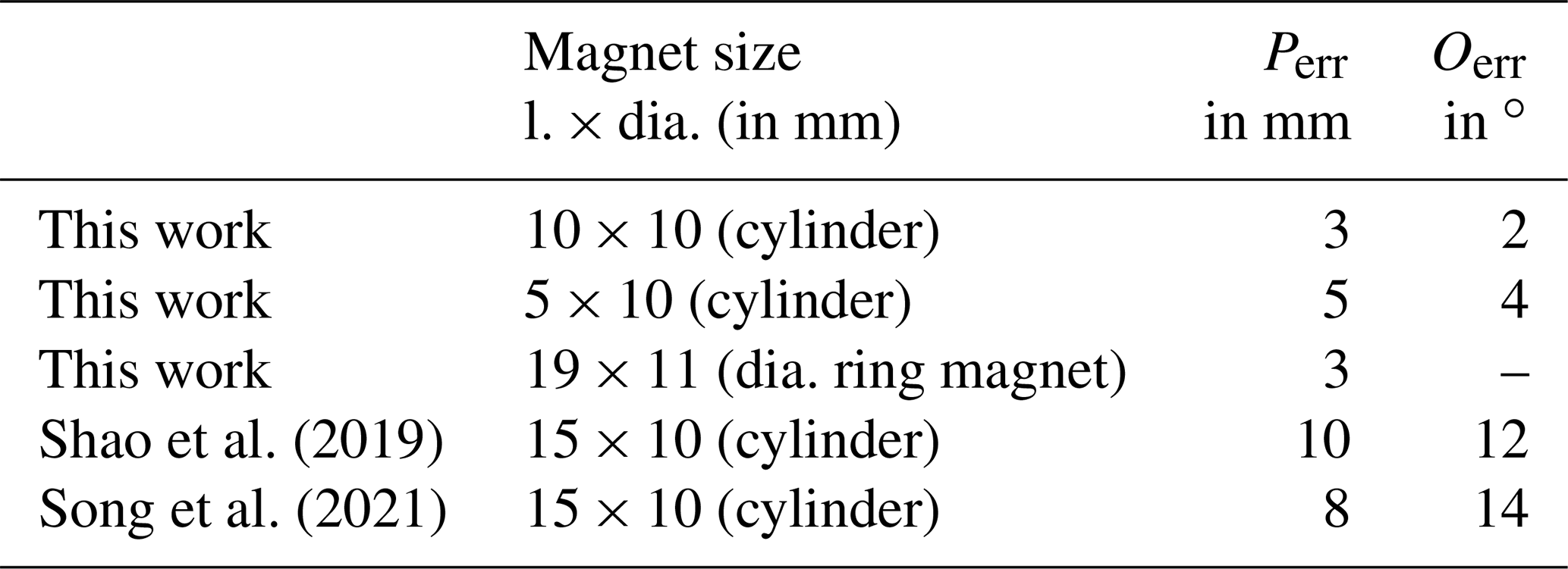
It can be observed that the mean position and orientation errors were significantly lower than state-of-the-art methods for all applied magnets. This is outstanding by considering that the magnet volume of the 5 mm long magnet is 66 % lower than the magnets used by Shao et al. (2019) and Song et al. (2021). Moreover, the results for the dynamic scenario were in good agreement with those of the static scenario, which demonstrates that the system is applicable in the daily life.
The limitation of the study was that only the silver-oxide batteries of commercial capsules were considered for integration within the ring magnet. However, for real application, all built-in components of the capsule should be integrated with the ring magnet. In addition, the magnets were not rotated concerning all three axes, which should be investigated in future work.
In this extended paper, the optimized differential static magnetic localization method for geomagnetic compensation was compared with the previously proposed differential method for magnets of different size and shape. Therefore, the limited space within commercially available capsules for integrating a magnet was addressed. At first, the magnets were evaluated in a static scenario as a reference for the dynamic case. Subsequently, a dynamic scenario was applied, where the setup was rotated while the magnet was fixed in the setup. It was revealed that the mean position and orientation errors by using the optimized localization method were reduced by factors of two to three compared to the previous method for all magnets. Additionally, it was shown that the localization errors for the static and dynamic scenarios were in good agreement, which is crucial for a wearable localization system. Additionally, the mean position and orientation errors did not exceed 5 mm and 4∘, respectively, for all applied magnets (excluding the 1.5 and 3 mm long magnets) and all scenarios. Therefore, the state-of-the-art in static magnetic localization of endoscopy capsules was significantly outperformed even when the magnet volume was reduced by 66 % compared to related studies. It was also confirmed that the localization performance by using a diametrically magnetized ring magnet is enhanced with the ferromagnetic batteries inside a capsule. The limitation of this study was that only the two batteries of commercial capsules were considered for integration with the ring magnet. For real application, all built-in components should be integrated into the ring magnet. Overall, the integration of a small disc or ring magnet into commercial capsules with limited space is feasible and the limited battery capacity is not used for localization. Future research may focus on developing a prototype capsule with an integrated permanent magnet.
The MATLAB-code and data are available from the corresponding author upon request.
SZ initiated the research project. SZ developed the method. SZ and LC carried out the measurements. SZ interpreted the results. SZ and AT carried out the visualization. GF and JK were supervisors. All authors were involved in writing and reviewing the manuscript.
The contact author has declared that none of the authors has any competing interests.
Publisher’s note: Copernicus Publications remains neutral with regard to jurisdictional claims in published maps and institutional affiliations.
This article is part of the special issue “Kleinheubacher Berichte 2021”.
This paper was edited by Lars Ole Fichte and reviewed by Georgiana Rosu and one anonymous referee.
Flemming, J. and Cameron, S.: Small bowel capsule endoscopy, 97, e0148, https://doi.org/10.1097/md.0000000000010148, 2018. a
Glaser, R.: Biophysics: An Introduction, 1st edn., Springer, Berlin/Heidelberg, Germany, ISBN 3540670882, 2000. a, b
Iddan, G., Meron, G., Glukhovsky, A., and Swain, P.: Wireless capsule endoscopy, Nature, 405, 417–418, https://doi.org/10.1038/35013140, 2000. a
Jackson, J. D.: Classical electrodynamics, 1st edn., Wiley, New York, United States, ISBN 0471431311, 1962. a
Levenberg, K.: A method for the solution of certain non-linear problems in least squares, Q. Appl. Math., 2, 164–168, https://doi.org/10.1090/qam/10666, 1944. a
Marquardt, D. W.: An Algorithm for Least-Squares Estimation of Nonlinear Parameters, J. Soc. Ind. Appl. Math., 11, 431–441, https://doi.org/10.1137/0111030, 1963. a
Mateen, H., Basar, R., Ahmed, A. U., and Ahmad, M. Y.: Localization of Wireless Capsule Endoscope: A Systematic Review, IEEE Sens. J., 17, 1197–1206, https://doi.org/10.1109/JSEN.2016.2645945, 2017. a
Shao, G., Tang, Y., Tang, L., Dai, Q., and Guo, Y.-X.: A Novel Passive Magnetic Localization Wearable System for Wireless Capsule Endoscopy, IEEE Sens. J., 19, 3462–3472, https://doi.org/10.1109/JSEN.2019.2894386, 2019. a, b, c, d, e, f, g
Song, S., Wang, S., Yuan, S., Wang, J., Liu, W., and Meng, M. Q.-H.: Magnetic Tracking of Wireless Capsule Endoscope in Mobile Setup Based on Differential Signals, IEEE T. Instrum. Meas., 70, 1–8, https://doi.org/10.1109/tim.2021.3069488, 2021. a, b, c, d, e, f
Su, S., Yang, W., Dai, H., Xia, X., Lin, M., Sun, B., and Hu, C.: Investigation of the Relationship Between Tracking Accuracy and Tracking Distance of a Novel Magnetic Tracking System, IEEE Sens. J., 17, 4928–4937, https://doi.org/10.1109/jsen.2017.2713886, 2017. a
Zeising, S., Ararat, K., Thalmayer, A., Anzai, D., Fischer, G., and Kirchner, J.: Performance Optimization of a Differential Method for Localization of Capsule Endoscopes, Eng. Proc., 2, 31, https://doi.org/10.3390/ecsa-7-08271, 2020. a, b, c
Zeising, S., Anzai, D., Thalmayer, A., Fischer, G., and Kirchner, J.: Innovative Differential Magnetic Localization Method for Capsule Endoscopy to Prevent Interference Caused by the Geomagnetic Field, Adv. Radio Sci., 19, 207–213, https://doi.org/10.5194/ars-19-207-2021, 2021a. a
Zeising, S., Ararat, K., Thalmayer, A., Fischer, G., and Kirchner, J.: Utilizing the Ferromagnetic Battery of Capsule Endoscopes for Static Magnetic Localization, in: 2021 IEEE 19th International Symposium on Antenna Technology and Applied Electromagnetics (ANTEM), Virtual Conference, 8–11 August 2021, https://doi.org/10.1109/antem51107.2021.9519119, 2021b. a
Zeising, S., Seidl, R., Thalmayer, A., Fischer, G., and Kirchner, J.: Quasi-Static Magnetic Localization of Capsule Endoscopes with an Active Integrated Coil, in: 2021 IEEE Sensors Applications Symposium (SAS), Virtual Conference, 23–25 August 2021, https://doi.org/10.1109/sas51076.2021.9530052, 2021c. a
Zeising, S., Thalmayer, A., Fischer, G., and Kirchner, J.: Toward Magnetic Localization of Capsule Endoscopes during Daily Life Activities, in: Kleinheubach Conference 2021, 28–30 September 2021, https://doi.org/10.23919/ieeeconf54431.2021.9598378, 2021d. a, b, c, d, e, f
Zeising, S., Thalmayer, A., Fischer, G., and Kirchner, J.: Differential Geomagnetic Compensation Method for the Static Magnetic Localization of Capsule Endoscopes During Activities of the Daily Life, IEEE T. Instrum. Meas., 71, 1–10, https://doi.org/10.1109/tim.2021.3129206, 2021e. a, b, c