 | 21 Mar 2023
Impact of Additional Antenna Groundplanes on RTK-GNSS Positioning Accuracy of UAVs
Thomas F. Eibert
Precise position information is important for terrestrial and airborne surveying systems, such as unmanned aerial vehicles (UAVs). Those systems often rely on real-time kinematic (RTK) global navigation satellite systems (GNSSs) for position determination, where the GNSS antenna mounting environment impacts the GNSS position accuracy to a great extent. This paper investigates the impact of different supplementary groundplane shapes, sizes, and materials on multi-band patch and helical GNSS antennas at both, the UAV rover and RTK base station with respect to the achievable position accuracy. The groundplanes consist of solid aluminum sheets or copper plated printed circuit boards (PCBs) and are mounted directly underneath the GNSS antennas. Appropriate supplementary groundplanes are found to significantly improve the GNSS position accuracy in the majority of test cases.
- Article
(4946 KB) - Full-text XML
- BibTeX
- EndNote


Nowadays, unmanned aerial vehicles (UAVs) are used for a large variety of applications, also impacting antenna measurements (Umeyama et al., 2020; Cadavid et al., 2018; Garcia-Fernandez et al., 2018). In situ UAV-based antenna measurements are of particular interest for physically large antennas, e.g., reflector antennas for satellite communication (Punzet et al., 2022), where traditional antenna measurement techniques in an anechoic chamber are not applicable. Precise position information in UAV-based measurements is not only a prerequisite to obtain correct and reliable measurement results, but also for safe operation of the UAV. The mechanical system UAV shows six degrees of freedom (6DOF). The UAV orientation (e.g., roll, pitch, and yaw angles) and, thus, the orientation of the probe-antenna(s) is determined via inertial measurement units (IMUs) integrated in the UAV flight controller (FC). Furthermore, global navigation satellite systems (GNSSs) determine the 3-dimensional (3D) spatial coordinates (e.g., x, y, and z in Cartesian coordinates) of the UAV (Punzet and Eibert, 2021).
Standard standalone GNSS receivers achieve a position accuracy in the meter-range (Eissfeller et al., 2007), which is not sufficient for many surveying systems. Real-time kinematic (RTK) GNSS is a technique used to improve the position accuracy by using multiple GNSS receivers. The RTK base station at a fixed location derives its location via received GNSS signals and computes the error in this measurement by comparison to its fixed location. It then sends the error information as correction data to the rover. The rover uses the correction data to improve its own position, also computed from GNSS and, thus, can achieve centimeter-level position accuracy (Kaplan and Hegarty, 2006). Hence, RTK-positioning is of particular interest for measurement applications, such as UAV-based antenna measurements.
Not only the implementation of the GNSS receiver itself, but also the receiving GNSS antenna is a critical system component. Maximum satellite coverage and most reliable position data are obtained with multi-band GNSS antennas, where detailed information on radiation patterns, material properties or simulation models are often not available. An additional groundplane may be beneficial or even required, depending on the antenna design. Hence, the impact of the antenna mounting environment must be evaluated experimentally.
The influence of different groundplane materials, shapes, and sizes on the achievable position accuracy of lightweight multi-band patch and helical GNSS antennas mounted on a UAV was investigated in Punzet and Eibert (2021). This paper continues this research investigating different groundplane configurations of the RTK base station with respect to the achievable position accuracy.
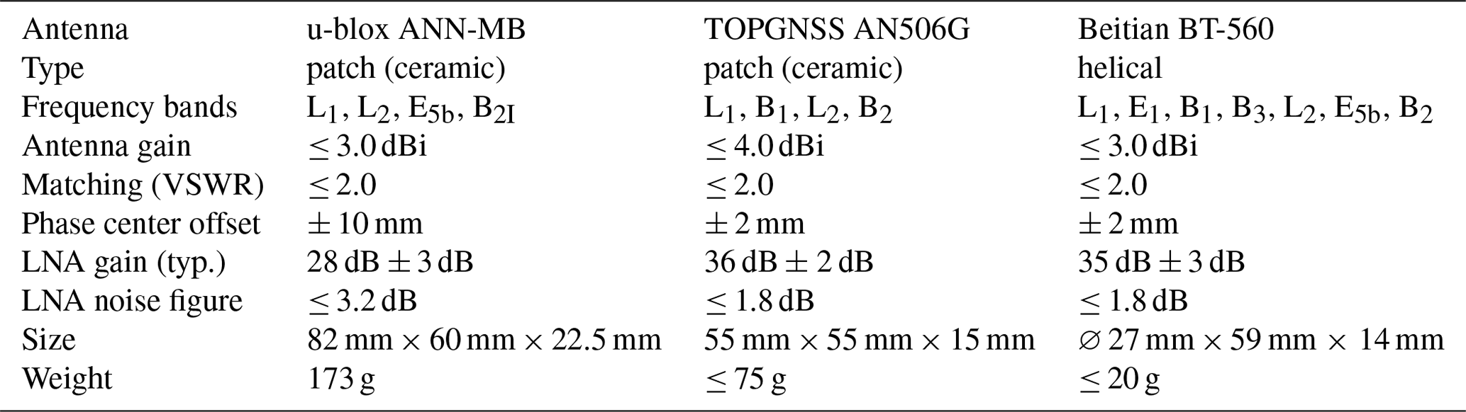
The investigated antennas are shown in Fig. 1. Table 1 lists an excerpt of the antenna data. All antennas include low noise amplifiers (LNAs), support multi-band operation, and are right-hand circular polarized (RHCP). The TOPGNSS and Beitian antenna are lightweight and compact in size, making them highly applicable for UAVs. The u-blox antenna includes a permanent magnet for mounting it onto ferromagnetic structures, making this antenna unsuitable for usage on UAVs, as it interferes with the magnetic compass built into the UAV flight controller.
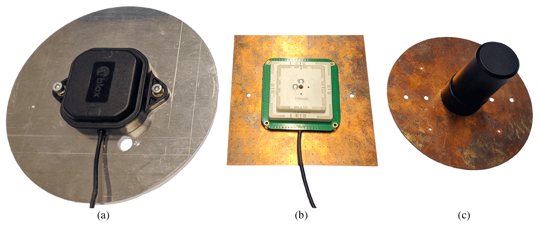
Figure 1Investigated antennas. (a) u-blox ANN-MB patch antenna mounted on the ∅ 15 cm circular aluminum groundplane. (b) TOPGNSS AN506G patch antenna mounted on the 10 cm × 10 cm square PCB groundplane. (c) Beitian BT-560 helical antenna mounted on the ∅ 10 cm circular PCB groundplane.
Table 1Excerpt of the tested GNSS antennas data sheets (u-blox, 2019a; TOPGNSS, 2020; Beitian, 2020). All antennas are right-hand circular polarized (RHCP), support multi-band operation and include low noise amplifiers (LNAs).
The received GNSS signals are decoded and processed by two u-blox ZED-F9P GNSS receivers with the firmware version HPG 1.13, one configured as rover and the other configured as RTK base station. Besides RTK-positioning, the receivers also support standalone operation and the GNSSs global positioning system (GPS), global navigation satellite system (GLONASS), Galileo and BeiDou navigation satellite system (BDS) in the frequency bands L1OF, L, E, B1I, L2OF, L2C, E5b and B2I (u-blox, 2021).
The RTK base station uses the u-blox ANN-MB patch antenna, which was bundled with the u-blox ZED-F9P GNSS receiver. The antenna requires an additional groundplane (u-blox, 2019a), which was confirmed in our tests. No GNSS reception could be established with groundplanes of a diameter smaller than 12 cm. Therefore, the RTK base station antenna remained mounted on a 6 mm thick solid aluminum groundplane, during all test. Here, two different groundplane shapes were investigated; one square 30 cm × 30 cm large and a circular one with a diameter of ∅ 15 cm.
Consecutive measurements were taken where both antennas, rover and RTK base station, remained at a fixed outdoor location in 1.5 m height above ground. Thereby, different supplementary groundplanes were mounted directly underneath the GNSS antenna on the UAV:
-
None, built-in antenna only
-
∅ 10 cm circle, 1.6 mm thick PCB, double- sided copper plated flame retardant 4 (FR4) (weight: 20.89 g)
-
10 cm × 10 cm square, 1.6 mm thick PCB, double-sided copper plated FR4 (weight: 23.91 g)
-
∅ 15 cm circle, 6 mm thick solid aluminum (weight: 231.8 g)
-
30 cm × 30 cm square, 6 mm thick solid aluminum (weight: 1.455 kg)
The GNSS position was recorded for t=600 s, which equals N=3000 samples at a position update rate of 5 Hz, as this approximately corresponds to the maximum continuous flight time with the current UAV setup.
We calculate the deviation around the mean position of all measured n∈N positions
for latitude (p=Lat), longitude (p=Lon) and altitude (p=Alt) and twice the distance root mean square (2DRMS) (Sanz Subirana et al., 2013, p. 150)
Furthermore, We define two figures of merit (FoM) as performance metric for the 3D position accuracy of the UAV, as a UAV shows 6DOF:
-
The standard deviation σ2D=SD(Δ2DRMS) for the horizontal error
-
the standard deviation σAlt=SD(ΔAlt) for the vertical error,
where both approach a value of zero for a non-moving GNSS receiver (like in the investigated scenario) and in the case of perfect position accuracy. By using two distinct FoMs, we can distinguish the influence of the additional groundplanes on the horizontal and vertical error separately.
Table 2 lists the measured results.
Table 2Measured impact of different groundplane configurations on position accuracy for the investigated GNSS antennas with RTK-positioning.
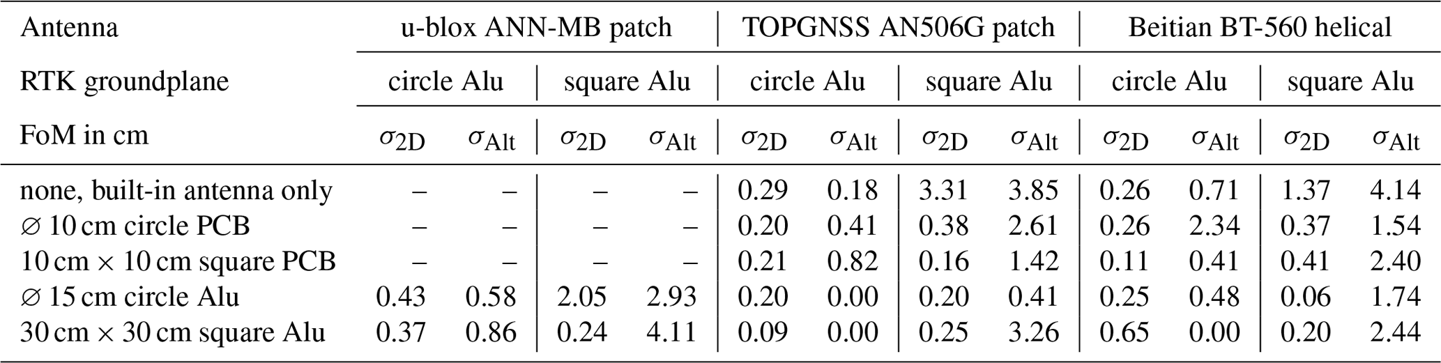
The impact of different groundplanes on the u-blox ANN-MB antenna is of particular interest, since it is used for the RTK base station and the rover corrects its computed location based on the correction data provided by the RTK base station. Concerning all 12 tested cases, measurements showed worse σAlt in 11 cases and worse σ2D in 8 cases, when utilizing the 30 cm × 30 cm square aluminum groundplane instead of the ∅ 15 cm round aluminum groundplane on the u-blox ANN-MB antenna at the RTK base station. No GNSS reception could be established with groundplanes of a diameter smaller than 12 cm, which was to be expected, since the antenna requires an additional groundplane (u-blox, 2019a).
Patch antennas with small groundplanes show back lobes in their radiation pattern (Balanis, 2016). This makes them susceptible to multi-path GNSS signals, e.g., reflected off the ground (Punzet and Eibert, 2021). A larger groundplane mitigates this effect (u-blox, 2019b). In case of the TOPGNSS AN506G patch antenna, utilizing the ∅ 15 cm round aluminum groundplane (Fig. 3a) instead of the 30 cm × 30 cm square aluminum groundplane (Fig. 2a) at the RTK base station showed equal or lower σ2D in 9 out of 10 tested cases. Furthermore, utilizing the ∅ 15 cm round aluminum groundplane at the RTK base station significantly reduced the variation in altitude over time (Fig. 2b) compared to the 30 cm × 30 cm square aluminum groundplane at the RTK base station (Fig. 3b). The smallest overall deviation was achievable with the ∅ 15 cm or 30 cm × 30 cm aluminum additional groundplane underneath the antenna. The TOPGNSS patch antenna seems to benefit from a larger supplementary groundplane. However, in the case that a large additional groundplane is not implementable on the UAV, the best tradeoff with low overall deviation was achievable without a supplementary groundplane.
In case of the Beitian BT-560 helical antenna, utilizing the ∅ 15 cm round aluminum groundplane (Fig. 5a) instead of the 30 cm × 30 cm square aluminum groundplane (Fig. 4a) at the RTK base station showed equal or lower σ2D in 8 out of 10 tested cases. Furthermore, utilizing the ∅ 15 cm round aluminum groundplane at the RTK base station significantly reduced the variation in altitude over time (Fig. 4b) compared to the 30 cm × 30 cm square aluminum groundplane at the RTK base station (Fig. 5b). The lowest overall deviation was achievable with the 10 cm × 10 cm square PCB additional groundplane underneath the antenna.
Replacing the 30 cm × 30 cm square by the ∅ 15 cm aluminum groundplane at the RTK base station improved the altitude FoM σAlt by a factor of up to 21 and the horizontal FoM σ2D by a factor of up to 11. Adding a supplementary groundplane to the rover GNSS antenna improved the altitude FoM σAlt by a factor of up to 9 and the horizontal FoM σ2D by a factor of up to 22. In all investigated cases, we achieved best position accuracy (σ2D=0.09 cm and σAlt=0.00 cm) with the u-blox ANN-MB antenna combined with the 30 cm × 30 cm square aluminum groundplane at the RTK base station and the TOPGNSS AN506G patch antenna combined with the 30 cm × 30 cm square aluminum groundplane at the rover. However, such a large supplementary groundplane at the rover is not practical due to size and weight constrains of the UAV.
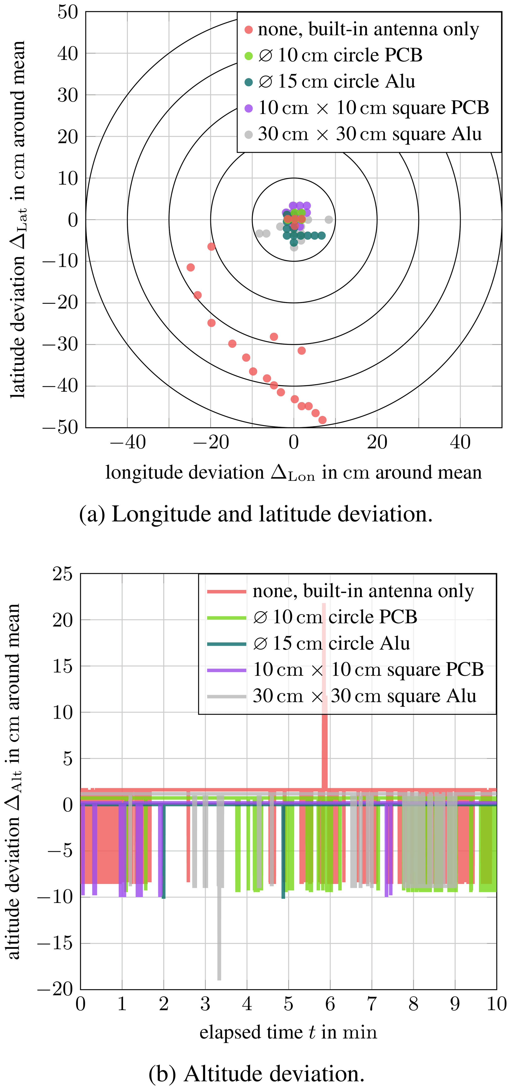
Figure 2TOPGNSS AN506G patch antenna in conjunction with the 30 cm × 30 cm square aluminum groundplane at the RTK base station.
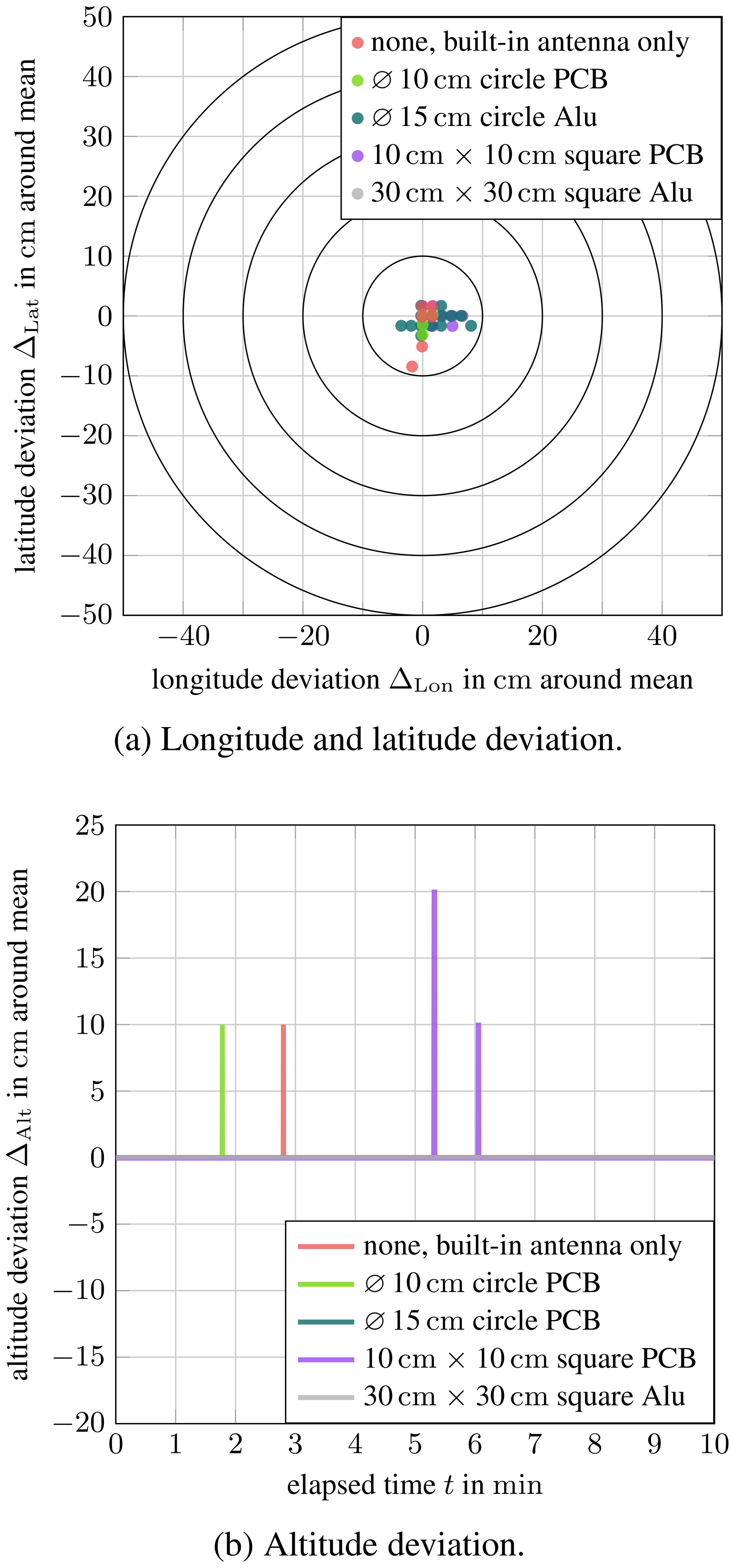
Figure 3TOPGNSS AN506G patch antenna in conjunction with the ∅ 15 cm circular aluminum groundplane at the RTK base station.
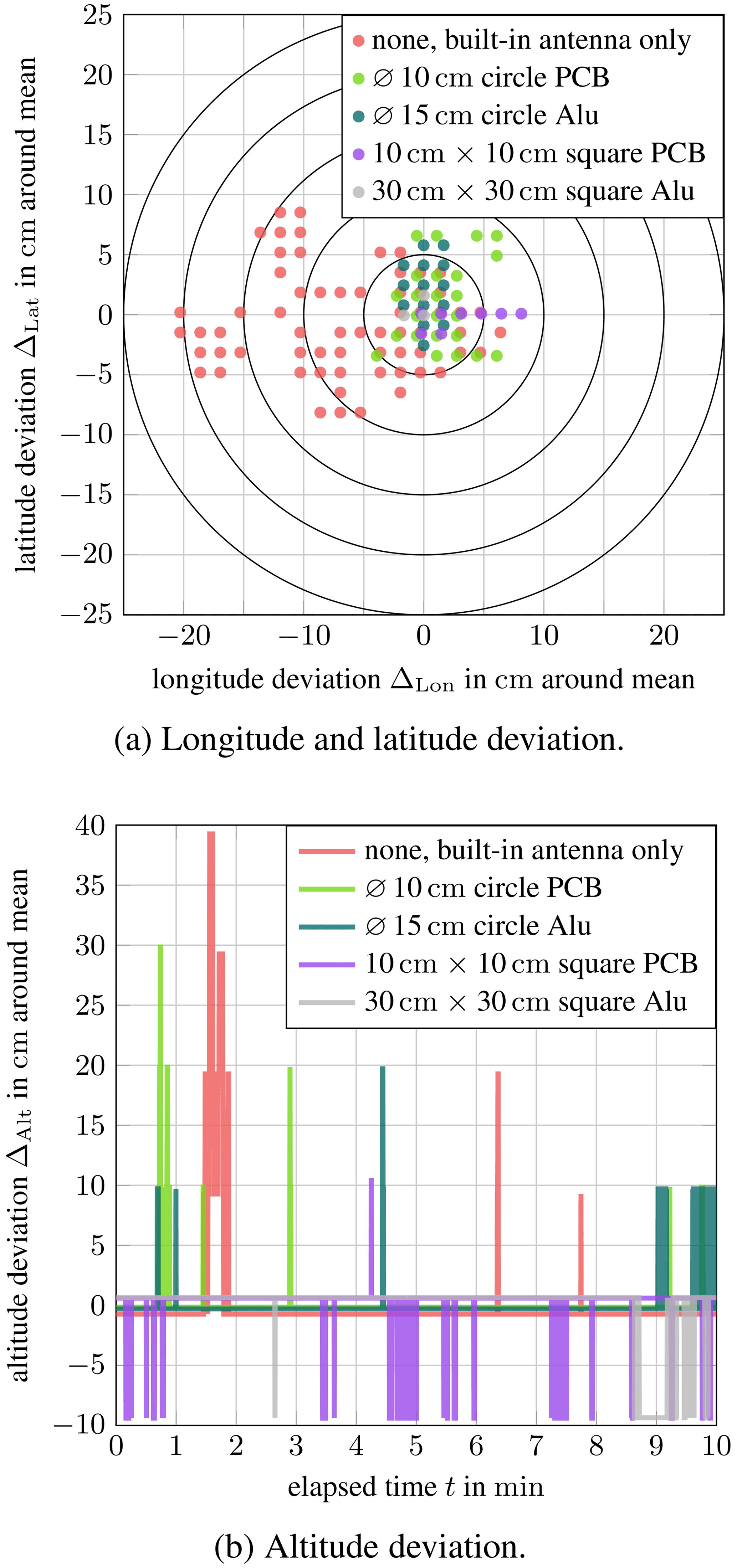
Figure 4Beitian BT-560 helical antenna in conjunction with the 30 cm × 30 cm square aluminum groundplane at the RTK base station.
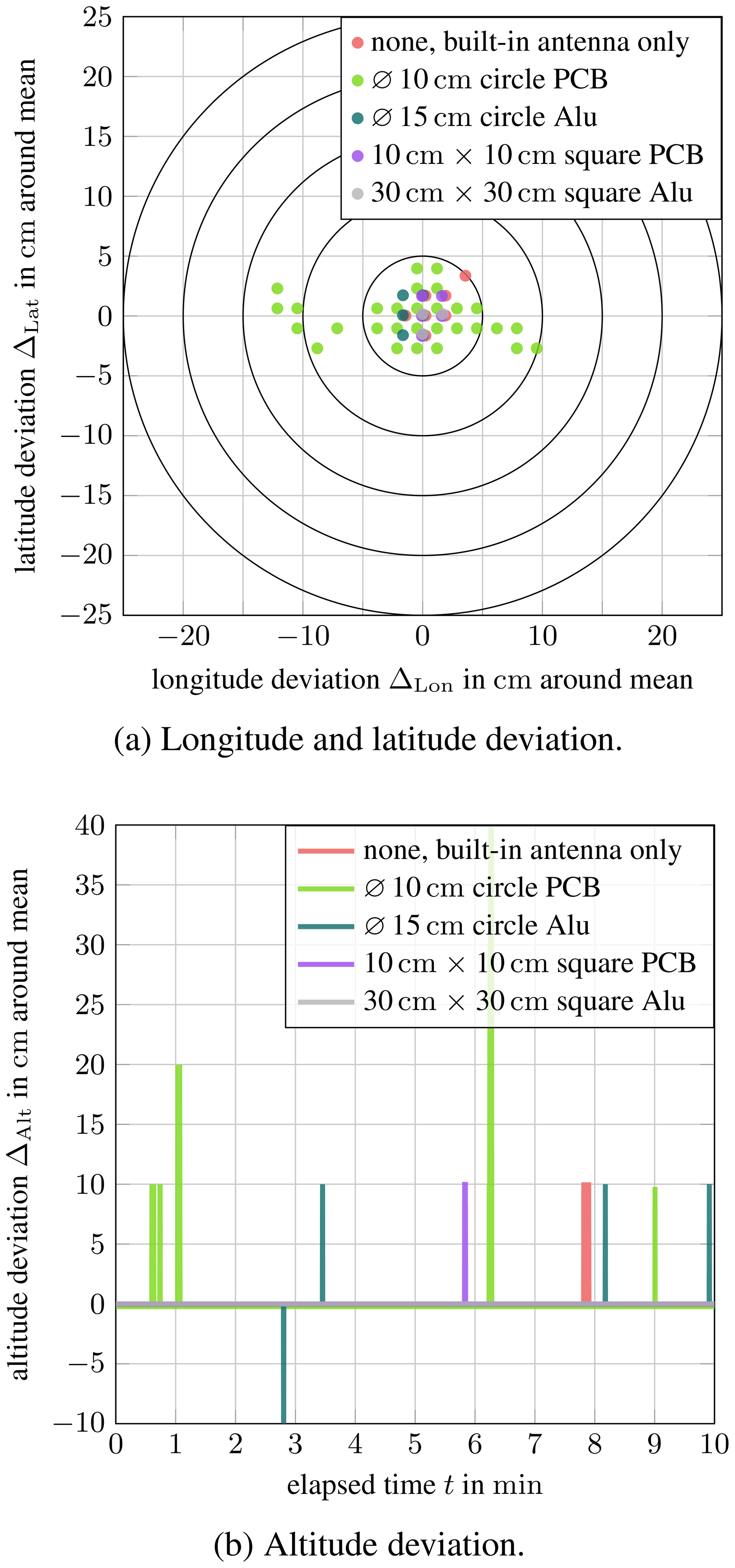
Figure 5Beitian BT-560 helical antenna in conjunction with the ∅ 15 cm circular aluminum groundplane at the RTK base station.
Choosing an appropriate groundplane for the rover and RTK base station GNSS antenna significantly influences the achievable GNSS position accuracy of a flying UAV. Especially the RTK base station antenna shows a substantial impact on the achievable position accuracy, since the rover corrects its position based on the correction data supplied by the RTK base station. An optimal additional groundplane for GNSS antennas must mitigate multi-path signals while maintaining a sufficient antenna axial-ratio preserving the RHCP of GNSS signals. However, the optimum groundplane size and shape depend on the particular GNSS antenna and must, therefore, be evaluated on a per-antenna basis (Punzet and Eibert, 2021).
The underlying research data can be requested from the authors.
SP developed the experiment methodology, conducted the experiments and validated measured data. SP wrote the manuscript in consultation with TFE. TFE supervised the findings of this work. All authors discussed the results and contributed to the final manuscript.
The contact author has declared that neither they nor their co-author has any competing interests.
Publisher’s note: Copernicus Publications remains neutral with regard to jurisdictional claims in published maps and institutional affiliations.
This article is part of the special issue “Kleinheubacher Berichte 2021”.
This research has been supported in parts by the Bundesministerium für Wirtschaft und Energie (grant no. 50RK1923).
This paper was edited by Romanus Dyczij-Edlinger and reviewed by Ralph Helmar Rasshofer and one anonymous referee.
Balanis, C. A.: Antenna theory: Analysis and design, Wiley, Hoboken, New Jersey, 4th Edn., ISBN 978-1-11864-206-1, 2016. a
Beitian: Beitian BT-560 GNSS helical antenna – Data sheet, http://www.sz-beitian.com/FileDownload?path=%27Productsdoc/20210622075343.pdf (last access: 25 June 2021), rev. 5.51, 2020. a
Cadavid, A. N., Aristizabal, J., and Alhucema, M. D. P.: Antenna pattern verification for Digital TV Broadcast systems in Andean countries based on UAV’s, in: IEEE-APS Topical Conference on Antennas and Propagation in Wireless Communications (APWC), IEEE Xplore, 858–861, https://doi.org/10.1109/APWC.2018.8503765, 2018. a
Eissfeller, B., Ameres, G., Kropp, V., and Sanroma, D.: Performance of GPS, GLONASS and Galileo, in: Photogrammetric Week, edited by: Fritsch, D., Vol. 7, 185–199, Wichmann Verlag, Heidelberg, https://phowo.ifp.uni-stuttgart.de/publications/phowo07/220Eissfeller.pdf (last access: 25 June 2021), 2007. a
Garcia-Fernandez, M., Alvarez-Lopez, Y., and Las-Heras, F.: UAV-based antenna measurement and diagnostics for circularly polarized antenna arrays, in: IEEE International Symposium on Antennas and Propagation USNC/URSI National Radio Science Meeting, IEEE, 525–526, https://doi.org/10.1109/APUSNCURSINRSM.2018.8608471, 2018. a
Kaplan, E. D. and Hegarty, C. J.: Understanding GPS: Principles and applications, edited by: Kaplan, E. D. and Hegarty, C. J., Artech House, Boston, Mass. and London, 2nd Edn., 2006. a
Punzet, S. and Eibert, T. F.: Influence of the GNSS Antenna Mounting Environment on Positioning Accuracy of UAVs, in: Kleinheubach Conference, IEEE, 1–4, https://doi.org/10.23919/IEEECONF54431.2021.9598415, 2021. a, b, c, d
Punzet, S., Faul, F. T., Mittereder, T., Oettl, C., Ganser, M., Häusler, M., and Eibert, T. F.: Fully Coherent UAV-Based Near-Field Measurement and Transformation of the S67-15 m Ground Station Antenna at the German Space Operations Center in Weilheim, in: 16th European Conference on Antennas and Propagation (EuCAP) (EuCAP 2022), 30 March 2022, Madrid, Spain, 2022. a
Sanz Subirana, J., Juan Zornoza, J. M., and Hernández-Pajares, M.: GNSS Data Processing: Volume I: Fundamentals and algorithms, edited by: Fletcher, K., Vol. 1, ESA Communications, Noordwijk, ISBN: 978-92-9221-886-7, 2013. a
TOPGNSS: TOPGNSS AN506G GNSS patch antenna – Data sheet, https://de.aliexpress.com/item/1005001350312342.html?spm=a2g0o.store_pc_groupList.8148356.24.5b537e9e9Ry2uv (last access: 6 September 2021), 2020. a
u-blox: ANN-MB series Multi-band, high precision GNSS antennas – Data Sheet, u-blox, https://www.u-blox.com/sites/default/files/ANN-MB_DataSheet_%28UBX-18049862%29.pdf (last access: 30 October 2021), rev. R04, 2019a. a, b, c
u-blox: GNSS antennas – RF design considerations for u-blox GNSS receivers – Application note, u-blox, https://www.u-blox.com/en/docs/UBX-15030289 (last access: 26 September 2021), rev. R03, 2019b. a
u-blox: ZED-F9P-02B – u-blox F9 high precision GNSS module – Data sheet, u-blox, rev. R08, 2021. a
Umeyama, A. Y., Salazar-Cerreno, J. L., and Fulton, C. J.: UAV-Based Far-Field Antenna Pattern Measurement Method for Polarimetric Weather Radars: Simulation and Error Analysis, IEEE Access, 8, 191124–191137, https://doi.org/10.1109/ACCESS.2020.3027790, 2020. a