 | 21 Mar 2023
Susceptibility of Commercial-Off-The-Shelf Sensors to IEMI using Pulse Modulated Signals
Louis Cesbron Lavau
Michael Suhrke
Peter Knott
The use of sensors has grown dramatically in recent years and many devices rely on the information they provide. The lack of proper security mechanisms available to control the use of sensors and the high degree of integration make them more vulnerable to Intentional Electromagnetic Interference (IEMI). The aim of this paper was to investigate the impact of IEMI on separate sensors with privileged access to the hardware and software to pursue a deep analysis of the effects of IEMI attacks using pulse modulated signals. Measurements were carried out in a shielded hall using an open TEM (Transverse Electromagnetic) waveguide in the 100 MHz–7.5 GHz frequency range. A variety of effects were observed and significant differences were found with pulse modulated signals compared to continuous wave signals. These results indicate weak points in the sensors hardware leading to possible hardening measures.
- Article
(3362 KB) - Full-text XML
- BibTeX
- EndNote


Due to increasing digitalization, sensors are used in many areas of life. In particular, decreasing costs as well as miniaturization in the course of technical progress result in more and more new fields of application. Whereas in earlier times sensors were primarily found in industrial plants for process control and monitoring, vehicles, cell phones and, more generally, the cities of the future, the smart cities, are now equipped with a large number of sensors. The growing popularity and utility of these devices in various application areas has allowed the device industry to grow at a rapid pace. According to a report by Fortune Business Insights (2021), the global Internet of Things (IoT) market is projected to grow from USD 381.30 billion in 2021 to USD 1 854.76 billion in 2028 at a Compound Annual Growth Rate (CAGR) of 25.4 % in forecast period.
These embedded systems rely heavily on the integrity of their input and output signals to ensure proper operation. Signals from sensors, whether analogue or digital, are blindly trusted by embedded systems to estimate the environment the system is monitoring and responding to. Most embedded systems secure the sensor readings after they are taken, which, without dedicated counter measures, makes them vulnerable to attacks that target the sensor directly (Fu et al., 2018).
The use of sensors in IoT devices inevitably increases the functionality of the devices. However, sensors can also be used to launch attacks on devices or applications. For example, there have been several recent attempts to exploit the security of IoT devices via their sensors (Son et al., 2015; Nahapetian, 2016; Sikder et al., 2017; Trippel et al., 2017). Attackers can use the sensors to transfer malicious code or a trigger message to activate malware embedded in the device (Hasan et al., 2013; Subramanian et al., 2013), capture sensitive personal information shared between devices (e.g., smartphone, smartwatch, etc., Zhuang et al., 2009; Schlegel et al., 2011; Maiti et al., 2015), or even extract encrypted information by capturing encryption and decryption keys (Del Pozo et al., 2015).
Another type of attack is the use of Intentional Electromagnetic Interference (IEMI; Radasky et al., 2004): to induce noise or inject false data into electronic devices. The impact of IEMI on common electronic systems (Nitsch et al., 2004; Bäckström et al., 2004), IT equipment (Hoad et al., 2004), or commercial buildings (Parfenov et al., 2004) has been shown in numerous papers and various recent studies have begun to examine this impact on sensor systems in particular. Some IEMI attacks are using direct signals injected on the sensor circuits in order to interfere with the analog signals leading to false sensor's outputs (Richelli, 2016; Ware, 2017; Zhang et al., 2020). Other attacks are executed remotely from a few meters with the same objectives using an antenna knowing the most effective frequencies, this has been demonstrated for example on an electrocardiogram (Kune et al., 2013) or a temperature sensor (Tu et al., 2019). Two recent papers (Giechaskiel and Rasmussen, 2020; Yan et al., 2020) summarized the different attacks and threats on analog sensors using direct power and remote signal injection. The previous described attacks are using low power in comparison to High-Power Electromagnetics (HPEM) attacks, also employed either to destroy hardware components or to induce false readings in sensor systems, for example on UAV sensor system (Esteves et al., 2018; Lubkowski et al., 2020). These sensor-based threats can pose a significant risk to IoT systems and applications compared to conventional attacks.
To protect autonomous and embedded systems, an important requirement is to ensure information security, the practice of preventing unauthorized access, disruption, modification, or destruction of information. Information Security (InfoSec) programs are built around three objectives: availability, integrity and confidentiality. The first objective of InfoSec is availability: meaning that authorised individuals are able to access their data whenever they want. Some attacks could lead to system crash, restart or communication errors making the system unavailable for the user and sensors can be used as an entry point. The second objective of InfoSec is integrity: it involves maintaining the accuracy, consistency and trustworthiness of data. The goal is to trick a sensor into providing seemingly legitimate but erroneous measurements, the system will trust the sensor as it seems legitimate and this could lead to disastrous consequences. Last objective is confidentiality and it is about implementing measures that are designed to stop unauthorised individuals accessing sensitive data, whilst ensuring authorised individuals can still access it.
Embedded systems are integrating more and more components and sensors. This complexification is making it harder to understand and explain the effects of attacks such as HPEM, as all components are in close proximity of each other and interlinked, increasing the number of entry points and making difficult to assess the components individually. Moreover, the access of observable data is also a challenge, usually protected and encrypted by manufacturers preventing a real-time analysis.
The aim of this study is to investigate the susceptibility of stand-alone sensors. Different HPEM signals are used: results with Continuous Wave (CW) signals are presented in (Cesbron Lavau et al., 2021) and this paper investigates the use of Pulse Modulated (PM) signals (varying the pulse period and/or width). The choice of these sensors is made on the privileged access to the hardware and software to pursue a deep analysis of the effects of HPEM attacks.
This paper is organized as follows: in Sect. 2, the sensors used are described and the methodology from the test environment to the monitoring system is explained. First results are provided and discussed in Sect. 3. Conclusions are finally provided in Sect. 4.
2.1 Test Setup
Three different commercial-off-the-shelf sensors were tested: a magnetometer, a barometric pressure sensor and a current sensor. These sensors are integrated and used in different embedded systems such as UAVs, smartphones or smartwatches. The magnetometer sensor performs measurements of the magnetic field in three orthogonal directions (X, Y, Z). The barometric pressure sensor is based on a capacitive sensing principle, capable of measuring both pressure and temperature. Finally, the current sensor is a coreless magnetic sensor measuring the magnetic field induced by the current flowing between two probes. The main interest in this sensor stems from its highly linear output signal. The sensors were built on separated boards with the capacitors and pull-up resistors and then connected to the same microprocessor using pin headers. The microprocessor was protected against RF irradiation in an enclosed aluminium box while the different PCBs (Printed Circuit Board) were exposed. The sensors were chosen due to the ease of access to their raw measurement data and communication interfaces. Figure 1 is showing the aluminium box (in grey) with the pin headers (in black) as well as the PCBs (in red). The two communication interfaces used were an Inter-Integrated Circuit (I2C) for the magnetometer and barometer sensors and a Serial Peripheral Interface (SPI) for the current sensor. The communication with the microcontroller and the monitoring system outside the shielded hall is done using fibre optic cables (in orange on Fig. 1).
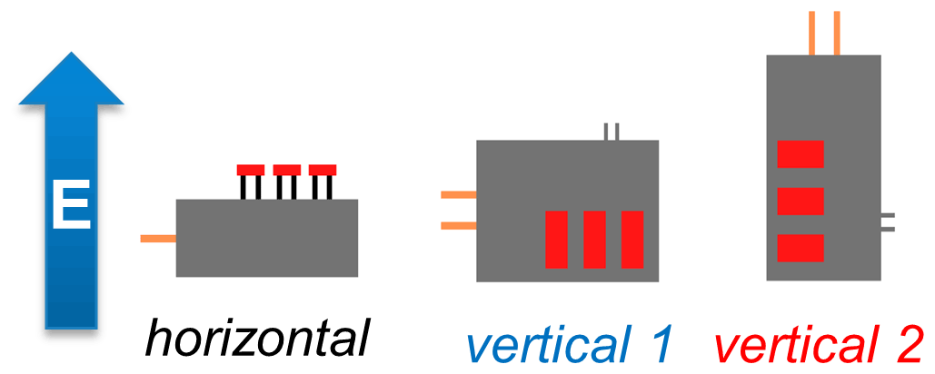
The measurements of the sensor's vulnerability to IEMI were carried out in a shielded hall using an open TEM (Transverse Electromagnetic) waveguide. The TEM waveguide only illuminates with one electromagnetic field polarization, so to investigate others, the DUT (Device Under Test) has to be rotated. Three different DUT orientations have been investigated:
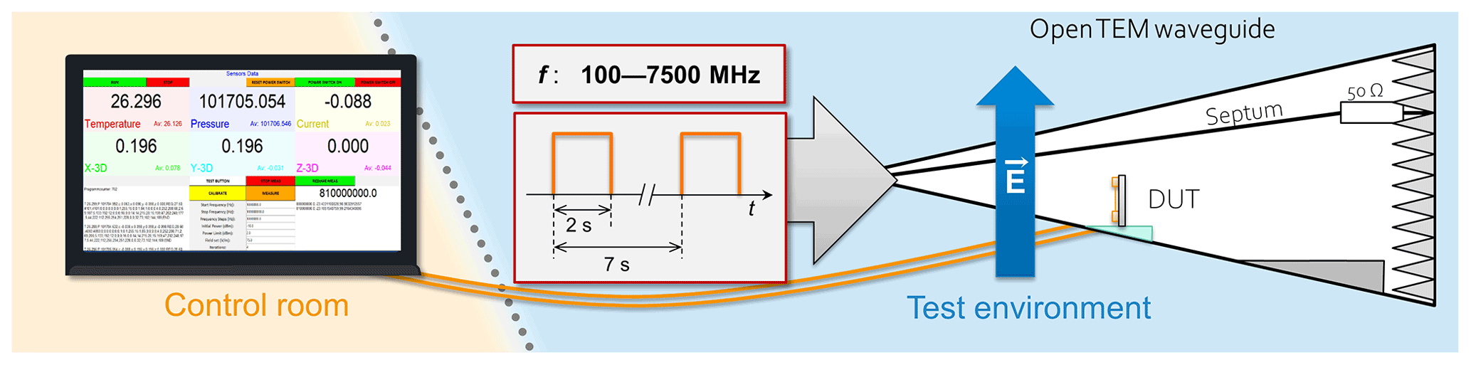
After identifying the vulnerable frequency ranges using CW signals with the same test methodology described in (Cesbron Lavau et al., 2021), the target was illuminated with pulse signals. After a calibration of the desired field strength measured with an E-field probe, the measurements were carried out by frequency scanning with a step of 10 MHz. In order to observe the behaviour of the sensors under IEMI exposure and compare it with normal conditions, the illumination was stopped for around five seconds between frequency steps as described in Fig. 2. Different pulse parameters were compared and the results are presented in the Sect. 3.
2.2 Diagnostics
During the IEMI tests, four types of errors were observed using the same monitoring software as described in Cesbron Lavau et al. (2021):
-
Loss of data under exposure: it occurs when some frames are lost: one sensor stops sending data during the duration of the exposure. The microcontroller and the other sensors are still sending correct data.
-
Loss of data link requiring restart: more critical as no more data is received by the microcontroller from the sensors, the sensors have to be restarted in order to setup again the connection with the microcontroller.
-
Raw sensor value out of tolerance: the raw sensor values are measured in real time and compared to the values when no exposure, the third error is triggered in case of values out of tolerance. This tolerance depends on the sensors and their data resolutions.
-
Sensor status error: the sensors can also send some status error codes instead of raw data such as failed initialisation, bus, frame or unknown errors, the fourth error occurs when it happens and can occur simultaneously with other errors.
Between measurements, no significant deviations were noticed; all the observable effects induced by IEMI were repeatable for the same RF parameters.
3.1 Pulse Measurements
The susceptibility figures in this paper are structured as follows: the frequency is plotted on the abscissa, the elctrical field strength is plotted on the ordinate. The markers represent the individual failures observed at a given test frequency with the description and affiliation given in Table 1.
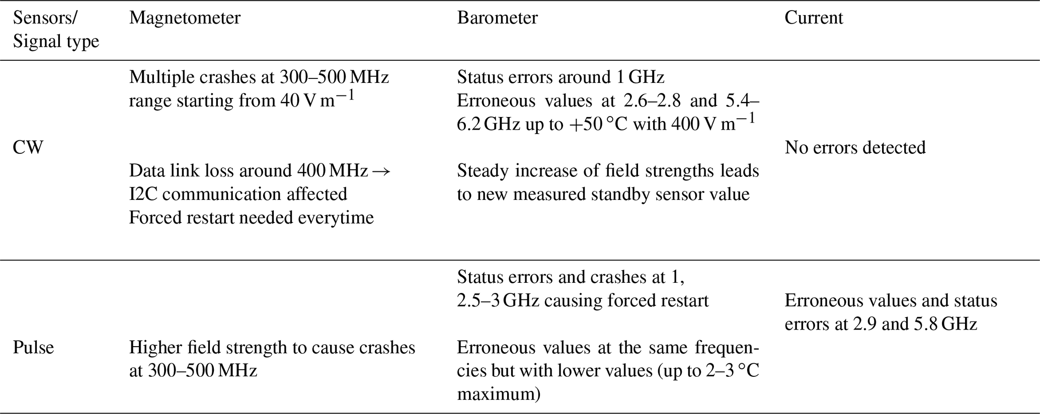
Table 1Summary of the main differences between CW and pulse signals.
Results are presented for different pulse parameters in the range 0.1 to 7.5 GHz. These failures in the next graphs are for all the three sensors and for the three tested DUT orientations.
Regardless of the DUT orientation, typical errors are observed such as erroneous sensor data, data communication being disrupted, as well as a complete freeze of all processes causing a forced restart of the system for the three different orientations and different pulse paramaters as shown in Figs. 3–5. Five different frequency ranges can be identified on these plots. In the frequency range 300–500 MHz, mostly communication erros (status and data/link lost) are observed and they are concerning exclusively the magnetometer sensor with status errors indicating a frame or bus errors. In the frequency range around 1 GHz, loss of data, values and status erros are observed, concerning mostly the barometer sensor. Between 2.5 and 3.2 GHz, changes in indicated temperature and pressure values are recorded with the barometer error, while status errors are uncommon and are due to the current sensor. Most of the erroneous values in the 5.5–6.2 GHz and around 7.5 GHz comes from the barometer sensor and presented more in details in Sect. 3.2.2, the rest of these errors are from the current sensor and are discussed in Sect. 3.2.3.
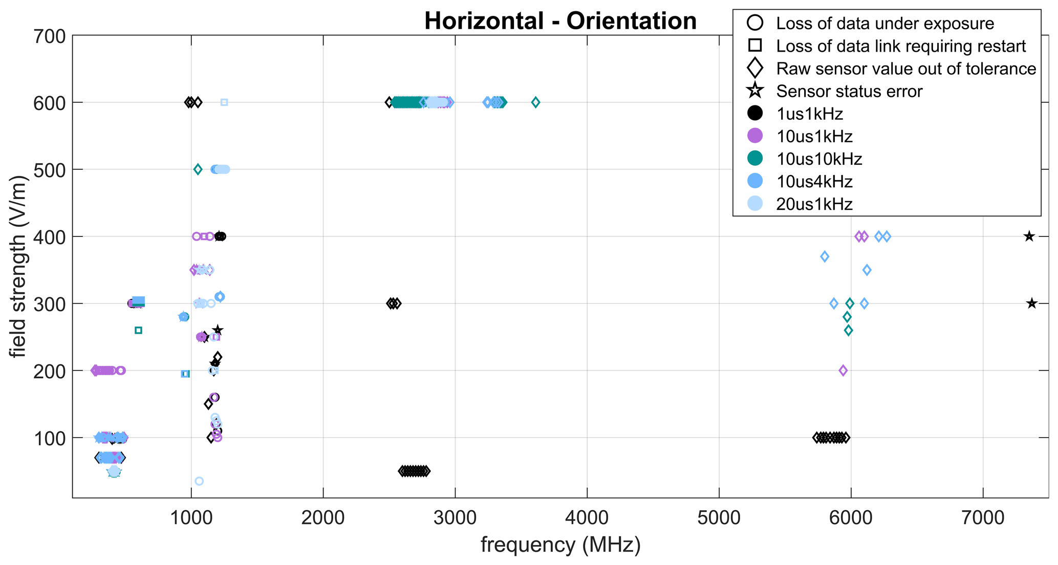
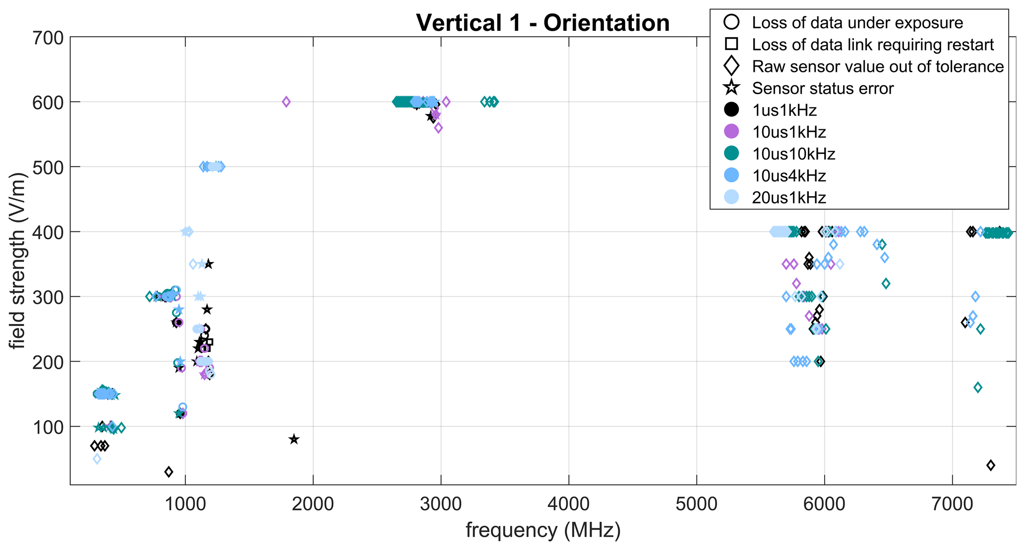
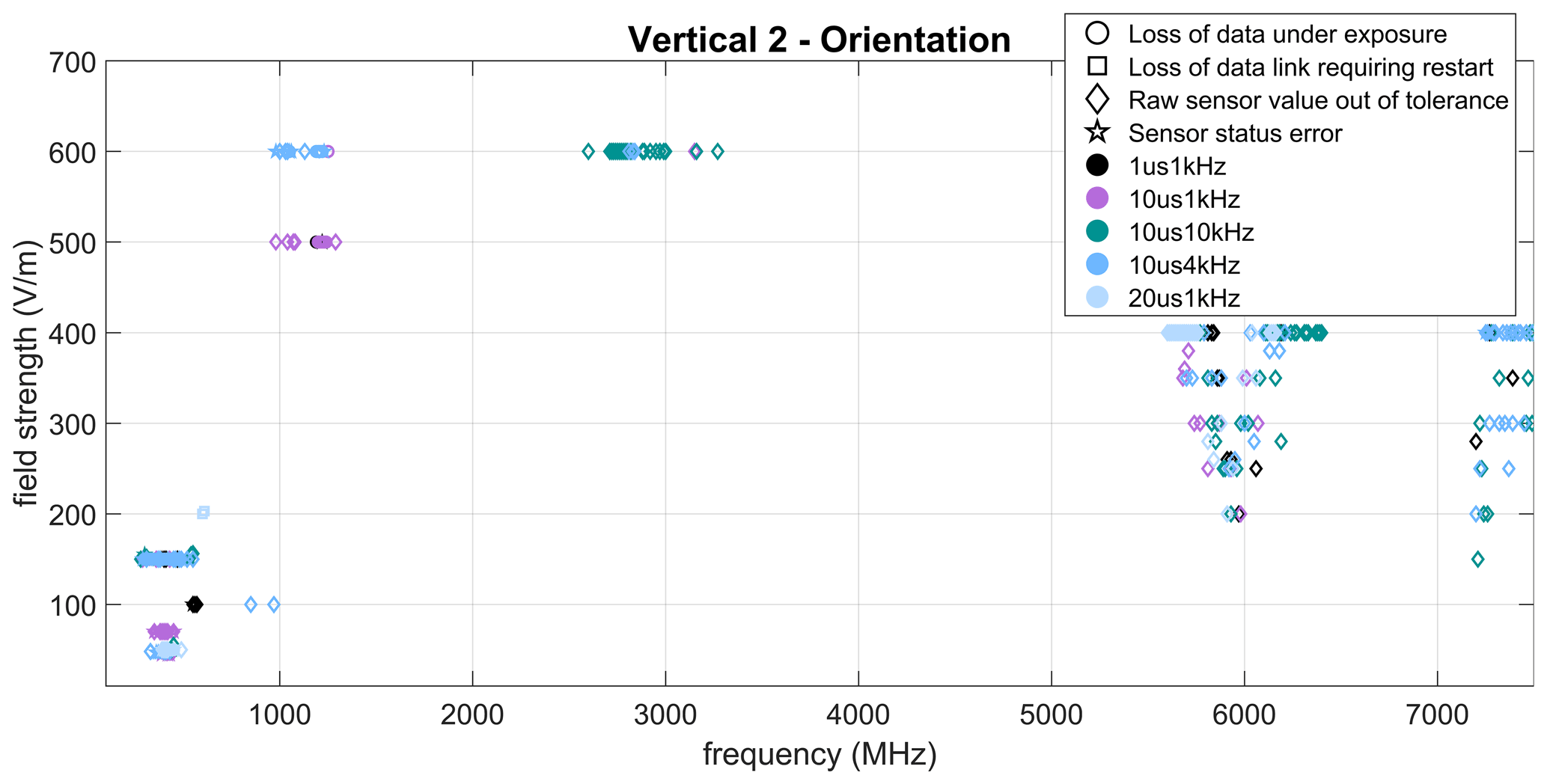
Based on these three plots, the type of pulses has no significant influence on the type of errors: the frequency or the field strength are the two most important parameters. More details regarding the influence of pulse parameters will be presented in the Sect. 3.2.
The orientation also seems to have an influence on the susceptibility. For example, at the 1 GHz range, most errors occurred when the orientation was Horizontal and Vertical 1. The PCB wires and the other components on the board (pull-up resistors, capacitors) between the sensors and the communication ports to the microcontroller were not protected during these experiments and more errors appeared at the DUT orientation with these wires parallel to the electrical field (highest coupling). However, further experiments are required to verify this hypothesis.
Another comparison of the different orientations reveals that even the vulnerable frequencies are similar, some orientations seem to be more vulnerable. In the 6 GHz range, more errors occur for both vertical orientations and those errors are very similar. The footprint of the barometer sensor (sensor which were the most influenced in these frequency ranges) is indicating similarities in the internal geometry with length and width. Further research on the footprint and hardware of these sensors will have to be conducted in order to verify the possible coupling paths.
3.2 Comparison between Pulse and CW
The next section of the research was concerned with the comparison between CW and pulse signals. A summary of the main errors observed during the measurements is shown in Table 1 and compared with the results with CW signals presented in the EMC Paper (Cesbron Lavau et al., 2021).
As shown in the table above, there were significant differences between pulse modulated and continuous-wave signals: errors leading to a crash or status errors required a higher power level threshold using pulse modulated signals and the results indicate that the pulse length had a higher influence than the pulse period. Regarding erroneous sensor data, CW signals lead to higher data variations whereas more errors appeared with PM signals and the modulation was also noticeable in the sensor data variations. Finally, while there was no observed influence on the current sensor with CW signals, erroneous values and status errors were measured at some frequencies using pulse modulated signals.
3.2.1 Magnetometer
During this study, no significant differences in effects have been observed between the pulse and the CW measurements. The analysis of log files is not bringing more information on the crashes, except that the status errors are indicating either a frame or a bus error. A more detailed analysis would require monitoring of the I2C ports (both Serial Data Line (SDA) and Serial Clock Line (SCL)) in order to observe the timing diagram and detect protocol issues if any were to occur.
3.2.2 Barometer
Regarding the barometer sensor, the raw measured temperature and pressure were influenced by the different signal parameters: CW or pulse and comparing the next plots are showing the behavior of the measured temperature in the range 5.9 to 6 GHz with a field strength of 400 V m−1. The measurement methodology was described in Sect. 2.1 and the blue parts represent the RF exposure during two seconds.
From the graphs in Fig. 6, it can be seen that there are only erroneous values during exposure. What stands out in the plots is that a startup peak appears in all cases, there is only a different order of magnitude with CW signals: a variation of around 20 ∘C. From the chart, it can be seen that the pulse parameters (width or repetition rate) have different influences on the recovery and the peak of the indicated temperature: a shorter pulse width (for example with 1 µs) is leading to a narrower peak and a higher pulse repetition rate (for example 10 kHz) led to a similar behavior to CW qualitatively, not quantitatively. It also indicates that the recovery of the indicated temperature is better for smaller duty cycle or also shorter pulses. Moreover, the relationship between the pulse width and pulse repetition rate (PRR) on recovery shows that for higher PRR the pulse width becomes less important. The analysis of the data registers is also showing that no status errors were recorded, meaning that these changing sensor values could remain undetected by the user. Further research with different time scales by increasing the RF exposure should be undertaken to investigate the recovery of the indicated sensor data.
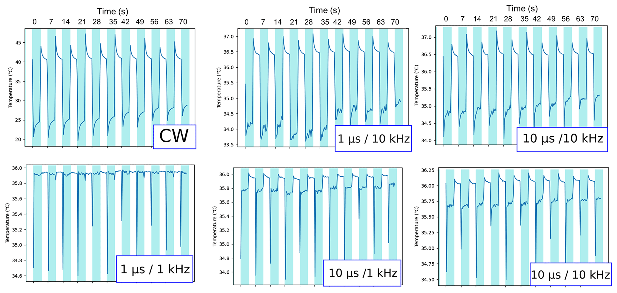
In the EMC Europe 2021 Paper (Cesbron Lavau et al., 2021), experiments indicate that it could be possible to adapt the parasitic signal to manipulate the temperature accordingly. We have seen in Fig. 6 that pulse signals could also generate a peak behaviour in the indicated temperature. One could wonder if the hysteretic behaviour found using CW signals can be achieved using short pulses and which field strength it would require.
3.2.3 Current Sensor
Whereas there was no observed influence on the current censor with CW signals, erroneous values and status errors were measured at some frequencies using pulse modulated signals as shown in Fig. 7. The frequency range on these graphs is 5.6–6.05 GHz for a constant field strength and as previously the time is in the abscissa with the current value indicated by the sensor in the ordinate. It is apparent from these plots that the pulse repetition rate has a direct influence on the sensors, causing both erroneous values and status errors.
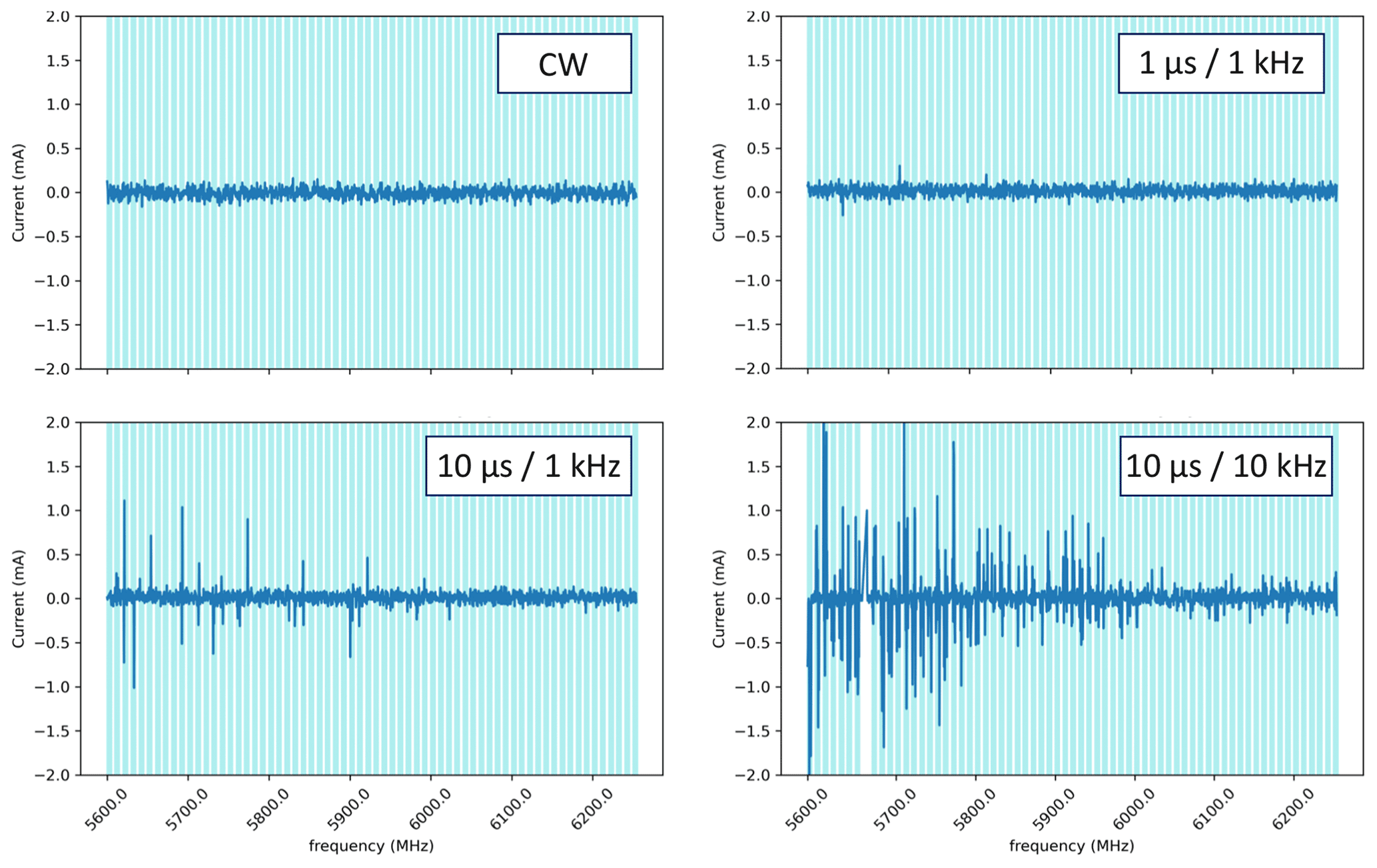
Further studies with different time scales should be carried out to determine whether the peaks in values are related to the effect of a resonance frequency in the circuit or the SPI communication clock.
Prior work has documented the effects of IEMI on embedded systems such as UAVs, smartphones, cars or smart devices. The effects are well documented and it raised the awareness of this threat. Much research in recent years has focused on analysing the risks in order to find protective measures. However, most of these studies have been focused on the entire system and not specifically on sensors. The aim of the present research was to investigate the effects of IEMI on stand-alone sensors, removing the redundancy of sensor data, one of the protective measures against attacks on sensors.
This study has identified a variety of effects regarding the deliberate manipulation of sensor readings using pulse modulated signals: erroneous sensor data, loss of data communication, sensor status errors and also a complete freeze of all processes causing a forced restart of the system. These errors have been compared with the ones observed using CW signals and are similar, the main difference is the signal parameter required to trigger these types of errors: a higher field strength for example. One of the more interesting findings to emerge from this study is that pulse parameters have a direct impact on the behaviour of the indicated sensor values: different pulse parameters (width or repetition rate) will delay the recovery of the correct sensor value and this can be used by an attacker. Compared with the hysteretic behaviour found in the paper presented in EMC Europe 2021, even after an attack the indicated sensor value might never go back to normal until a restart.
The generalisability of these results is subject to certain limitations. PCB wires between the sensors and the communication ports to the microcontroller were not protected during these experiments and more errors, especially the communication errors, appeared at the DUT orientation with these wires parallel to the electrical field (highest coupling). The loss of data communication between the microcontroller and the sensor might be caused by this coupling path. Protecting this possible coupling path will lead to a better understanding of the sensor vulnerability. Moreover, the sensors used are Commercial-off-the-Shelf sensors and are used in different applications but the hardware between the same types of sensors may differ. In order to identify possible coupling paths and general protection measures, results have to be repeatable with other similar sensors and future work will therefore focus on other similar temperature or barometer sensors for example.
Sensors are the key to many systems, which rely on the information provided. InfoSec is needed in order to ensure the availability and the integrity of the sensors. Investigating the vulnerability of sensors under IEMI will lead to a better understanding of the phenomena occurring at the physical layer of the sensors, so that suitable protection measures can be taken against those type of attacks.
Due to company internal confidentiality agreements, the source code is not freely accessible. However, we will be happy to provide the details required for this publication on request.
Due to company internal confidentiality agreements, the data is not freely accessible. However, we will be happy to provide the details required for this publication on request.
LCL developed the experiments, collected the data and wrote this paper. MS and PK have assisted in the analysis of the data and the finalization of the paper.
The contact author has declared that none of the authors has any competing interests.
Publisher’s note: Copernicus Publications remains neutral with regard to jurisdictional claims in published maps and institutional affiliations.
This article is part of the special issue “Kleinheubacher Berichte 2021”.
The authors would like to thank the U. R. S. I. Kleinheubacher Conference for the opportunity to publish this paper in the open-access journal Advances in Radio Science.
This open-access publication was funded by the RWTH Aachen University.
This paper was edited by Frank Gronwald and reviewed by Jens Werner and one anonymous referee.
Bäckström, M. G. and Lövstrand, K. G.: Susceptibility of Electronic Systems to High Power Microwaves: Summary of Test Experience, IEEE T. Electromagn. C., 46, 396–403, 2004.
Cesbron Lavau, L., Suhrke, M., and Knott, P.: Susceptibility of Sensors to IEMI Attacks, in: IEEE International Joint EMC/SI/PI and EMC Europe Symposium, Raleigh, NC, USA, 26 July–13 August 2021, https://www.doi.org/10.1109/EMC/SI/PI/EMCEurope52599, 533–537, 2021.
Del Pozo, S. M., Standaert, F.-X., Kamel, D., and Moradi, A.: Side-Channel Attacks from Static Power: When Should We Care? in: Proceedings of the 2015 Design, Automation & Test in Europe Conference & Exhibition, EDA Consortium, San José, CA, USA, 9–13 March 2015, 145–150, https://doi.org/10.7873/DATE.2015.0712, 2015.
Esteves, J. L., Cottais, E., and Kasmi, C.: Unlocking the Access to the Effects Induced by IEMI on a Civilian UAV, in: International Symposium on Electromagnetic Compatibility (EMC Europe), Amsterdam, The Netherlands, 27–30 August 2018, 48–52, https://doi.org/10.1109/EMCEurope.2018.8484990, 2018.
Fortune Business Insights: Internet of Things (IoT) Market Size, Share & COVID-19 Impact Analysis, By Component (Platform, Solution & Services), By End-Use Industry (BFSI, Retail, Government, Healthcare, Manufacturing, Agriculture, Sustainable Energy, Transportation, IT & Telecom, Others), and Regional Forecast, 2021–2028, https://www.fortunebusinessinsights.com/industry-reports/internet-of-things-iot-market-100307, (last access: 28 July 2022), 2021.
Fu, K. and Xu, W.: Risks of Trusting the Physics of Sensors, Commun. ACM, 61, 20–23, 2018.
Giechaskiel, I. and Rasmussen, K.: Taxonomy and Challenges of Out-of-Band Signal Injection Attacks and Defenses, in: IEEE Commun. Surv. Tut., 22, 645–670, 2020.
Hasan, R., Saxena, N., Haleviz, T., Zawoad, S., and Rinehart, D.: Sensing-Enabled Channels for Hard-to-Detect Command and Control of Mobile Devices, in: Proceedings of the 8th ACM SIGSAC symposium on Information, computer and communications security, Hangzhou, China, 8–10 May 2013, 469–480, https://doi.org/10.1145/2484313.2484373, 2013.
Hoad, R., Carter, N. J., Herke, D., and Watkins, S. P.: Trends in EM Susceptibility of IT Equipment, IEEE T. Electromagn. C., 46, 390–395, 2004.
Kune, D. F., Backes, J., Clark, S., Kramer, D., Reynolds, M., Fu, K., Kim, Y., and Xu, W.: Ghost talk: Mitigating EMI Signal Injection Attacks against Analog Sensors, in: Proc. IEEE Symp. Security Privacy, Berkeley, CA, USA, 19–22 May 2013, 145–159, https://doi.org/10.1109/SP.2013.20, 2013.
Lubkowski, G., Lanzrath, M., Cesbron Lavau, L., and Suhrke, M.: Response of the UAV Sensor System to HPEM Attacks, in: International Symposium on Electromagnetic Compatibility – EMC Europe, Rome, Italy, 23–25 September 2020, 1–6, 2020.
Maiti, A., Jadliwala, M., He, J., and Bilogrevic, I.: (Smart)Watch Your Taps: Side-Channel Keystroke Inference Attacks using Smartwatches, in: Proceedings of the 2015 ACM International Symposium on Wearable Computers, Osaka, Japan, 7–11 September 2015, 27–30, https://doi.org/10.1145/2802083.2808397, 2015.
Nahapetian, A.: Side-Channel Attacks on Mobile and Wearable Systems, in: Consum. Comm. Network., Las Vegas, NV, USA, 9–12 January 2016, 243–247, https://doi.org/10.1109/CCNC.2016.7444763, 2016.
Nitsch, D., Camp, M., Sabath, F., Haseborg, J. L., and Garbe, H.: Susceptibility of Some Electronic Equipment to HPEM Threats, IEEE T. Electromagn. C., 46, 380–389, 2004.
Parfenov, Y. V., Zdoukhov, L. N., Radasky, W. A., and Ianoz, M.: Conducted IEMI Threats for Commercial Buildings, IEEE T. Electromagn. C., 46, 404–411, 2004.
Radasky, W. A., Baum, C. E., and Wik, M. W.: Introduction to the Special Issue on High-Power Electromagnetics (HPEM) and Intentional Electromagnetic Interference (IEMI), IEEE T. Electromagn. C., 46, 314–321, 2004.
Richelli, A.: EMI Susceptibility Issue in Analog Front-End for Sensor Applications, J. Sensors, 2016, 1–9, https://doi.org/10.1155/2016/1082454, 2016.
Schlegel, R., Zhang, K., Zhou, X.-Y., Intwala, M., Kapadia, A., and Wang, X.: Soundcomber: A Stealthy and Context-Aware Sound Trojan for Smartphones, Proceedings of the 18th Annual Network and Distributed System Security Symposium (NDSS), San Diego, California, USA, 6–9 February 2011, 11, 17–33, 2011.
Sikder, K., Aksu, H., and Uluagac, A. S.: 6thsense: A Contextaware Sensor-based Attack Detector for Smart Devices, in: 26th USENIX Security Symposium, Vancouver, BC, 16–18 August 2017, 397–414, https://doi.org/10.48550/arXiv.1706.10220, 2017.
Son, Y., Shin, H., Kim, D., Park, Y., Noh, J., Choi, K., Choi, J., and Kim, Y.: Rocking Drones with Intentional Sound Noise on Gyroscopic Sensors, in: USENIX Security, Washington DC, USA, 12–14 August 2014, 881–896, 2015.
Subramanian, V., Uluagac, S., Cam, H., and Beyah, R.: Examining the Characteristics and Implications of Sensor Side Channels, in: IEEE ICC, Budapest, Hungary, 9–13 June 2013, 2205–2210, https://doi.org/10.1109/ICC.2013.6654855, 2013.
Trippel, T., Weisse, O., Xu, W., Honeyman, P. and Fu, K.: WALNUT: Waging Doubt on the Integrity of MEMS Accelerometers with Acoustic Injection Attacks, in: 2017 P. IEEE S. Secur. Priv. (EuroS&P), Paris, France, 3–18, https://doi.org/10.1109/EuroSP.2017.42, 2017.
Tu, Y., Rampazzi, S., Hao, B., Rodriguez, A., Fu, K. and Hei, X.: Trick or Heat? Manipulating Critical Temperature-Based Control Systems Using Rectification Attacks, in: ACM Conference on Computer and Communications Security (CCS), London, UK, 11–15 November 2019, 2301–2315, https://doi.org/10.1145/3319535.3354195, 2019.
Ware, D. A.: Effects of Intentional Electromagnetic Interference on Analog to Digital Converter Measurements of Sensor Outputs and General Purpose Input Output Pins, MS thesis, Utah State University, https://doi.org/10.26076/dafa-c720, 2017.
Yan, C., Shin, H., Bolton, C., Xu, W., Kim, Y. and Fu, K.: SoK: A Minimalist Approach to Formalizing Analog Sensor Security, in: P. IEEE S. Secur. Priv., San Francisco, CA, USA, 18–21 May 2020, 233–248, https://doi.org/10.1109/SP40000.2020.00026, 2020.
Zhang, Y. and Rasmussen, K. : Detection of Electromagnetic Interference Attacks on Sensor Systems, in: P. IEEE S. Secur. Priv., San Francisco, CA, USA, 18–21 May 2020, 203–216, https://doi.org/10.1109/SP40000.2020.00001, 2020.
Zhuang, L., Zhou, F., and Tygar, J. D.: Keyboard Acoustic Emanations Revisited, ACM T. Inform. Syst. Se., 13, 3, https://doi.org/10.1145/1609956.1609959, 2009.