 | 21 Mar 2023
Antenna Setup for Future Joint Radar-Communications – Characteristics and Mounting Positions
Maximilian Lübke
Jonas Fuchs
Anand Dubey
Martin Frank
Norman Franchi
Fabian Lurz
The development of millimeter wave systems is driven by the strong trend toward new communications generations and especially by the emerging joint radar and communications design approach. Safety-critical applications like platooning or intersection assistance will significantly benefit from the combination of sensing and communications. While radar performs a channel measurement and thus, needs a wide field of view (especially in city/intersection scenarios), communications aims to minimize the interference for other not addressed receivers (e. g. in a platoon) by a focused antenna design. The proposed work extends the analysis of the influence of various antenna positioning for a typical automotive scene by taking also different characteristics (antenna gain, half power beamwidth, and sidelobe level) into account. Hereby, it is mandatory to investigate the communications and sensing performance simultaneously. The positions at the front bumper – typical for radar sensors – and especially at the left mirror convinced regarding the vehicular communications as well as the sensing behaviour. Applying focused antennas is promising, however, has also limits if the signals are not received out of the main beam but out of the sidelobes, resulting in a critical communications performance. Thus, beam steering is recommended to be applied in the future.
- Article
(1455 KB) - Full-text XML
- BibTeX
- EndNote


Intelligent transportation systems, enabling communications between vehicles in the context of info-/entertainment but mainly addressing safety applications, are highlighted to be one of the future key technologies (Liu and Masouros, 2021). As an extension to the already existing sub-6 GHz standards like Long-Term Evolution (LTE) and Wireless LAN (WLAN) (Sommer and Dressler, 2014), millimeter waves (mmWaves) get more and more attention, due to the high available bandwidth and data rates.
In the mmWave frequency bands, safety applications are the main application field of radar sensors. Lane change assistance and adaptive cruise control systems have become an indispensable part of modern cars and trucks (Waldschmidt et al., 2021). However, radar signals are limited in their range and resolution due to their waveform characteristics (e.g. carrier frequency, bandwidth, output power, receiver dynamic) as well as the underlying measurement principle of the primary radar. Meanwhile, the combination of both technologies i. e. communications and sensing can be advantageous, as communications will enable to transmit and receive information beyond the field of view of the own or even beyond the neighbouring vehicles (Dokhanchi et al., 2021; Feng et al., 2020).
To combine these, several approaches are being discussed in the research community regarding co-design, cooperation, or co-existence (Chiriyath et al., 2017; Ma et al., 2020). This will need an optimized physical layer design, as both can negatively affect each other, e.g. a large mutual radar interference could distort the communications link (Singh et al., 2021). In consequence, a co-design/-existence will also require discussing the antenna design and placement, as there is a conflict between the optimization of communications and radar antenna systems. Whereas communications uses focused beams to reduce interference for non-addressed listeners, radar sensor must have a wide field of view to measure the channel properly, such that traffic participants like vulnerable road users are not miss detected. The proposed work is an extension to our previously published work in the Kleinheubach Conference (Lübke et al., 2021b), where we evaluated and compared various antenna mounting positions (roof, bumper, mirror) regarding the resulting radar sensing as well as communications performance. In this work, however, we go a significant step further by additionally investigating the influence of the chosen antenna characteristics, like antenna gain, half power beamwidth, or the sidelobe level of various antennas. Besides, we extend our previous work by analysing several time steps regarding multiple metrics, including power delay profiles, delay spreads, cumulative distribution functions for the communications, and rating the sensing performance based on the obtained range-Doppler maps. In consequence, our extended key contributions are:
-
we still investigate the propagation effects for typical rural traffic scenes via the 3D-Ray-Tracing Tool WinProp, Altair;
-
we extend our previous work by comparing various antennas with different antenna characteristics (antenna gain, sidelobe level, half power bandwidth) for varying mounting positions; and
-
we evaluate the resulting sensing as well as vehicular communications performance in the context of a future frequency modulated continuous wave (FMCW) joint radar and communications system, respectively.
Antennas in the automotive context have great importance, addressing various applications. Besides well-known positions like the roof, addressing GPS (Global Positioning System) or FM (frequency modulation) radio (Yang et al., 2020; Liu et al., 2019), radar sensors are mounted at the front and back bumper generally (Patole et al., 2017). In the future, even more antennas will be required, e. g. to provide a 360∘ radar sensor view for autonomous driving, while in the context of communications massive Multiple Input Multiple Output (MIMO) and increased data rates will also demand a higher amount of antennas (He et al., 2019).
But, every application needs its own optimized design. As vehicular communications and especially the joint-radar-communications is aiming to build up a co-design or even a co-existence, which consequently leads to a shared antenna setup, an optimized antenna design is searched for. The typical radar position at the bumper has drawbacks, e. g. in case of a light car accident, the position is prone to be damaged. Additionally, dirt is collected at the bumper, which has a negative influence on the propagation of electromagnetic waves (Araghi et al., 2020). Therefore, multiple positions at the roof top, the mirror, the rear screen, or the engine hood are discussed for both radar (Araghi et al., 2020) and communications (Winkler et al., 2020). In the following section, three main positions i.e. the roof, left mirror (the mirror facing the other vehicles) and front bumper are evaluated regarding their communications and radar performance in a typical rural traffic scenario. Due to the lack of suitable measurement campaigns and channel models in the literature (He et al., 2020), the scene is analysed with a commercial 3D-ray-tracing software WinProp, Altair (Altair, 2022), which is validated for the mmWave frequencies according to Lübke et al. (2021a, c); Nguyen et al. (2014); Zhang et al. (2015). The considered scene, the corresponding simulation configurations and the chosen metrics are described below.
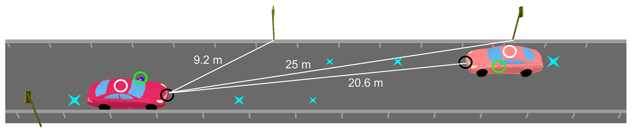
Figure 13D-model of the rural traffic scene reconstructed in WinProp (v.2021.0.3). Three antenna positions are evaluated for both, the communications and radar use case and highlighted in white (roof), green (mirror), and black (bumper) circles. The solid white lines indicate the distances between the main obstacles and the radar unit (here as an example mounted on the bumper). Additional distance due to height differences must be taken into account. The blue stars mark the different evaluated time steps [0.5 s:0.5 s:2 s], depicted at t=1 s.
2.1 Simulation environment – WinProp configuration
Due to the deterministic character of the 3D-ray-tracing simulation tool WinProp, the considered scene is reconstructed with a high detail level. Material characteristics (permeability, permittivity, conductivity, scattering matrix, and thickness) are defined for the carrier frequency of 77 GHz, as the computation is based on the Fresnel equations, the geometrical theory of diffraction and the uniform theory of diffraction, respectively. In extension to our previous works (Lübke et al., 2020, 2021b) a rural line-of-sight (LOS) scene is now analysed regarding the applied antennas as depicted in Fig. 1. Both cars have the same length of 5 m and a width of 1.9 m, whereas the poles of the street lamps have a diameter of 0.1 m and a starting height of the sign of 2.2 m. Moreover, the diamond-shaped street sign has a diagonal of 1 m. The traffic signs and vehicle bodies next to the guardrails are adapted to a conductivity σ of 428 kSm−1 according to Lähteenmäki (1994), respectively. Besides, the relative permittivity and the relative permeability are chosen as εr=1 and μr=20, whereas the material parameters of the street are σ=0.1 Sm−1, εr=8 and μr=1. On a rural street, two vehicles are driving with a speed of 10 m s−1 towards each other. The left car transmits information to the right car while detecting the environment like the included obstacles (guard rails and street signs) via an additional radar, sharing the same antenna. In this work, the antennas are always studied as pairs with the same antenna characteristics, which means that the joint radar sensing and communications system uses the same antenna array for the communications and sensing functions. However, the channel can be considered reciprocal, which means that the transmit and receive antennas are generally interchangeable, and consequently a link budget analysis is performed for different antenna characteristics.
Three different antenna positions are applied to investigate their influence: at the roof placed at a height of 1.6 m, at the front bumper at 0.5 m, and at the left mirror at 1.1 m, respectively. In extension to Lübke et al. (2021b), several antenna characteristics are evaluated, representing focused as well as broad characteristics with varying antenna gains, half power beamwidths (HPBW) as well as sidelobe levels (SLL). The orientation of the antennas agrees with the driving direction of the vehicles on which they are mounted. Furthermore, the applied antennas at the transmitter as well as at the receiver have always the same pattern.
In our previous work, a focused antenna array, corresponding to a 77 GHz 2×2 patch antenna array with 12.38 dBi gain, was analysed and compared to an isotropic antenna setup. Its directivity is displayed in Fig. 2, whereby the directivity equals the gain as an efficiency of 100 % is assumed. The antenna has an SLL of −11.99 dB and an HPBW in the azimuth direction of . Overall, there is a trade-off between good focus and a wide field of view. Besides, the aforementioned 2×2 patch arrays, a 3×3 with particularly distinct sidelobes as well as a 4×4 and particularly focused 8×8 and 16×16 patch arrays are investigated. The corresponding antenna characteristics are summarized in Table 1.
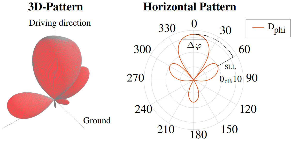
Figure 2The 3D- and horizontal directivity of the considered 77 GHz antenna. It has a sidelobe level (SLL) of −11.99 dB, and a half power beamwidth in azimuth direction of . (reprinted with permission Lübke et al., 2021b © 2021 IEEE.)
Table 1Applied antenna characteristics.
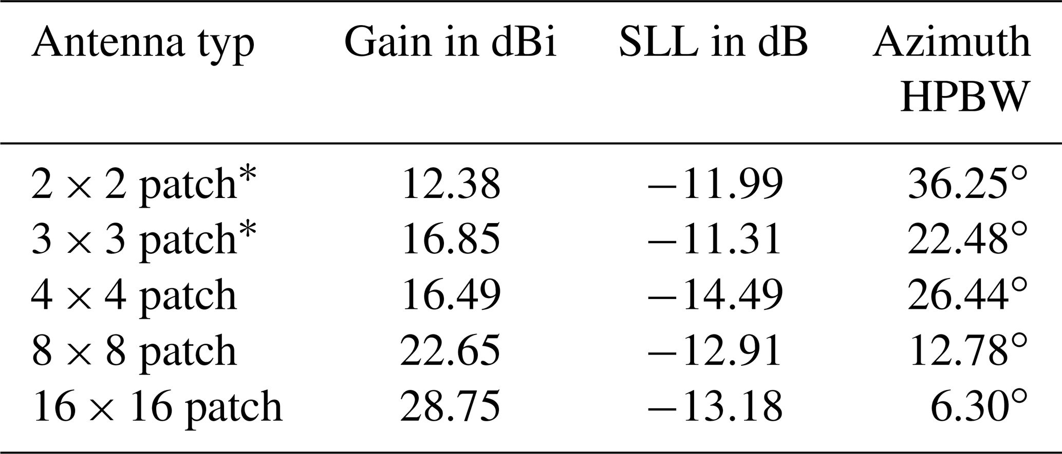
* Corresponds to antenna characteristics with particularly distinct sidelobes.
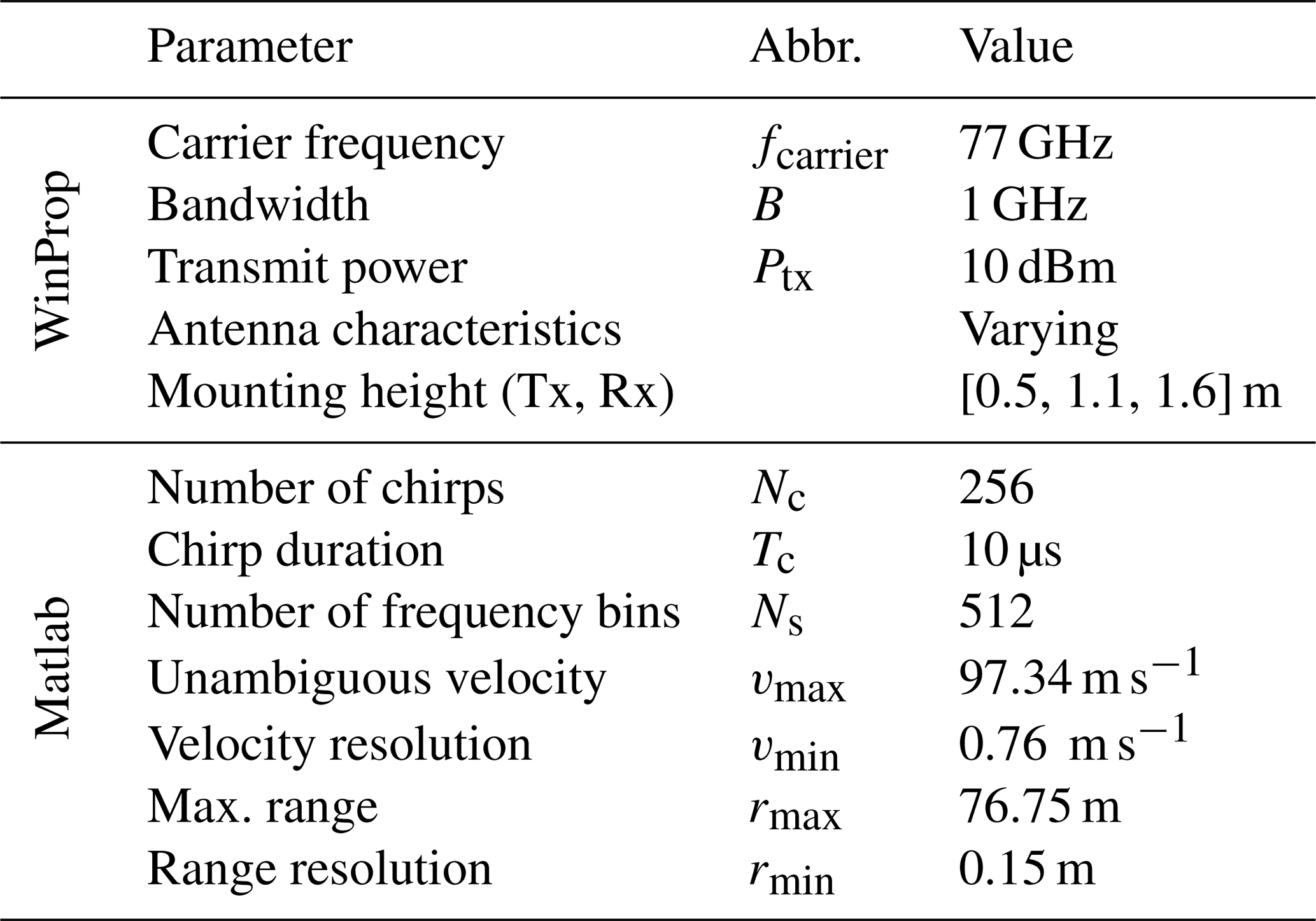
The signals are transmitted with an output power of the transmitter power amplifier of 10 dBm (plus the antenna gain) at 77 GHz. In the time-variant simulation ([0 s:0.5 s:2 s]), the computed paths are limited to 1024, including up to one transmission and three reflection paths. In the context of radar, additional paths are excluded: apart from the direct LOS path (the radar should be mono-static), reflections close to the sensor are excluded from the analysis. Besides, a dynamic range of up to 150 dB is considered, while the simulation resolution is set to 0.15 m, corresponding to a bandwidth of 1 GHz. Moreover, paths are highlighted, which do not exceed the noise power level Pn of the thermal noise floor in compliance with with a baseband bandwidth BBB of 5 MHz. A bandwidth of 5 MHz is chosen as it corresponds to two times the lowpass cutoff frequency (fcutoff=2.5 MHz) of a common FMCW-based system (Gardill et al., 2019).
Further signal parameters are configured according to a typical FMCW-based mid-range radar, which has an unambiguous range of over 75 m. The number of chirps is set to 256, the chirp duration to 10 µs and the number of frequency bins to 512, resulting in a maximal velocity of 97.34 m s−1 with a resolution of 0.76 m s−1. The applied parameters for the WinProp channel simulations as well as the parameters for the FMCW post-processing, done in Matlab, are summarized in Table 2.
2.2 Metrics
As both the radar and the communications performance are analysed, different metrics have to be used. In the context of communications, the scene is evaluated regarding the power-delay-profile (PDP) and the root mean square (RMS) delay spread τrms according to
τ corresponds to the delay, to the mean delay of the channel and Ph to the received power, respectively. Besides, the strongest received signal powers are estimated for the three antenna positions as well as for the omnidirectional antenna and the focused patch antennas, summarized in Table 1.
In addition, the cumulative density function (CDF) is evaluated, as, through the CDF, the distribution of the reception strength can be displayed for the different antenna characteristics or mounting positions. Therefore, the obtained channel information is exported from WinProp to Matlab, containing a list of the individual paths and their corresponding received power besides exemplary their delay, Doppler shift, the direction of arrival, and direction of departure. However, since the distribution of the received power is unknown, the distribution function is calculated with the help of an empirical, cumulative distribution function in Matlab.
On the other hand, the radar performance is rated based on the obtained range-Doppler (RD) maps. These maps are generated based on the simulated and post-processed in-phase and quadrature (IQ)-data, by applying a Hanning windowing function in addition to performing a 2D-Fourier transformation in Matlab.
In the IQ-data, noise is included as well, corresponding to at least the predefined Pn noise level. The detailed description of the individual processing steps and the applied configurations can be found in Dubey et al. (2021) and in Table 2, respectively.
The RD maps are then further processed (Constant False Alarm Rate detection, clustering), resulting in the final target detection (range, velocity) whose results are discussed in the next section.
In the following, the results for the communications as well as for the sensing part – assuming that they share the same hardware/antenna setup – are presented for the aforementioned antenna arrays and antenna positions.
3.1 Communications
Focusing on the scene displayed in Fig. 1, the PDPs and the RMS delay spread are analysed for the different antenna positions. Hereby, the 2×2 patch array is compared to the omnidirectional case in the first step. As an extension, the more focused patch arrays are evaluated regarding their communications performance, investigating also the CDFs over all time steps.
3.1.1 Omnidirectional and 2×2 patch arrays
The results of the 2×2 patch array transmitter-receiver pair are summarized in addition to the omnidirectional antennas (given in brackets) in Table 3.
Table 3Communications characteristics (maximum LOS and second peak power next to the RMS delay spread) for the scene, depicted in Fig. 1. For comparison reasons, the results of the 2×2 patch array and the omnidirectional one (in brackets) are shown. There are minor deviations compared to Lübke et al. (2021b), caused by adapted material characteristics (electrical conductivity).

Compared to the omnidirectional antennas, there is a significant improvement by the directional antennas as the received power increased by about 22 to 24 dB. Hereby, the difference in the LOS power for the different positions is caused by varying distances between the antenna pairs, considering the scene illustrated in Fig. 1. This results in a difference of up to 2.32 dB between the bumper and the roof (according to Friis, 1946). Besides, the τrms is decreased significantly for each (focused) antenna position, but especially for the roof position. This goes hand in hand with a decrease in observed multipath paths for focused antennas, again, particularly for the roof position.
Among the antenna positions, the roof, however, showed the worst results. Whereas the multipaths are no more dominant or are even suppressed for the left mirror and the front bumper position using the focused antenna pattern, scattering paths and multi-reflections from various obstacles, mainly caused by the guard rails left and right from the transmitting vehicle, are still prominent for the roof antenna. In the evaluated time step (t=1 s), this is not critical as most of the paths are below the thermal noise level. For later time steps >1 s and for increased antenna gains, these multipaths (clusters at 125 and 225 ns in Fig. 3) gain influence, as they are beyond the noise floor (indicated as red line) and can potentially distort the received signal.
From the communications point of view, the left mirror and the front bumper position behave similarly and can be both recommended.
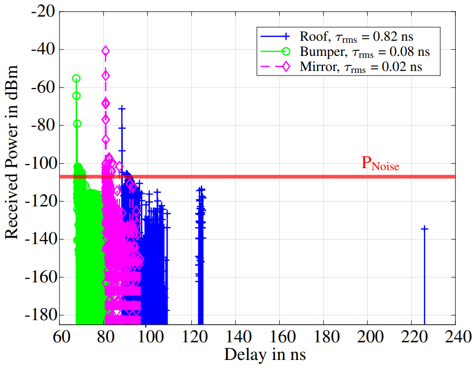
Figure 3PDP for the 16×16 patch antenna and the three evaluated antenna mounting positions. The horizontal red line corresponds to dBm.
3.1.2 Focused antennas
In general, an increase in antenna gain results in a squared rise in received power (in accordance with Friis, 1946), as the transmitter and the receiver are always chosen to have the same antenna pattern. This is ideal because the antennas are not aligned with each other but in the driving direction of their mounted vehicle. However, as the antenna gain increases, the distortions have a greater effect. In Table 4, the reviewed antenna patterns are compared for the various transmitter/receiver positions. In Fig. 3, the PDP observed at the three antenna mounting positions for the 16×16 patch antenna (28.75 dBi gain) is displayed. It has to be remarked that there is a time offset as well as an offset in amplitude due to differences in range among the mounting positions. The received power of the left mirror position dominates the others clearly (−40.7 dBm vs. −71.2 dBm and −55.2 dBm), which is discussed later. Besides, it can be seen that the roof has the most prominent distortions, whereas the bumper, as well as the mirror position, have less distortion/time clusters and, in consequence, have a lower τrms. This becomes even more apparent at higher antenna gains and at later time steps associated with shorter distances between transmitter and receiver.
Table 4Communications characteristics resulting from the different antenna characteristics for the scene, shown in Fig. 1.
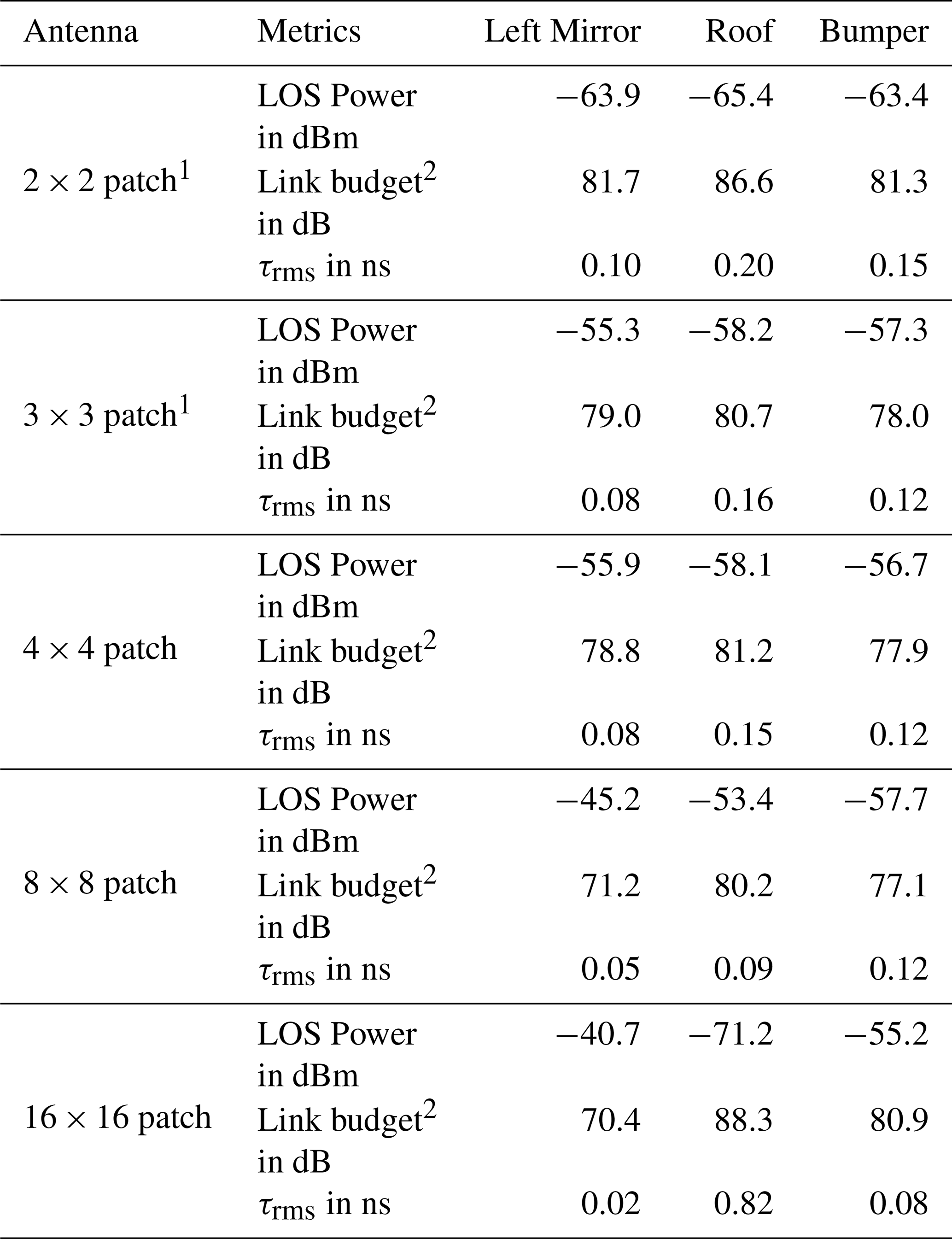
1 Corresponds to antenna characteristics with particularly distinct sidelobes. 2 Corresponds to the link budget excluding the RX antenna gain.
Besides, the RMS delay spread is further reduced for all antenna positions by applying focused antennas (increase in antenna gain as well as a decrease in HPBW): Exemplary for the left mirror from 0.1 ns for the 2×2 patch array to 0.02 ns for the 16×16 patch array, while for the roof τrms was reduced from 0.2 to 0.09 ns for the 8×8 patch array. For the 16×16 patch array, however, there is a jump in τrms to 0.82 ns as well as a significant decrease in the received LOS power. Here, it gets obvious that the focusing of the antenna is too strong, meaning it has a too low HPBW so that the LOS path is not received out of the focused beam anymore. In consequence, the received power is decreased and the distortion is increased. In the case of the 16×16 patch array, the signal is reduced by about −6 dB as compared to the 2×2 patch array, instead of an ideally expected increase of . Thus, the communications can not benefit from the antenna gain at all, which can also be seen in the PDP depicted in Fig. 3 and for the transmission path loss in Table 4. Since the transmit power is set to 10 dBm plus the corresponding antenna gain (according to Table 1), which in turn depends on the direction of departure in azimuth and elevation, it can be seen that for the 16×16 patch array a link budget of 88.3 dB means that only a marginal part of the 28.75 dBi antenna gain is considered for a receive power of −71.2 dBm. It should be noted that the given link budget only includes the transmission path loss with the antenna gain on the side of the transmitter, but does not take into account the antenna gain of the receiver. Summarized, communications is established via a sidelobe rather than the main lobe of the antenna. This confirms that the roof position shows the worst communications performance as described in the subsection before. However, also for the bumper, the received power is not increased according to the increase in antenna gain, stating that the received beam is also mainly received out of sidelobes and not out of the focused beam. Only for the mirror position, a clear augmentation in received power in addition to a significant decrease in τrms is observed.
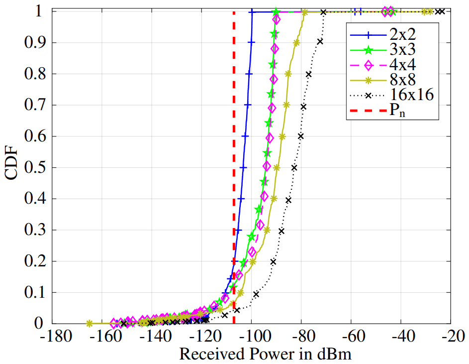
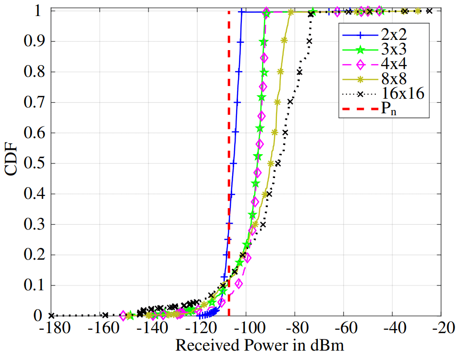
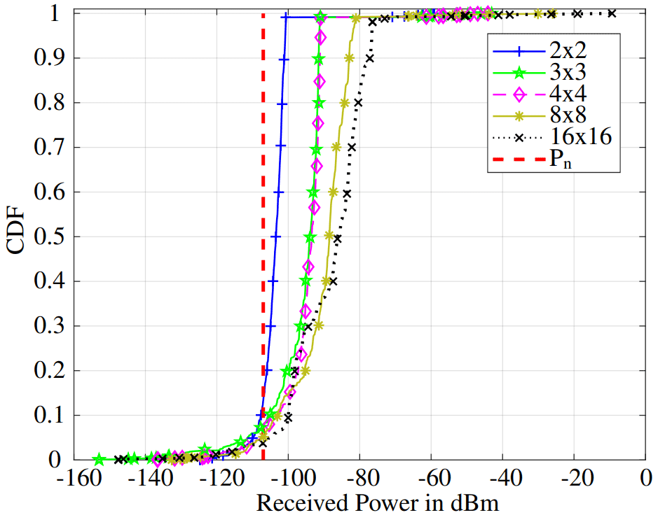
In the extension of the previous analysis of time step t=1 s, the CDFs of the varying positions and antenna characteristics are investigated and plotted in Figs. 4, 5 and 6 for all 5 time steps, respectively. The vertical red line corresponds to the noise floor equal to dBm. In general, the further to the right the distribution function is located, the higher the maximal received power and consequently, the higher the SNR. Sharp rises correspond to a high number of paths, having the same received power, which can especially be seen for all three positions for the 2×2 patch array as well as to a lesser degree for the 3×3 and 4×4 patch arrays. Besides, the CDF of 3×3 and the 4×4 almost overlap, as they only differ slightly in HPBW, antenna gain, and sidelobe level.
The CDFs of the most focused antennas (8×8 and 16×16 patch arrays), however, show significant differences in their curve characteristics compared to the aforementioned ones. Except for the bumper, the CDFs of all patches intersect for low received powers approximately at −100 dBm for the roof as well as for the mirror mounting position. This can also be seen in Table 5, where all antennas and mounting positions are evaluated regarding the amount of received signals exceeding the noise floor and the received power which marks the limit to have 99 % of the signals included. It is obvious that with an increasing antenna gain, more signals exceed the noise level for all positions. However, for the roof position, the 8×8 as well as the 16×16 patch arrays show a decrease and remain in signals exceeding, respectively. Thus, this indicates again that the antennas are too focused such that the signals are not received from the main antenna beam but from the sidelobes. Taking all time steps into account, the LOS path is not disrupted, as the difference in received power between the diverse antenna patches is nearly corresponding to the expected gain of roughly 33 dBi.
Table 5Evaluation of the CDFs of the different antennas regarding the probability to exceed the noise floor and the threshold of received power at which 99 % of the signal is detected.

* Corresponds to antenna characteristics with particularly distinct sidelobes.
Summarized, it can be seen that compared to the bumper and mirror position, the roof provided the worst result. The bumper, as well as the mirror position, are convincing, especially the mirror. It is observed that the more focused antennas are used the more the delay spread is reduced and the more the received power is increased due to the increased antenna gain. However, it has to be remarked that highly focused antennas with low HPBW induce the problem of reduced communications performance since in that case, signals are transmitted/received from the sidelobes instead of the main beam.
3.2 Radar
As for the communications, the sensing performance is first evaluated using the 2×2 patch antenna array. The results of the different mounting positions are analysed and compared to the results observed for the omnidirectional antenna setup. In the next step, the sensing performance of the more focused antennas is investigated.
Table 6Detected targets for the 2×2 patch array as well as for the omnidirectional case (in brackets) at the different antenna positions.
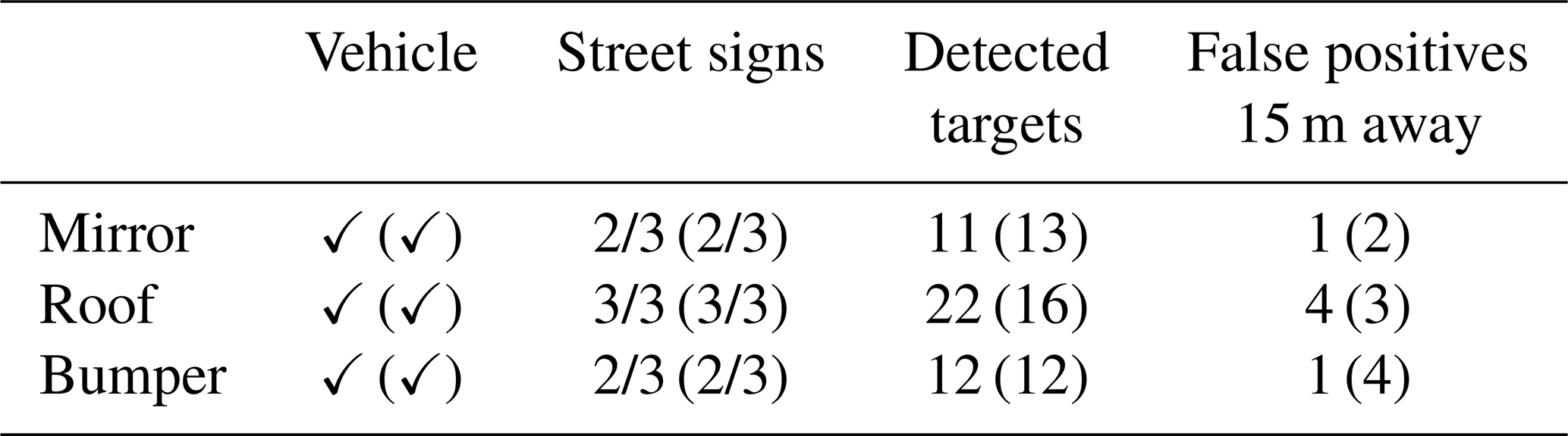
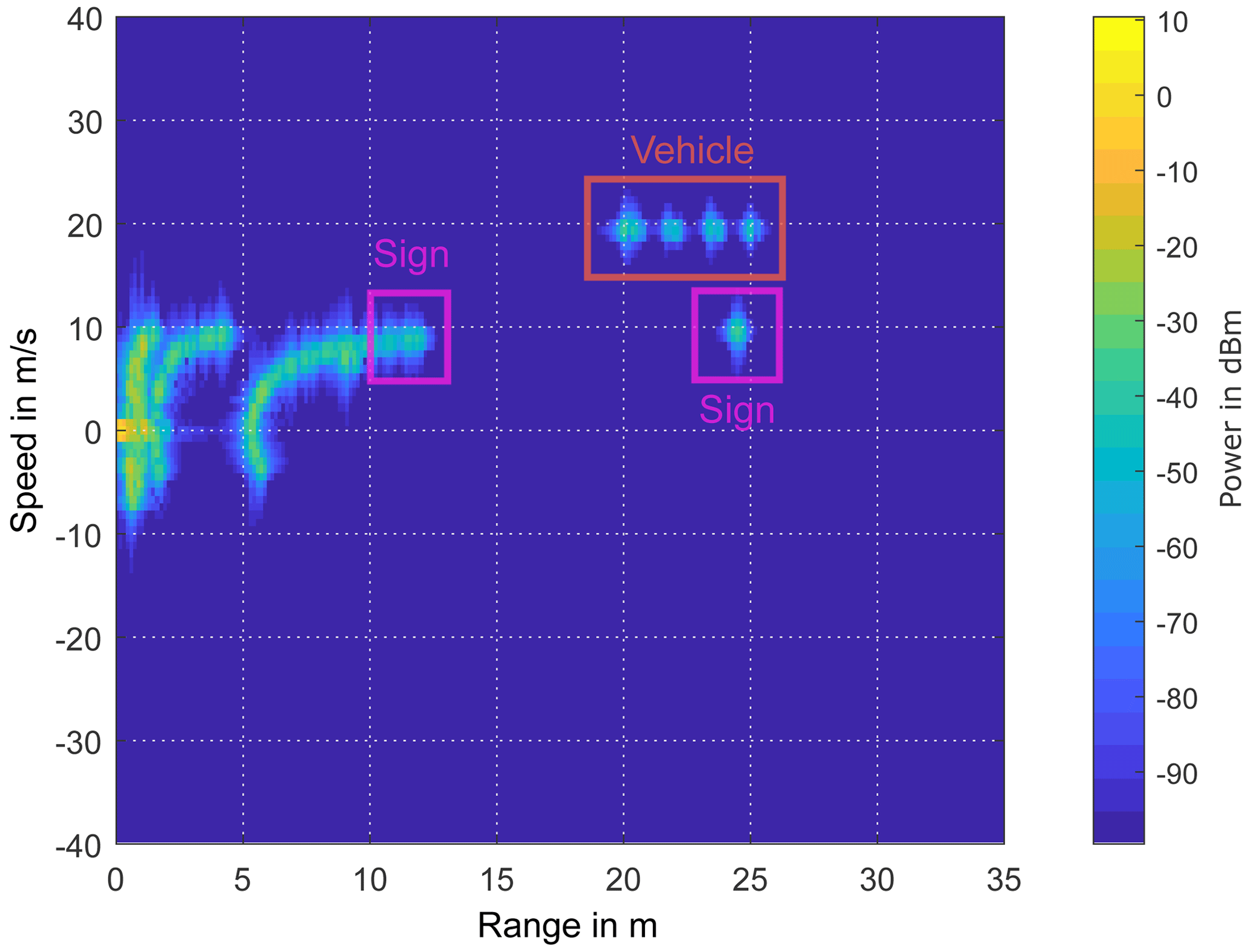
Figure 7RD map for a transceiver, mounted at the front bumper, for the scene of Fig. 1. The detection points are marked regarding the targets: the red frame corresponds to the approaching car and the magenta ones to the street signs. (reprinted with permission Lübke et al., 2021b © 2021 IEEE.)
3.2.1 Omnidirectional and 2×2 patch arrays
The results of the radar signal processing (described in Sect. 2.2) are summarized in Table 6 and cross-validated with the scene shown in Fig. 1. As in Sect. 3.1.1, the results of the omnidirectional antenna are displayed in brackets. For the sensing, the multipath, which is dominant in the omnidirectional case, does not significantly affect the target detection in contrast to the communications results. Even though the detection points of the approaching vehicle are reduced in the omnidirectional case, detection of the car is still achieved without any difficulty. However, for the left mirror and the front bumper, there are more false positive detections for ranges above 15 m (2 instead of 1; 4 instead of 1). A threshold of 15 m is considered as reflections and scattering at the guard rails dominate the RD map for lower ranges. This can be seen exemplary in the RD map, detected at the front bumper, in Fig. 7. For the roof position, there are fewer false positives for an omnidirectional antenna, as the high amount of dominant multipath is getting amplified and thus, are more dominant for the focused antennas. Therefore, the problem of multipath with respect to the roof position is also present in the radar detection context.
Due to its wide field of view, the roof position has at the same time the benefit of detecting even obstacles like the third street sign which non of the other position is capable of. Thus, in the RD map corresponding to the antenna at the front bumper, displayed in Fig. 7, only the approaching car (marked in red) and two street signs in magenta are detected. The third street sign is not detected by the sensor, however, the guard rails, with their elliptical shape, dominate in the RD map for the range below 10 m. For the mirror position, “targets”, corresponding to the nearby environment like the transceiver car itself or the nearby ground, appear more clearly in the range of 0 to 5 m. Besides, the elliptical shape gets more dominant as the guardrails are more present in the field of view. Nevertheless, both the left mirror as well as the front bumper position can be seen as equally suitable for sensing.
Table 7Overview of the detected targets for the varying antenna positions and characteristics.
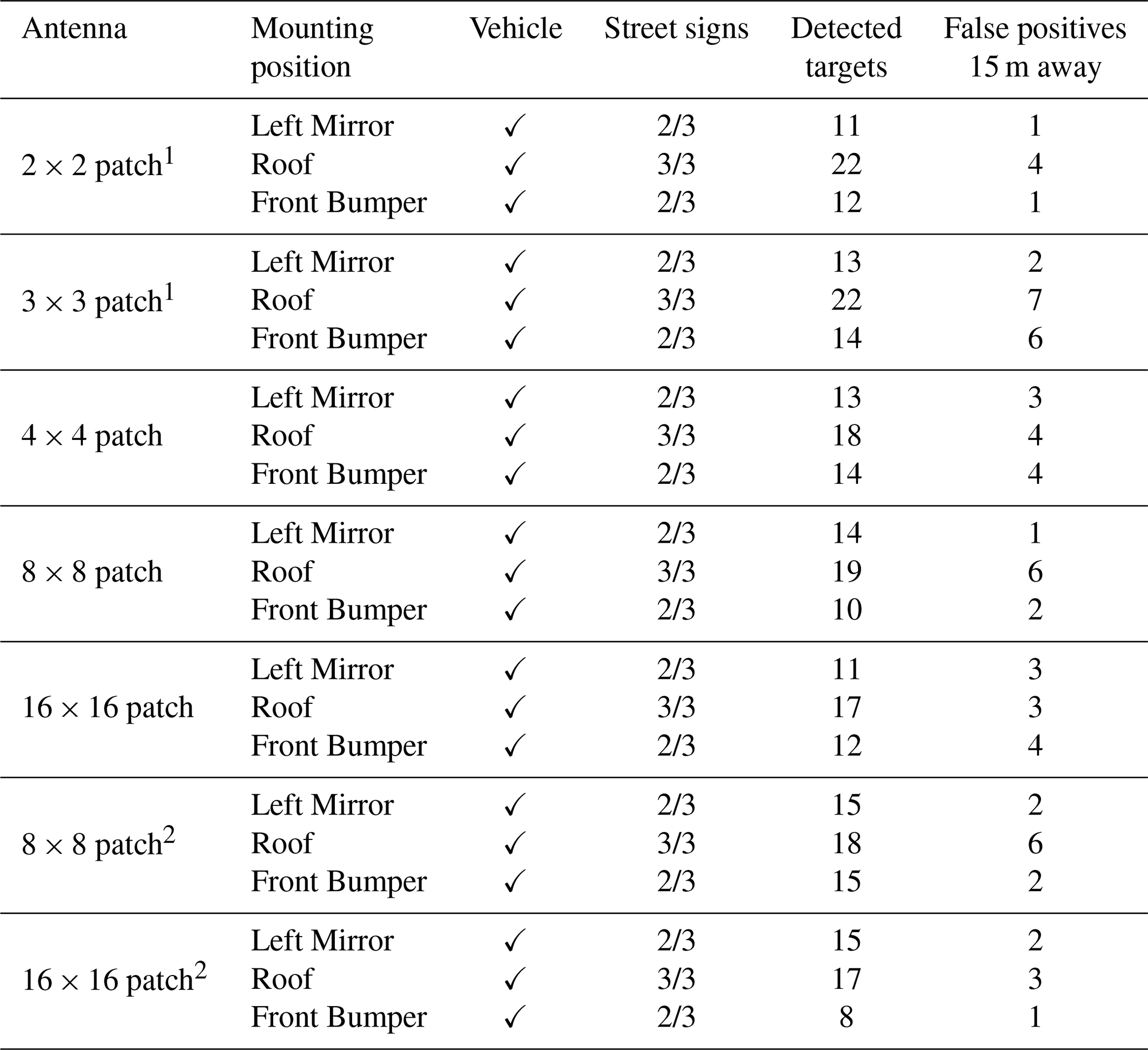
1 Corresponds to antenna characteristics with particularly distinct sidelobes. 2 Marks the radar results for the timestep 0.5 s, in contrast to the other results observed at 1 s.
3.2.2 Focused antennas
In extension to the analysis of the sensing performance of the 2×2 patch array, the performance of the more focused antennas (higher gains and less HPBW) is also investigated. The results are summarized in Table 7. Similar to the results of the previous subsection, the roof position still has the benefit to have a wide field of view, being able to detect even all three street signs, in contrast to the bumper and the mirror position. Additionally, all antenna settings are able to detect the approaching car without any problem. However, it has to be noted that the analysed scenario does not consider a complex environment, meaning that the obstacles included have high radar cross sections (RCSs) and exemplary no vulnerable road users with low RCSs are inserted. Overall, the detected targets are roughly constant for varying antenna characteristics, whereby the roof always has the highest number of detected targets and mostly also the most false positives in a distance of 15 m. The peak in false positives is observed with the 3×3 and 8×8 patch array, mounted at the roof, with 7 and 6 falsely assumed targets, respectively. To validate this, an additional time step at 0.5 s is analysed and highlighted in Table 7 as “2”. Also here, the 8×8 has the highest amount of false positives, whereas for 16×16 the number is reduced but is still at a high level. Apart from that, the bumper position suffers from high false positives, mainly for minor focused antennas (peaking to 6 false positives for the 3×3 patch array), whereas for the focused ones the false errors decrease. Therefore, these are recommended for mounting at the bumper. Despite this, the bumper and the left mirror position are highly comparable for all antenna characteristics in a few detected targets as well as false positives, making both suitable for sensing.
3.3 Limitations
Summarizing the limitations of this work, it has to be mentioned that the findings are highly dependent on the environment, as defined in WinProp. To rebuild the environment in its “realistic” behaviour, more obstacles have to be added. The integration of obstacles with varying RCS is also mandatory to evaluate the radar performance better as at the moment the RCS values of the included objects are nearly the same. As the channel simulations are based on the Fresnel equations, the material characteristics play also an important role. Therefore, the authors suggest integrating more realistic material properties as well as obstacles with varying RCS values in future research, like vulnerable road users. Further considerations concerning a more complex, for example urban, environment are part of the current research. As already shown by the authors in Lübke et al. (2021c) for the “Leipziger Platz” a square in the city center of Berlin, the significantly increased number of obstacles and scatterers creates other conditions, which must be considered in the antenna selection. The delay spreads, for example, of <1 ns shown in this work are not realistic in urban environments, and are rather at 10 to several 100 ns.
Moreover, the sensing performance can be optimized, as modern advanced radar signal processing is capable of reducing the false positives by minimizing for example extended obstacles, clustering the targets as well as considering several time steps. Thus, to estimate the sensing performance more accurately, advanced signal processing techniques like machine learning-based approaches should be considered in the future.
Additionally, the underlying FMCW waveform is currently under considerable discussion, especially due to the high interference to be expected, justified by the increasing number of vehicles equipped with radar sensors with a simultaneous increase in the number of radar sensors in a single vehicle (Goppelt et al., 2011; Engels et al., 2021). As a result, and especially in the context of future JCRS systems, various waveforms are being considered (Thomä et al., 2021; Ozkaptan et al., 2021), which in turn include some waveforms known from the communications domain, such as Orthogonal Frequency-Division Multiplexing (OFDM) or Code Division Multiple Access (CDMA)-based systems. This is also related to the discussions on whether being radar-centric or communications-centric, i.e., which service to consider as the primary service. Therefore, we take up the discussion of waveforms and we also investigate other waveforms in our current research, mainly Phase Modulated Continuous Wave (PMCW)-CDMA-based solutions (Lübke et al., 2022). But due to the fact that the frequencies at 77 GHz are mainly occupied by FMCW radar systems today, we choose to evaluate FMCW-based systems in this paper.
In this work, we extend our recent findings regarding various antenna mounting positions (roof, left mirror, front bumper), analysing a typical rural street traffic scenario. Several antenna characteristics with varying antenna gain, half power beamwidth, and sidelobe level are evaluated regarding their communications and sensor suitability to address future intelligent transportation systems based on joint radar-communications co-designs/-existence. For all applied patch antennas, an interference reduction was achieved, compared to omnidirectional antennas, still guaranteeing the communications link between the vehicles without limitations. The position at the front bumper and especially at the left mirror convinced for communications and both were also highly comparable regarding their sensing performance. The roof position, on the contrary, showed the worst results, benefiting in the sensing from a wide field of view which results in many detectable targets but also false positives. Overall, the focused antennas had no significant influence on the radar performance, whereas for the communications they showed a significant impact in reducing the delay spread and obviously the received power level. However, limits for the array size were found since the 16×16 patch antenna with a 6.3∘ half power beamwidth in azimuth did not improve the communications performance and even worsen it. Due to the low half power beamwidth, the signals were not received out of the main beam but out of the sidelobes, reducing the communications performance critically. Thus, beam steering and beam forming should be investigated in the future to overcome/address the problem of too focused antennas, and still benefit from the reduced delay spread and increased received power. For the analysed scenarios, the mirror position with the 16×16 patch array can be recommended, whereas for the bumper and the roof less focused antennas like the 4×4 patch array are recommended. In the future, the rather simple scenario has to be replaced by more complex scenarios, including different types of obstacles with also low radar cross sections like vulnerable road users to evaluate the radar performance more accurately. Besides, advanced radar processing approaches should be considered.
The simulation data and MATLAB-code are available from the corresponding author upon reasonable request.
FL and NF initiated the research project. ML built up and carried out the simulations in WinProp as well as interpreted the results of the simulations. ML, JF and AD wrote the Matlab Code for the Radar analysis. MF designed and simulated the used antenna in CST. ML wrote the original draft. All authors were involved in editing and reviewing the manuscript.
The contact author has declared that none of the authors has any competing interests.
Publisher’s note: Copernicus Publications remains neutral with regard to jurisdictional claims in published maps and institutional affiliations.
This article is part of the special issue “Kleinheubacher Berichte 2021”.
This work has been supported in part by the German Research Foundation (DFG) under grant no. DR 639/18-4.
This publication was funded by the Deutsche Forschungsgemeinschaft (DFG, German Research Foundation) (grant no. DR 639/18-4).
This paper was edited by Frank Gronwald and reviewed by two anonymous referees.
Altair: Altair WinProp Datasheet, https://www.altair.com/resource/altair-winprop-datasheet, last access: 20 Januray 2022. a
Araghi, A., Khalily, M., Xiao, P., and Tafazolli, R.: Study on the Location of mmWave Antenna for the Autonomous Car's Detection and Ranging Sensors, in: 2020 14th European Conference on Antennas and Propagation (EuCAP), Copenhagen, Denmark, 15–20 March 2020, pp. 1–4, https://doi.org/10.23919/EuCAP48036.2020.9135074, 2020. a, b
Chiriyath, A. R., Paul, B., and Bliss, D. W.: Radar-Communications Convergence: Coexistence, Cooperation, and Co-Design, IEEE Transactions on Cognitive Communications and Networking, 3, 1–12, https://doi.org/10.1109/TCCN.2017.2666266, 2017. a
Dokhanchi, S. H., Shankar, M. R. B., Alaee-Kerahroodi, M., and Ottersten, B.: Adaptive Waveform Design for Automotive Joint Radar-Communication Systems, IEEE T. Veh. Technol., 70, 4273–4290, https://doi.org/10.1109/TVT.2021.3072157, 2021. a
Dubey, A., Santra, A., Fuchs, J., Lübke, M., Weigel, R., and Lurz, F.: A Bayesian Framework for Integrated Deep Metric Learning and Tracking of Vulnerable Road Users Using Automotive Radars, IEEE Access, 9, 68758–68777, https://doi.org/10.1109/ACCESS.2021.3077690, 2021. a
Engels, F., Heidenreich, P., Wintermantel, M., Stäcker, L., Al Kadi, M., and Zoubir, A. M.: Automotive Radar Signal Processing: Research Directions and Practical Challenges, IEEE J. Sel. Top. Signa., 15, 865–878, https://doi.org/10.1109/JSTSP.2021.3063666, 2021. a
Feng, Z., Fang, Z., Wei, Z., Chen, X., Quan, Z., and Ji, D.: Joint radar and communication: A survey, China Commun., 17, 1–27, 2020. a
Friis, H.: A Note on a Simple Transmission Formula, P. IRE, 34, 254–256, https://doi.org/10.1109/JRPROC.1946.234568, 1946. a, b
Gardill, M., Schwendner, J., and Fuchs, J.: In-Situ Time-Frequency Analysis of the 77 GHz Bands using a Commercial Chirp-Sequence Automotive FMCW Radar Sensor, in: 2019 IEEE MTT-S International Microwave Symposium (IMS), Boston, MA, USA, 2–7 June 2019, 544–547, https://doi.org/10.1109/MWSYM.2019.8700983, 2019. a
Goppelt, M., Blöcher, H.-L., and Menzel, W.: Analytical Investigation of Mutual Interference between Automotive FMCW Radar Sensors, in: German Microwave Conference, Darmstadt, Germany, 14–16 March 2011, 1–4, 2011. a
He, Q., Wang, Z., Hu, J., and Blum, R. S.: Performance Gains From Cooperative MIMO Radar and MIMO Communication Systems, IEEE Signal Proc. Let., 26, 194–198, https://doi.org/10.1109/LSP.2018.2880836, 2019. a
He, R., Ai, B., Wang, G., Zhong, Z., Schneider, C., Dupleich, D. A., Thomae, R. S., Boban, M., Luo, J., and Zhang, Y.: Propagation Channels of 5G Millimeter-Wave Vehicle-to-Vehicle Communications: Recent Advances and Future Challenges, IEEE Veh. Technol. Mag., 15, 16–26, https://doi.org/10.1109/mvt.2019.2928898, 2020. a
Lähteenmäki, J.: Testing and verification of indoor propagation models, project code: TTE3276; COST 231 Management Committee Meeting, 6–8 September 1994, Darmstadt, Hesse, Germany, 1994. a
Liu, F. and Masouros, C.: A Tutorial on Joint Radar and Communication Transmission for Vehicular Networks – Part I: Background and Fundamentals, IEEE Commun. Lett., 25, 322–326, https://doi.org/10.1109/LCOMM.2020.3025310, 2021. a
Liu, Y., Ai, Z., Liu, G., and Jia, Y.: An Integrated Shark-Fin Antenna for MIMO-LTE, FM, and GPS Applications, IEEE Antenn. Wirel. Pr., 18, 1666–1670, https://doi.org/10.1109/LAWP.2019.2927019, 2019. a
Lübke, M., Hamoud, H., Fuchs, J., Dubey, A., Weigel, R., and Lurz, F.: Channel Characterization at 77 GHz for Vehicular Communication, in: IEEE VNC 2020, Virtual Conference, 1–4, 16–18 December 2020, https://doi.org/10.1109/VNC51378.2020.9318405, 2020. a
Lübke, M., Dimce, S., Schettler, M., Lurz, F., Weigel, R., and Dressler, F.: Comparing mmWave Channel Simulators in Vehicular Environments, in: 2021 IEEE 93rd Vehicular Technology Conference (VTC2021-Spring), Helsinki, Finland, 25–28 April 2021, 1–6, https://doi.org/10.1109/VTC2021-Spring51267.2021.9448732, 2021a. a
Lübke, M., Fuchs, J., Dubey, A., Frank, M., Weigel, R., and Lurz, F.: Evaluation of Different Antenna Positions for Joint Radar-Communication at 77 GHz, in: 2021 Kleinheubach Conference, Miltenberg, Germany, 28–30 September 2021, 1–4, https://doi.org/10.23919/IEEECONF54431.2021.9598398, 2021b. a, b, c, d, e, f
Lübke, M., Fuchs, J., Dubey, A., Hamoud, H., Dressler, F., Weigel, R., and Lurz, F.: Validation and Analysis of the Propagation Channel at 60 GHz for Vehicular Communication, in: IEEE 94th Vehicular Technology Conference (VTC2021-Fall), Norman, OK, USA, 27–30 September 2021, 1–7, https://doi.org/10.1109/VTC2021-Fall52928.2021.9625066, 2021c. a, b
Lübke, M., Su, Y., Cherian, A. J., Fuchs, J., Dubey, A., Weigel, R., and Franchi, N.: Full Physical Layer Simulation Tool to Design Future 77 GHz JCRS-Applications, IEEE Access, 10, 47437–47460, https://doi.org/10.1109/ACCESS.2022.3170919, 2022. a
Ma, D., Shlezinger, N., Huang, T., Liu, Y., and Eldar, Y. C.: Joint Radar-Communication Strategies for Autonomous Vehicles: Combining Two Key Automotive Technologies, IEEE Signal Proc. Mag., 37, 85–97, https://doi.org/10.1109/MSP.2020.2983832, 2020. a
Nguyen, H. C., MacCartney, G. R., Thomas, T., Rappaport, T. S., Vejlgaard, B., and Mogensen, P.: Evaluation of Empirical Ray-Tracing Model for an Urban Outdoor Scenario at 73 GHz E-Band, in: IEEE VTC 2014-Fall, IEEE, Vancouver, Canada, 14–17 September 2014, https://doi.org/10.1109/vtcfall.2014.6965971, 2014. a
Ozkaptan, C. D., Ekici, E., and Altintas, O.: Adaptive Waveform Design for Communication-Enabled Automotive Radars, IEEE T. Wirel. Commun., 1–1, https://doi.org/10.1109/TWC.2021.3125924, 2021. a
Patole, S. M., Torlak, M., Wang, D., and Ali, M.: Automotive radars: A review of signal processing techniques, IEEE Signal Proc. Mag., 34, 22–35, https://doi.org/10.1109/MSP.2016.2628914, 2017. a
Singh, R., Saluja, D., and Kumar, S.: R-Comm: A Traffic Based Approach for Joint Vehicular Radar-Communication, IEEE Transactions on Intelligent Vehicles, 7, 83–92, https://doi.org/10.1109/TIV.2021.3074389, 2021. a
Sommer, C. and Dressler, F.: Vehicular Networking, Cambridge University Press, https://doi.org/10.1017/CBO9781107110649, 2014. a
Thomä, R., Dallmann, T., Jovanoska, S., Knott, P., and Schmeink, A.: Joint Communication and Radar Sensing: An Overview, in: 15th European Conference on Antennas and Propagation (EuCAP), Düsseldorf, Germany, 22–26 March 2021, 1–5, https://doi.org/10.23919/EuCAP51087.2021.9411178, 2021. a
Waldschmidt, C., Hasch, J., and Menzel, W.: Automotive Radar – From First Efforts to Future Systems, IEEE Journal of Microwaves, 1, 135–148, https://doi.org/10.1109/JMW.2020.3033616, 2021. a
Winkler, C., Beyer, A., Simon, W., Follmann, R., Waldow, P., and Schreurs, D.: Investigation of Antennas for Car-to-Car Communications, in: 2020 International Applied Computational Electromagnetics Society Symposium (ACES), Monterey, CA, USA, 27–31 July 2020, 1–2, https://doi.org/10.23919/ACES49320.2020.9196092, 2020. a
Yang, D., Tang, Y., Sun, K., Liu, S., and Pan, J.: Design of High-Gain Circularly Polarized Antennas Based on Vehicle Application Environment, IEEE Access, 8, 112735–112741, https://doi.org/10.1109/ACCESS.2020.2999728, 2020. a
Zhang, Z., Ryu, J., Subramanian, S., and Sampath, A.: Coverage and channel characteristics of millimeter wave band using ray tracing, in: 2015 IEEE International Conference on Communications (ICC), London, UK, 8–12 June 2015, 1380–1385, https://doi.org/10.1109/ICC.2015.7248516, 2015. a