 | 01 Dec 2023
Approximation of High Intensity Radiated Field by Direct Current Injection using matrix methods based on Characteristic Mode Analysis
Jan Ückerseifer
Frank Gronwald
This contribution discusses the approximation of radiated by conducted immunity tests by the example of High Intensity Radiated Field (HIRF) and Direct Current Injection (DCI) based on a surface current analysis. For this purpose, Characteristic Mode Analysis (CMA) is applied to provide basis functions for a surface current expansion in Characteristic Modes. Via a matrix-based basis transformation algorithm involving Characteristic Mode data of both HIRF and DCI test setups, suitable DCI surface currents are derived. The approximation of HIRF surface currents by the computed DCI surface currents is analyzed for exemplary DUTs over a broad frequency range. Within this frequency range, those DCI frequencies leading to an optimal approximation of the HIRF current are determined. Concerning practical issues in DCI testing, the influence of DCI adapter parameters on the surface current approximation is elucidated. The numerical results show that DCI can approximate HIRF at low frequencies largely independent from the DCI adapter setting, whereas at high frequencies an approximation is difficult to realize.
- Article
(7458 KB) - Full-text XML
- BibTeX
- EndNote


In Electromagnetic Compatibility (EMC) testing of aircrafts, radiated immunity tests at high field levels are customarily referred to as High Intensity Radiated Field (HIRF) tests (EUROCAE, 2010). This procedure requires an irradiation of the Device Under Test (DUT) from multiple angles with different polarizations, making HIRF rather time-consuming. It is moreover expensive to implement at low test frequencies, because large antennas and powerful amplifiers are necessary. To remedy, inter alia, these deficiencies, the conducted test method of Direct Current Injection (DCI) was introduced in avionics (Carter and Willis, 1991). It employs the injection of currents onto the conducting surface of a DUT using voltage or current sources as injection adapters, whereas additional termination adapters realize a current return path via a ground plane (Leat, 2007). Instead of a ground plane as return conductor, a coaxial return structure enclosing the DUT is likewise possible (Pérez et al., 2019). Despite the introduction of DCI several decades ago, its correlation to other EMC test methods like HIRF is still subject to contemporary research, see Rothenhäusler et al. (2019, 2023), Wang et al. (2020), Ückerseifer et al. (2019, 2021, 2023).
In order to investigate whether DCI can generate EMC test conditions similar to HIRF, the surface equivalence principle is applied. In its generalized form, it states that the EM-sources in a domain can be replaced by equivalent electric and magnetic surface currents (Huygens sources) at the boundary of a closed surface separating an outer domain I from an inner domain II (Harrington, 1961). The fields in the outer (EI,HI) or inner (EII,HII) domain are considered equivalent, whereas the fields in the other domain are usually set to zero (Love's equivalence principle) as most simple solution of Maxwell's equations satisfying the boundary conditions on the surface. In the special case of a scattering problem in which the closed surface is identical to the DUT's perfectly conducting surface, the equivalent surface current corresponds to the electric surface current excited by the EM-sources (Jin, 2010), see Fig. 1. Consequently, if the surface current of HIRF caused by irradiation and the injected current of DCI have similar structures, both methods can be considered equivalent from an EMC point of view with respect to the outer domain I.
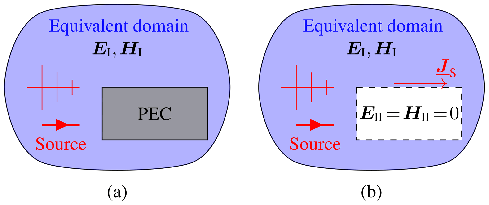
Figure 1Surface equivalence principle for scattering by a perfect electric conductor (PEC) (a) Original problem. (b) Equivalent problem.
As mathematical instrument to investigate surface currents, Characteristic Mode Analysis (CMA) (Harrington and Mautz, 1971; Cabedo-Fabres et al., 2007; Chen and Wang, 2015) is applied. A CMA yields orthogonal basis functions, called Characteristic Modes, in which surface currents can be expanded. Characteristic Modes only depend on geometric and material properties of the test setup and are thus different for HIRF and DCI because of distinct boundary conditions introduced by the DCI adapters (Rothenhäusler and Gronwald, 2017).
Based on Characteristic Mode data of HIRF and DCI setups, a basis transformation of the HIRF surface current from HIRF modes to DCI modes is performed, by which expansion coefficients for a DCI surface current expansion follow. Its approximation to the HIRF current is analyzed by means of a relative error measure for complex-valued vector quantities. Unlike in Ückerseifer et al. (2019), the basis transformation algorithm employs only vector-matrix operations and is thus easier to automate for a broad frequency range and arbitrary DUTs including spherical bodies. Apart from the discussed surface current transformations, practical issues concerning the influence of DCI adapter impedance as well as injection and termination adapter positions on the surface current approximation is discussed.
Section 2 starts with a mathematical overview over CMA and its specific modal quantities. They constitute the foundation for a basis transformation algorithm subsequently demonstrated yielding DCI surface currents as approximation to HIRF surface currents. In order to apply this algorithm, Sect. 3 introduces HIRF and DCI test setups for three different canonical DUTs, whose modal properties are determined by a CMA. Finally, Sect. 4 presents computed DCI currents for these DUTs and compares them to HIRF currents in a broad frequency spectrum for different physical configurations of the DCI setup.
The mathematical notation throughout this paper indicates complex quantities with an underscore. In contrast to scalar quantities, vectors and matrices are symbolized by bold variables.
2.1 Characteristic Mode Analysis
Characteristic Mode Analysis for perfect electric conductors (PEC) is commonly based on the Electric Field Integral Equation (EFIE) operator (impedance matrix) set up in the Method of Moments (Harrington, 1967). In a CMA, the generalized eigenvalue problem
at a frequency f with real eigenvalues and eigenvectors Jn(f)∈ℝ called Characteristic Modes, both quantities of order n∈ℕ, is solved. The eigenvalues are commonly expressed in a more convenient form with limited value range as the modal significance
with , which indicates, how intensively the nth Characteristic Mode can contribute to a surface current distribution.As an example, Fig. 2 shows amplitude-normalized Characteristic Modes of a straight wire acting as DUT in HIRF and DCI configuration. The boundary conditions for the HIRF modes manifest as vanishing currents at both wire ends, whereas for the DCI modes non-vanishing boundary currents occur because of DCI adapters attached to each wire end. Similar differences between HIRF and DCI modes occur for more complex bodies as well.
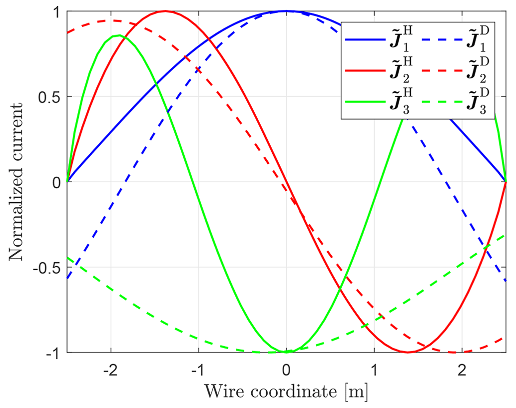
Figure 2Normalized Characteristic Modes of a straight wire (l=5 m) in HIRF and DCI configuration for n=1, 2, 3.
As the Jn are linearly independent, they form a basis in which the surface current on a DUT resulting from a HIRF test can be expanded. Assuming a test frequency fH, an expansion in M Characteristic Modes is set up according to
Here, denote Characteristic Modes of the HIRF setup and the expansion coefficients are called modal weighting coefficients. Both quantities are provided by numerical software tools.To investigate whether a DCI surface current can theoretically approximate a HIRF current distribution, the latter needs to be expandable in Characteristic Modes of the DCI setup, , and corresponding modal weighting coefficients like
where fD is the frequency, at which a CMA of the DCI setup is carried out. Appropriate for an adequate approximation of by can be obtained via a basis transformation algorithm described in Knabner and Barth (2018). It is implemented in MATLAB (, ) using CMA data generated by the integral equation solver of CST Microwave Studio (, ) for DUTs with NDUT mesh elements. Due to its enhanced mesh capabilities, all meshes are created in the numerical software FEKO (, ) with a standard level of discretization and imported to CST in NASTRAN format. The DCI mesh with mesh elements serves as reference, from which the HIRF mesh with NHIRF=NDUT elements is obtained by omitting the adapter mesh elements NADAP. This ensures equal positions of all mesh elements for the HIRF and DCI setups and thus enables an element-wise surface current comparison of both test methods.
2.2 Basis transformation
2.2.1 One-dimensional DUT
A basis transformation matrix T with elements tnm for the transformation of one-dimensional current distributions is deduced by expanding each as linear combination of all like
The approximation sign is due to finite summation over M Characteristic Modes as well as the different boundary conditions for HIRF and DCI modes, see Fig. 2. In Eq. (5), the only include the NDUT mesh elements belonging to the DUT, since the basis transformation can only be applied to these current elements.
In order to transform Eq. (5) from an index representation to a matrix one, both sets of Characteristic Modes , evaluated at the ith mesh element, are collected as column vectors in two matrices yielding
At a given simulation frequency f, these matrices contain the most significant modes, i.e. , which are found by deactivating mode tracking (Ludick et al., 2014) in the CMA solver of CST. With Eq. (6), the equivalent matrix form of Eq. (5) reads as
The desired transformation matrix T is hence
and (VD)−1 is in general, i.e. for non-quadratic matrices VD (M≠N), evaluated as Moore-Penrose inverse (pseudoinverse), see Campbell and Meyer (2009).
With the help of T, the vectorized DCI weighting coefficients in Eq. (4) follow from the HIRF weighting coefficients via a coordinate transformation. It is deduced, in a first step, by inserting Eq. (5) in Eq. (3) with the result
and a subsequent comparison of coefficients with Eq. (4) as
or in matrix-vector notation
Having determined , expansion (4) can be set up and compared to the current .
2.2.2 Two- or three-dimensional DUT
In two or three dimensions the HIRF weighting coefficients are transformed into separate DCI weighting coefficients for each cartesian current component. For this purpose, the matrices (6) are split into and containing only one single cartesian component of . This yields transformation matrices
and weighting coefficients
by which the cartesian current components are expanded as
They can be combined to , which equals the seeked approximation (4) of the surface current .
Figure 3 summarizes the overall basis transformation algorithm implemented in MATLAB based on Characteristic Mode data of HIRF and DCI setups provided by CST. Having determined the DCI expansion , its goodness of approximation to the reference current can be analyzed in a last step.
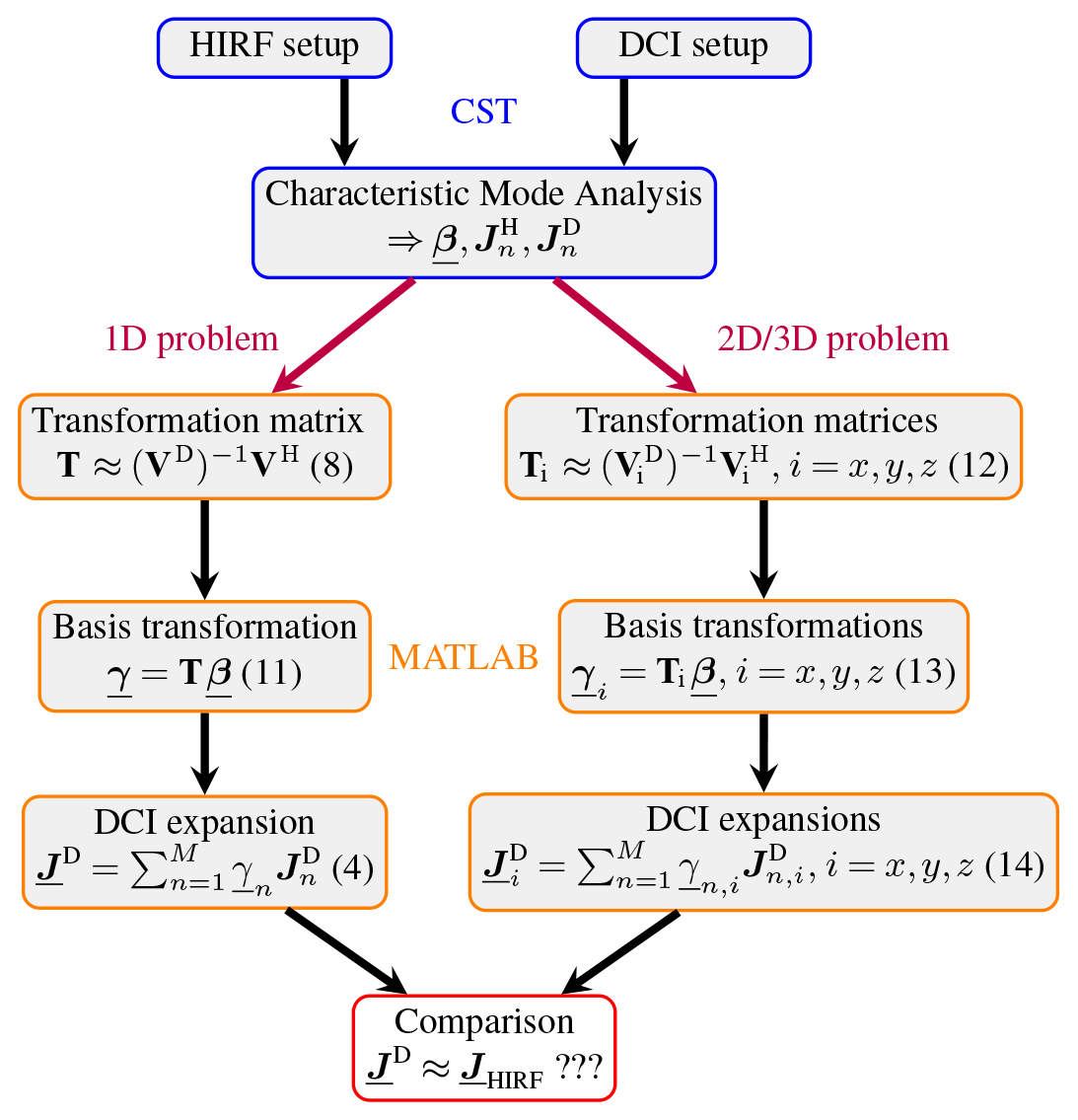
Figure 3Determination of suitable DCI surface currents from Characteristic Mode data of HIRF and DCI setups.
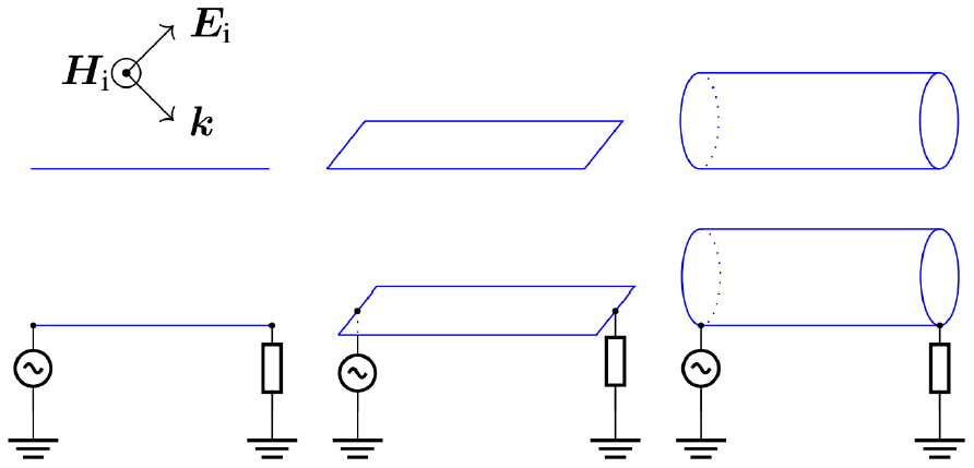
The outlined basis transformation is applied to three canonical DUTs (straight wire, rectangular plate, circular cylinder) modelled as PEC in HIRF and DCI configuration for fH=fD, see Fig. 4. Each HIRF setup consists of an infinite PEC ground plane placed 1 m beneath the DUT. It is exposed to a plane wave with an electric field amplitude of |Ei|=1 V m−1 and a polarization angle of 45∘ at two exemplary frequencies MHz and MHz for which the DUT appears electrically large (resonance region), such that a sufficient number of Characteristic Modes is excited (Blevins, 2006). The corresponding DCI setup vertically connects the DUT to this ground plane by one injection and one termination adapter, either having a characteristic impedance of Ω.
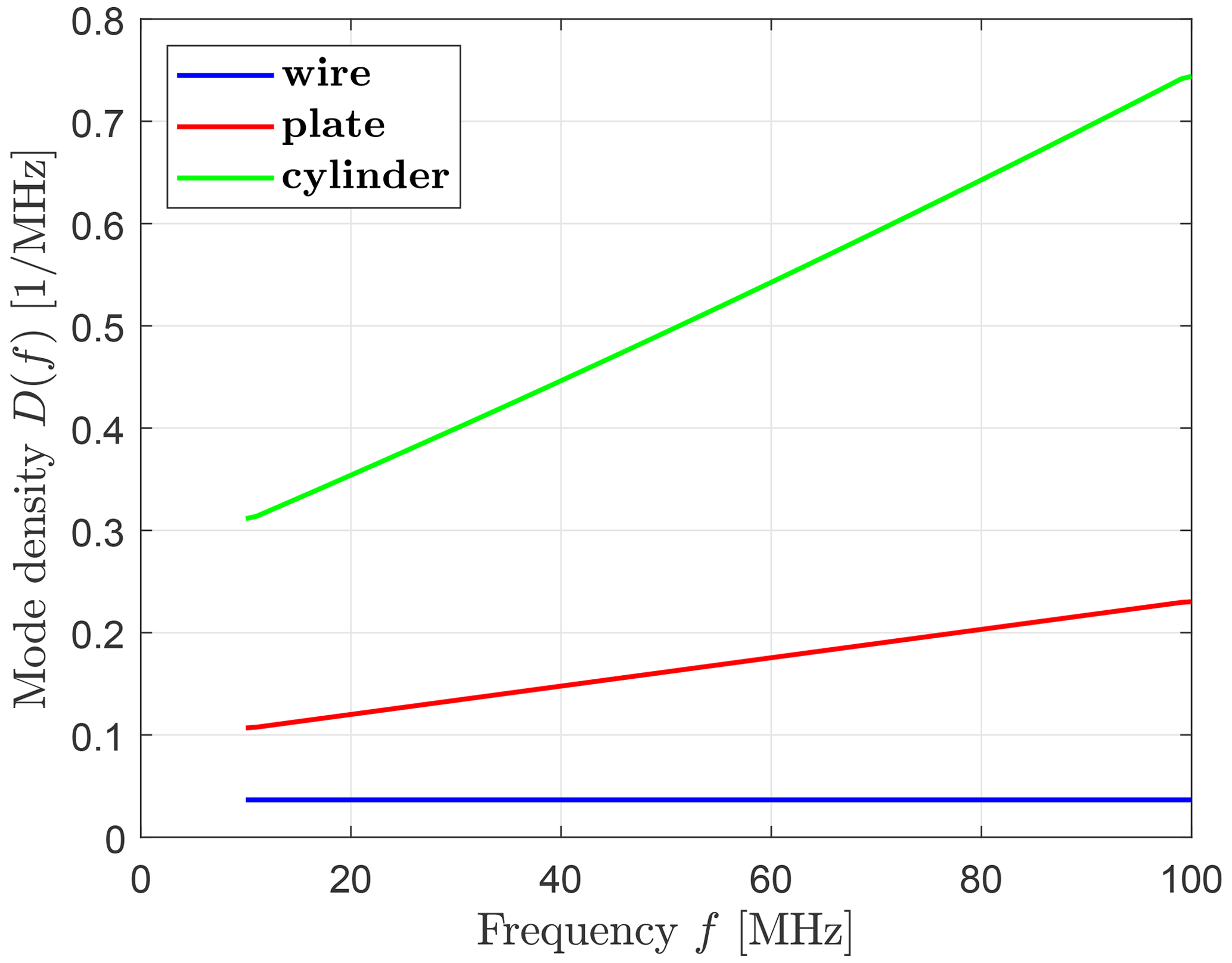
The number of Characteristic Modes N(f) present on all three test objects in free space is illustrated in Fig. 5 for modes fulfilling sn≥0.1. Due to low-frequency instabilities inherent to RWG-based (Rao–Wilton–Glisson) EFIE formulations of CMA (Qian and Chew, 2008), (Dai et al., 2017), especially for those containing line sources like DCI excitations (Hofmann et al., 2022), the lower frequency is chosen sufficiently high in order to obtain a substantial number of modes. Based on the polynomially fitted number of modes in Fig. 5, the mode density in Fig. 6 is calculated. It shows a constant mode density for the wire, a linearly rising one for the plate and a parabolic one in accordance with results for ordinary and generalized eigenvalue problems in Blevins (2006), Courant and Hilbert (1924).
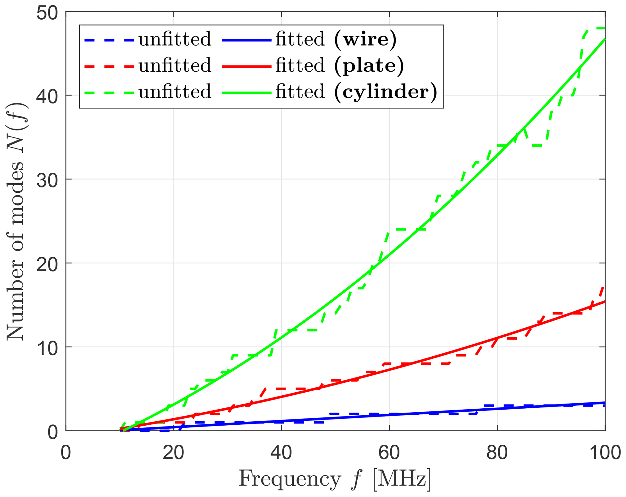
Figure 5Unfitted and fitted number of Characteristic Modes N(f) for wire, plate and cylinder.
4.1 Current distributions for HIRF and DCI
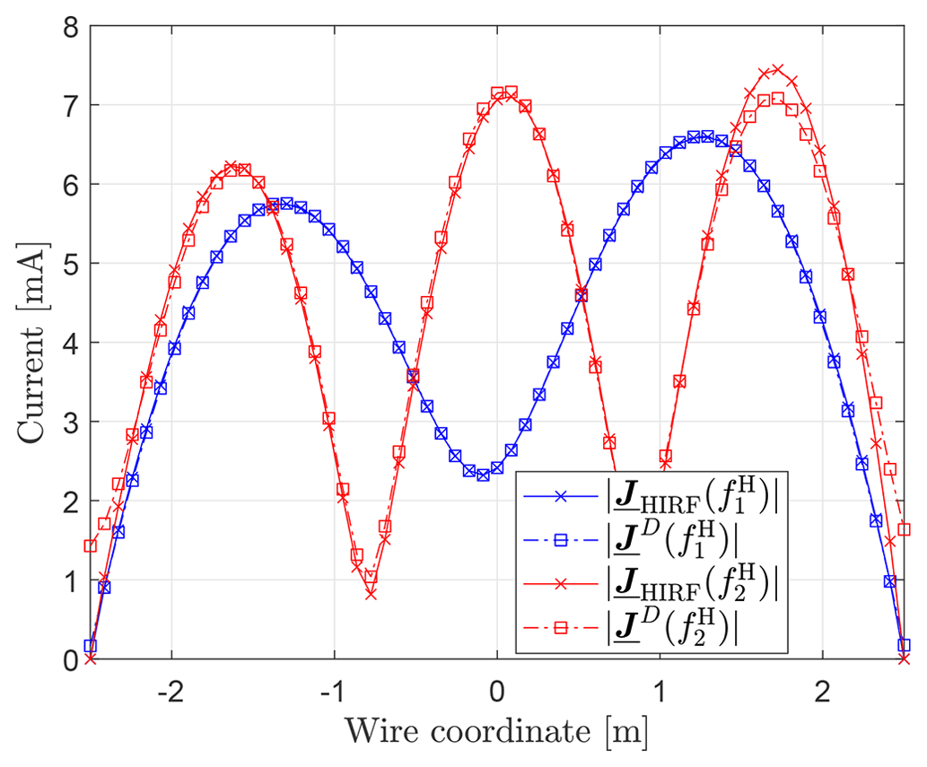
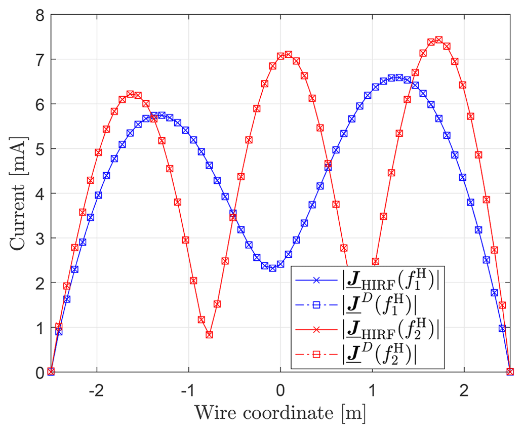
Figure 7 illustrates the currents on a straight wire (length l=5 m, radius r=1 mm) with NDUT=58 mesh segments for M=5. Both curves show a good agreement at , but at slight amplitude deviations and, more importantly, non-vanishing boundary currents due to current injection by the DCI adapters occur. Both effects can be mitigated by increasing M, as can be seen in Fig. 8.
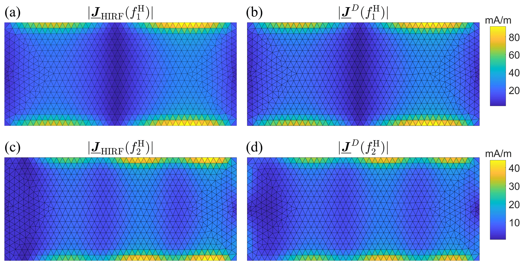
The surface currents on a rectangular plate (5 m × 2 m) with NDUT=1464 mesh triangles are plotted in Fig. 9 (top view). Even though the number of modes is increased to M=10, certain amplitude deviations at remain visible. This is explainable with an increased mode density for two-dimensional DUTs, as emphasized in Fig. 6.
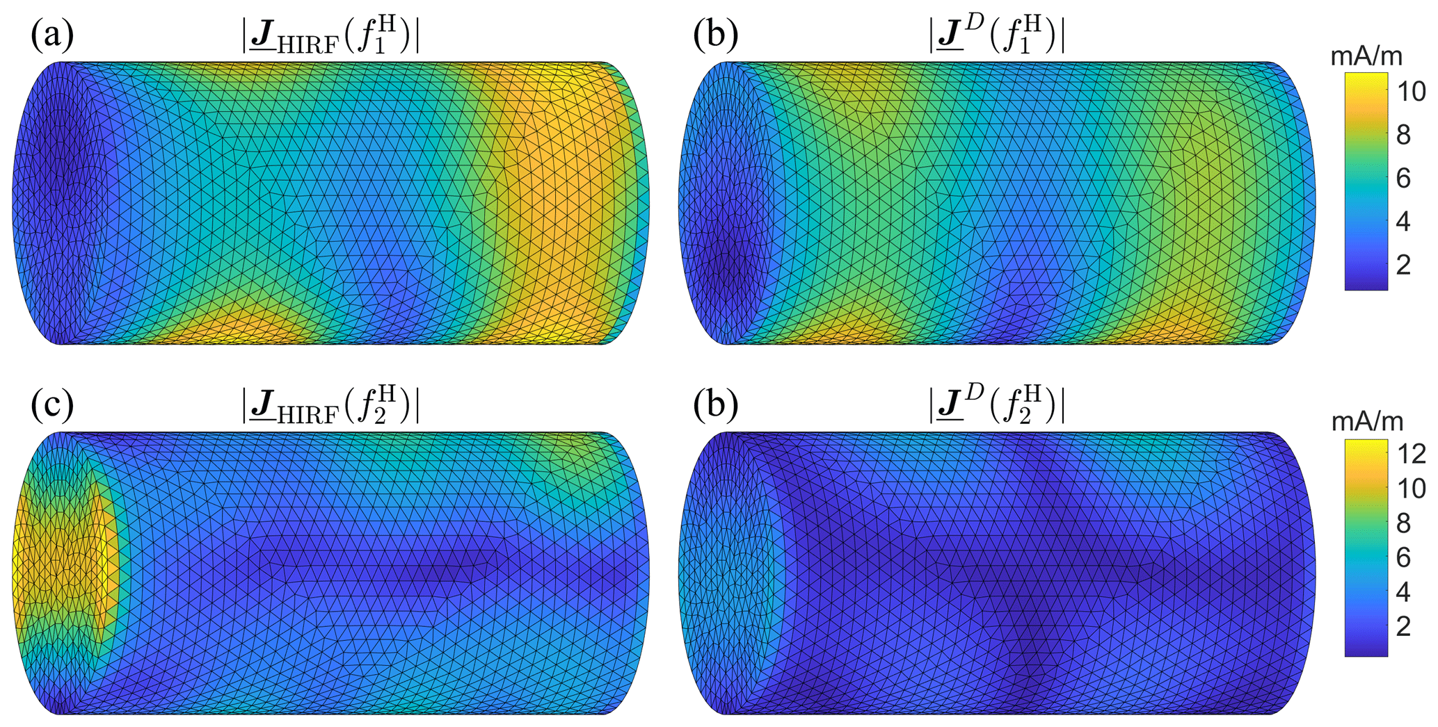
Finally, the surface currents on a cylinder (l = 5 m, r=1 m) meshed with NDUT = 5692 triangles are shown in Fig. 10 for M=10. In this scenario, the approximation of the HIRF current at both frequencies is insufficient owing to the even higher mode density of volumetric bodies, again conveyed by Fig. 6. Since it is known that inner resonances of volumetric bodies deteriorate the accuracy of EFIE-based CMA formulations because of an ill-conditioned impedance matrix (Dai et al., 2015), the more stable Combined Field Integral Equation (CFIE) formulation of CMA is used for the cylinder (Mautz and Harrington, 1977).
4.2 Broadband comparison of HIRF and DCI
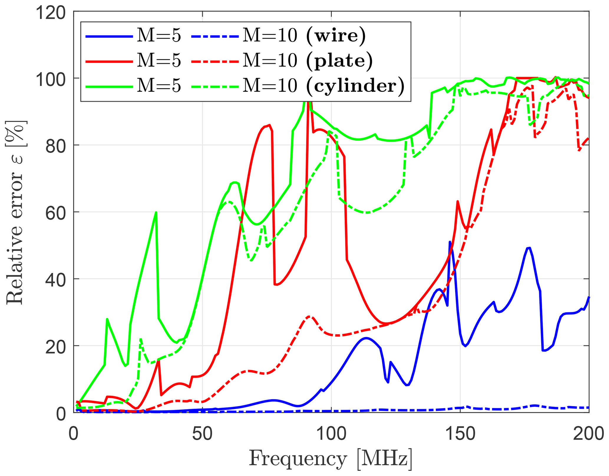
The approximation of the HIRF current by the DCI expansion can be quantified over a broad frequency range for all three DUTs. A measure for the relative error of two complex-valued vector quantities (Mittra, 2014) defined at a mesh element i is
whose result is shown in Fig. 11 from 1 to 200 MHz in steps of 1 MHz and different M for wire, plate and cylinder. In accordance with the previous results, it is visible that more modes are required at higher frequencies due to a higher mode density for geometric complex DUTs. In contrast, a relatively small error of approximately 20 % can be observed for the wire and plate up to frequencies of around 100 MHz. Steep ascents and descents in ε between neighbouring frequencies indicate changes in the sorting of Characteristic Modes deriving from deactivated mode tracking in CST (Ludick et al., 2014).
In Eq. (15), all DUT mesh elements are evaluated, although for EMC testing an approximation of interference maxima is most important. A criterion to include only mesh elements of relevant current amplitude is their energy contribution to the total current distribution. Since the PEC boundary condition
on a boundary described by its unit normal vector n enforces identical amplitudes of surface current and magnetic field , each current element can be assigned a magnetic energy (Pozar, 2011)
within a local mesh element volume Vi close to the DUT surface. In Eq. (17), the complex conjugate of is indicated by an asterisk. Calculating all Wi and sorting them in descending order (), these elements of highest energy can be summed up and related to the total energy
present in the accumulated volume according to
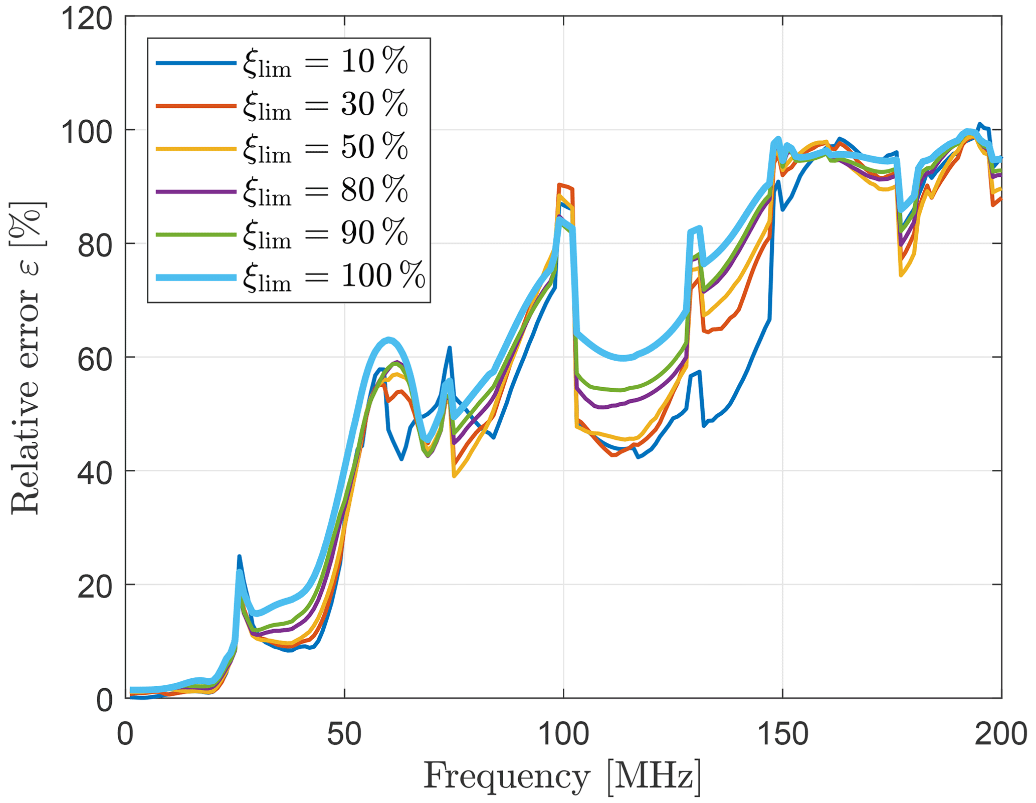
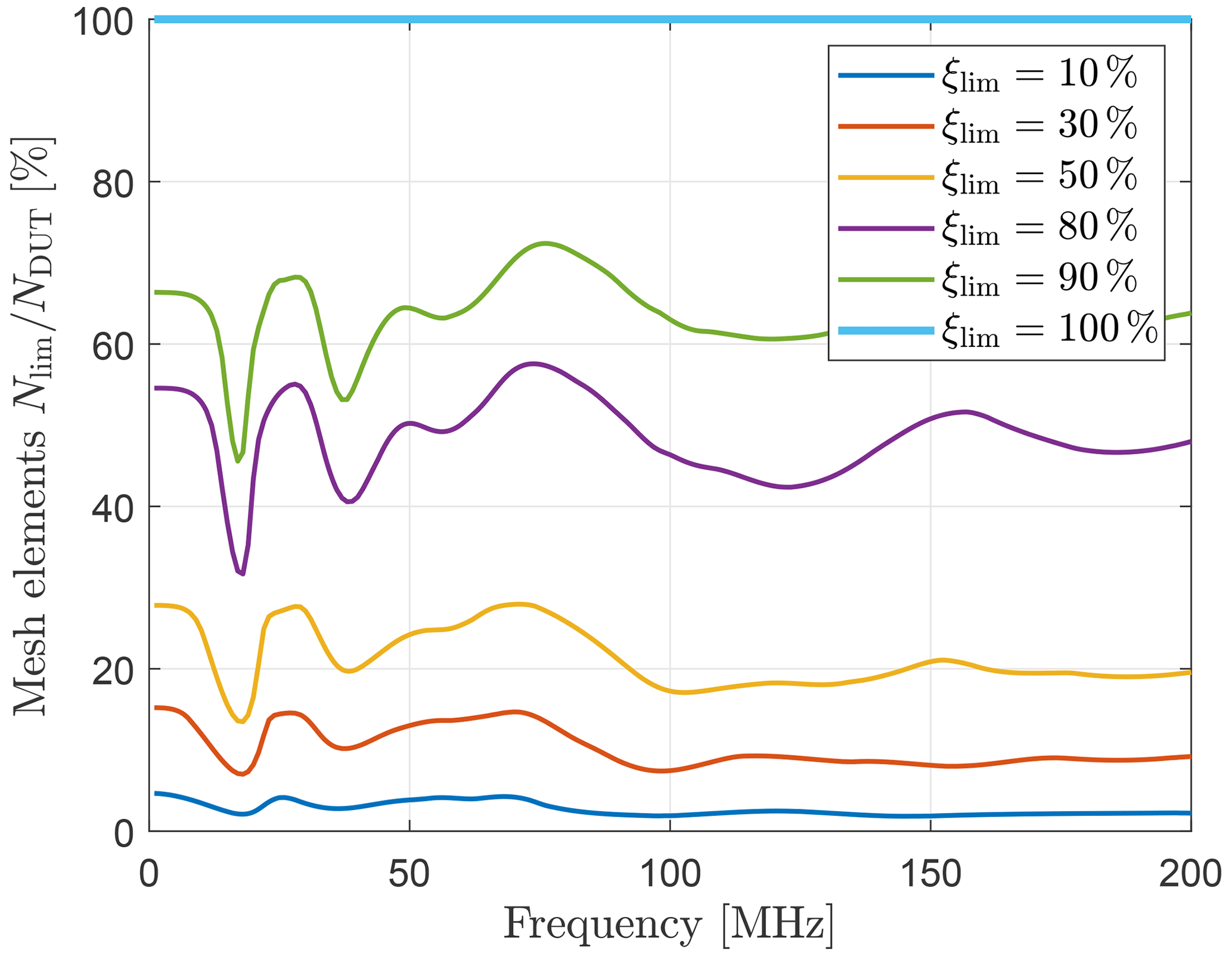
until at a certain number of considered elements Nlim a predefined percentual limit ξlim is exceeded. For several values ξlim, Fig. 12 shows the relative error ε with NDUT in Eq. (15) replaced by Nlim regarding the cylinder. Apparently, mesh elements with high energy dominate the overall surface current approximation, as adding low-energy elements does not significantly affect the error at most frequencies. Figure 13, in addition, reveals the required number of elements Nlim referenced to all NDUT elements to reach the limits ξlim. It is remarkable, comparing to Fig. 12, that a very limited number of mesh elements is responsible for the surface current approximation.
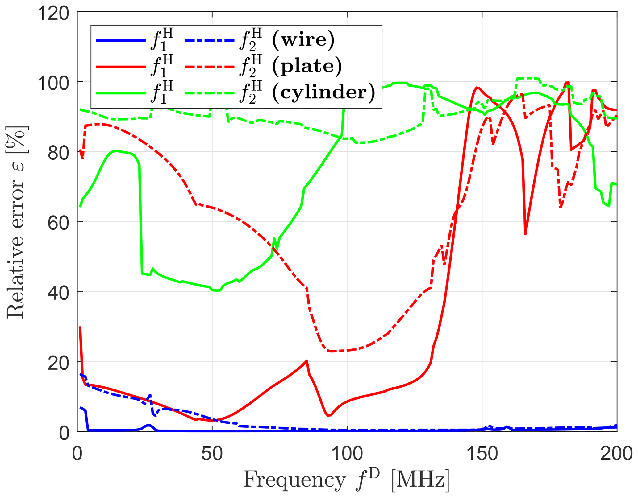
Hitherto, the frequencies fH and fD were identical. Since the DCI adapters change the electrical properties of the DUT, an investigation, whether CMA frequencies fD ≠ fH lead to a better approximation of the HIRF current at and , appears meaningful. Figure 14 conveys that a reasonable approximation can likewise be achieved for frequencies fD different from . In particular, optimal approximations for e.g. the plate are encountered at fD = and for the cylinder at frequencies fD=52 MHz ≠ and fD = 105 MHz ≠ .
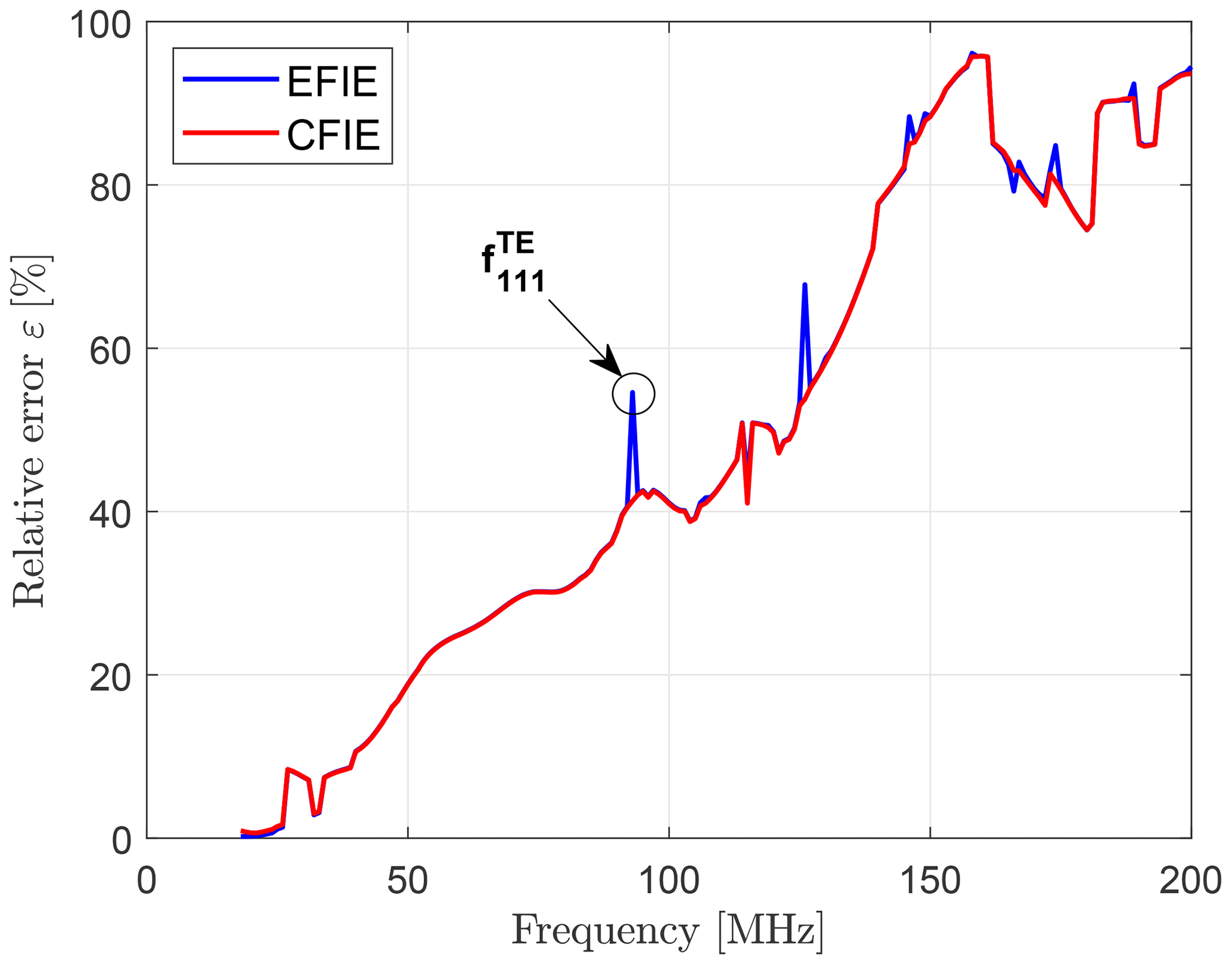
The impact of different CMA formulations on the surface current error for the cylinder is depicted in Fig. 15. In contrast to the CFIE solution, the EFIE formulation suffers from discontinuities at inner resonances of the cylinder. For the given case , the dominant TE111 mode with a resonant frequency defined by the pth zero of the ordinary Bessel function's derivative according to
of MHz (Hill, 2009) can be identified as first peak in Fig. 15. The basis transformation algorithm obviously can not overcome the drawbacks of inner resonances related to the EFIE formulation.
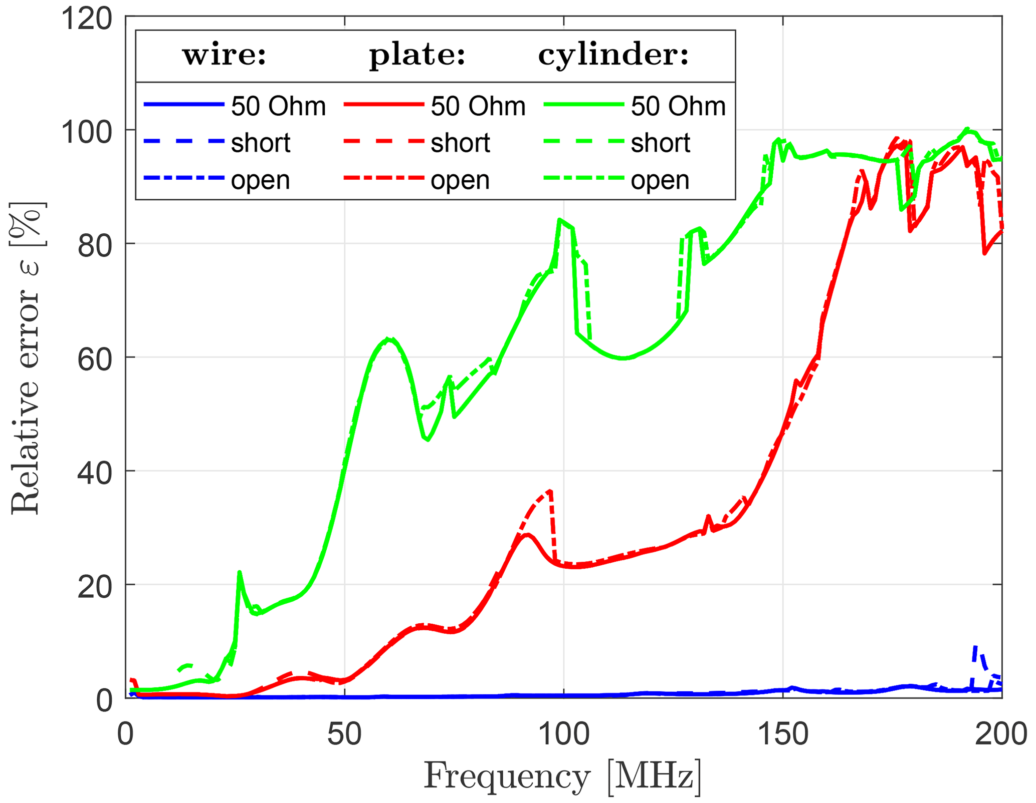
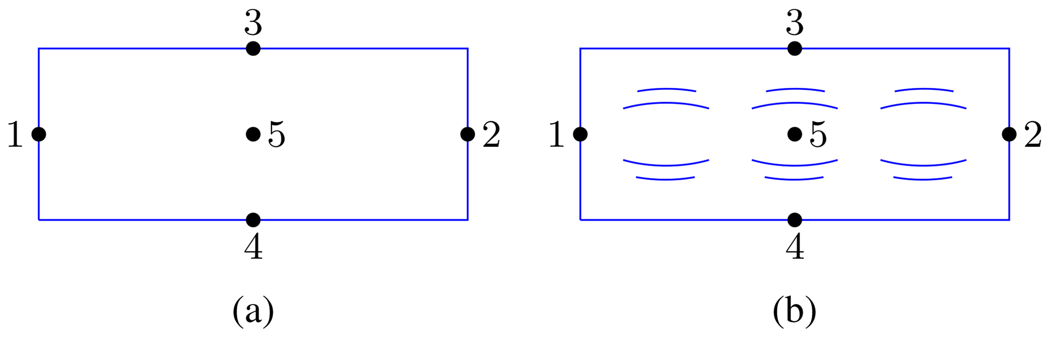
As additional degree of freedom, the termination adapter impedance Zterm in Fig. 4 can be altered from a matched condition (Zterm=50 Ω) to the extrema of a short circuit (Zterm=1µΩ) and an open circuit (Zterm=1 MΩ), see Fig. 16. In general, the curves show a good correspondence despite the significant impedance range. Consequently, the impedance can be chosen to fulfil practical criteria like impedance matching to achieve sufficient test levels.
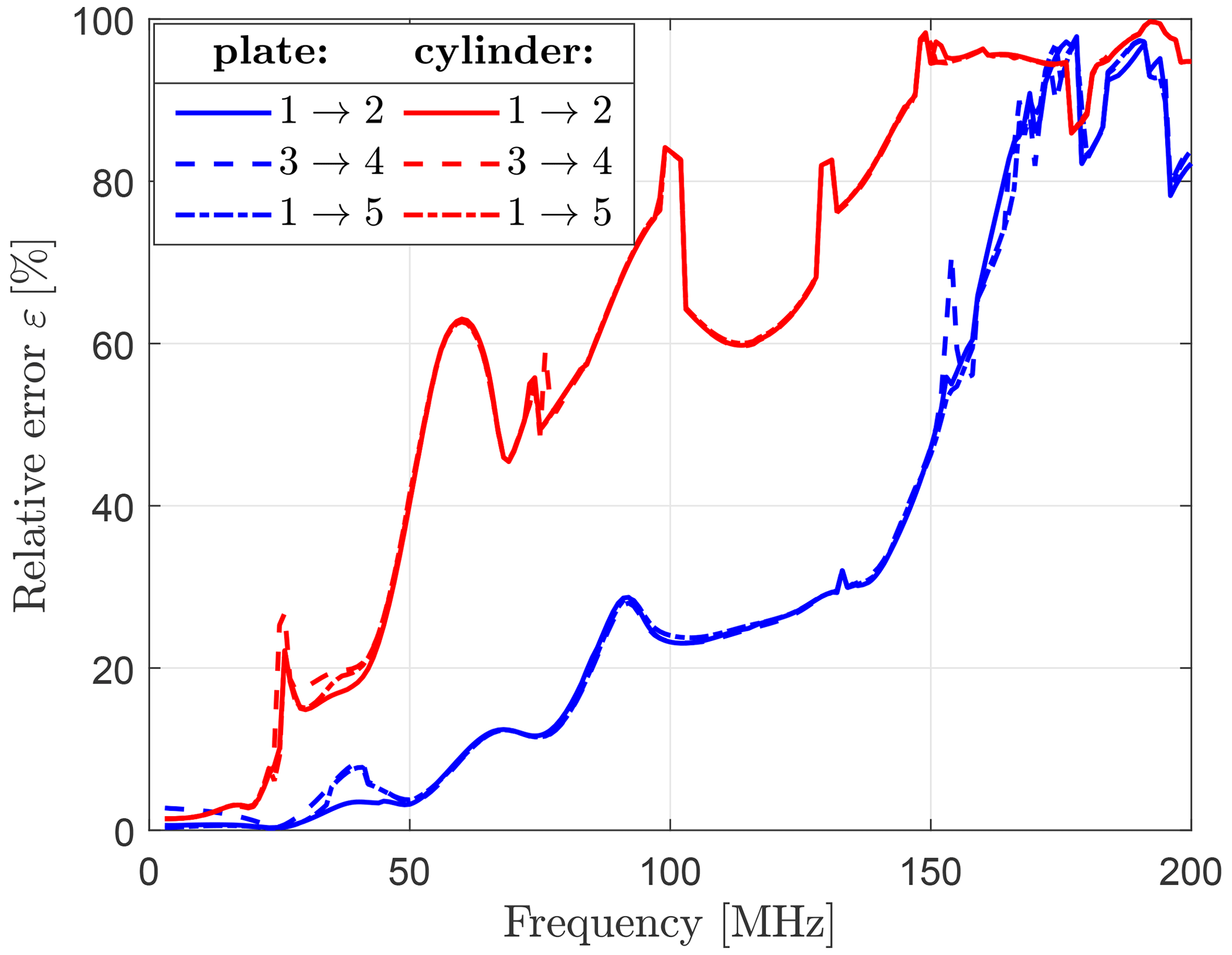
A further study involves the placement of injection and termination adapters (), which are indicated by numbered dots in Fig. 17. In addition to the excitation scenario 1→2 of Fig. 4, the cases 3→4 and 1→5 are analyzed with the outcome in Fig. 18. All adapter configurations result in similar errors, such that for practical considerations those adapter positions enabling an independent excitation of Characteristic Modes should be selected (Peitzmeier and Manteuffel, 2018, 2019).
The presented results show that, in theory, radiated immunity tests can be approximated well by conducted immunity tests at relatively low test frequencies for simple DUTs. As a means of analysis, CMA and the outlined basis transformation algorithm provide a systematic approach to determine suitable DCI excitations for a large variety of DCI configurations. Especially at low frequencies with a small mode density a good agreement between the HIRF currents and their approximation in DCI modes is achieved. The approximation is primarily determined by a restricted amount of relevant mesh elements. When the mode density increases simultaneously to the frequency, a sound approximation is difficult to realize for complex DUTs and a large number of modes is required. Moreover, the algorithm is computationally expensive, since for each physical change of the DCI setup, a new CMA in the entire frequency range is necessary.
The data presented in this article are available from the authors upon request.
The numerical simulations and data processing including all graphical representations were contributed by JÜ. Editorial hints as well as mathematical and physical suggestions were given by FG.
At least one of the (co-)authors is a member of the editorial board of Advances in Radio Science. The peer-review process was guided by an independent editor, and the authors also have no other competing interests to declare.
Publisher's note: Copernicus Publications remains neutral with regard to jurisdictional claims made in the text, published maps, institutional affiliations, or any other geographical representation in this paper. While Copernicus Publications makes every effort to include appropriate place names, the final responsibility lies with the authors.
This article is part of the special issue “Kleinheubacher Berichte 2022”. It is a result of the Kleinheubacher Tagung 2022, Miltenberg, Germany, 27–29 September 2022.
The authors would like to thank the referees for their helpful comments to improve this paper as well as Dirk Manteuffel for fruitful discussions regarding low-frequency instabilities in RWG-based CMA formulations.
This paper was edited by Lars Ole Fichte and reviewed by Blaise Elysée Guy Ravelo and two anonymous referees.
Altair Engineering: Feldberechnung für Körper mit beliebiger Oberfläche (FEKO), Version 2022.0.1. a
Blevins, R. D.: Modal density of rectangular volumes, areas, and lines, J. Acoust. Soc. Am., 119, 788–791, 2006. a, b
Cabedo-Fabres, M., Antonino-Daviu, E., Valero-Nogueira, A., and Bataller, M. F.: The Theory of Characteristic Modes Revisited: A Contribution to the Design of Antennas for Modern Applications, IEEE Antenn. Propag. M., 49, 52–68, https://doi.org/10.1109/MAP.2007.4395295, 2007. a
Campbell, S. and Meyer, C.: Generalized Inverses of Linear Transformations, Society for Industrial and Applied Mathematics, 2009. a
Carter, N. and Willis, P.: EMC testing of high-integrity digital systems in aircraft, in: IEE Colloquium on EMC in High Integrity Digital Systems, 17 May 1991, London, UK, 4/1–4/9, 1991. a
Chen, Y. and Wang, C.: Characteristic Modes: Theory and Applications in Antenna Engineering, Wiley, https://doi.org/10.1002/9781119038900, 2015. a
Courant, R. and Hilbert, D.: Methoden der mathematischen Physik, 1, Heidelberg, 1924. a
Dai, Q. I., Liu, Q. S., Gan, H. U. I., and Chew, W. C.: Combined Field Integral Equation-Based Theory of Characteristic Mode, IEEE T. Antenn. Propag., 63, 3973–3981, https://doi.org/10.1109/TAP.2015.2452938, 2015. a
Dai, Q. I., Gan, H. U. I., Liu, Q. S., and Chew, W. C.: Characteristic Mode and Reduced Order Modeling at Low Frequencies, IEEE T. Compon. Pack. T., 7, 669–677, https://doi.org/10.1109/TCPMT.2017.2659699, 2017. a
Dassault Systèmes: CST Studio Suite 2021, Version 2021.05. a
EUROCAE: ED-107A – Guide to Certification of aircraft in a High-Intensity Radiated Field (HIRF) Environment, 2010. a
Harrington, R.: Time-harmonic Electromagnetic Fields, McGraw-Hill, 1961. a
Harrington, R.: Matrix methods for field problems, Proceedings of the IEEE, 55, 136–149, https://doi.org/10.1109/PROC.1967.5433, 1967. a
Harrington, R. and Mautz, J.: Theory of characteristic modes for conducting bodies, IEEE T. Antenna. Propag., 19, 622–628, https://doi.org/10.1109/TAP.1971.1139999, 1971. a
Hill, D.: Electromagnetic Fields in Cavities: Deterministic and Statistical Theories, IEEE Press Series on Electromagnetic Wave Theory, Wiley, 2009. a
Hofmann, B., Eibert, T. F., Andriulli, F. P., and Adrian, S. B.: Low-Frequency-Stabilized Electric Field Integral Equation on Topologically Non-Trivial Geometries for Arbitrary Excitations, in: 2022 IEEE International Symposium on Antennas and Propagation and USNC-URSI Radio Science Meeting (AP-S/URSI), 10–15 July 2022, Denver, CO, USA, 1938–1939, https://doi.org/10.1109/AP-S/USNC-URSI47032.2022.9886833, 2022. a
Jin, J. M.: Theory and Computation of Electromagnetic Fields, Wiley, https://doi.org/10.1002/9780470874257, 2010. a
Knabner, P. and Barth, W.: Lineare Algebra: Grundlagen und Anwendungen, Springer Berlin Heidelberg, https://doi.org/10.1007/978-3-662-55600-9, 2018. a
Leat, C. J.: The Safety of Aircraft Exposed to Electromagnetic Fields: HIRF Testing of Aircraft Using Direct Current Injection, Australian Government Department of Defence, 2007. a
Ludick, D., Jakobus, U., and Vogel, M.: A tracking algorithm for the eigenvectors calculated with characteristic mode analysis, in: The 8th European Conference on Antennas and Propagation (EuCAP 2014), 6–11 April 2014, The Hague, the Netherlands, 569–572, https://doi.org/10.1109/EuCAP.2014.6901820, 2014. a, b
MathWorks: MATLAB, Version R2021b. a
Mautz, J. R. and Harrington, R. F.: H-field, E-field, and combined field solutions for bodies of revolution, Interim Report 1, Syracuse Univ., NY. Dept. of Electrical and Computer Engineering, 1977. a
Mittra, R.: Computational Electromagnetics: Recent Advances and Engineering Applications, Springer New York, https://doi.org/10.1007/978-1-4614-4382-7, 2014. a
Peitzmeier, N. and Manteuffel, D.: Selective excitation of characteristic modes on an electrically large antenna for MIMO applications, in: 12th European Conference on Antennas and Propagation (EuCAP 2018), 9–13 April 2018, London, UK, 1–5, https://doi.org/10.1049/cp.2018.0779, 2018. a
Peitzmeier, N. and Manteuffel, D.: Upper Bounds and Design Guidelines for Realizing Uncorrelated Ports on Multimode Antennas Based on Symmetry Analysis of Characteristic Modes, IEEE T. Antenn. Propag., 67, 3902–3914, https://doi.org/10.1109/TAP.2019.2905718, 2019. a
Pérez, F. C., Gutierrez Gutierrez, G., Tavares, H., Khamlichi, A., Alberquilla, J. M., Molero Castejón, R., Matos, N., and Linares, A. R.: Lightning Low Level vs High Level Direct Current Injection Tests on a Full Scale Aircraft Cockpit, in: 2019 International Symposium on Electromagnetic Compatibility (EMC EUROPE), 2–6 September 2019, Barcelona, Spain, 644–649, https://doi.org/10.1109/EMCEurope.2019.8871458, 2019. a
Pozar, D.: Microwave Engineering, 4th edn., Wiley, 2011. a
Qian, Z.-G. and Chew, W. C.: A quantitative study on the low frequency breakdown of EFIE, Microw. Opt. Techn. Lett., 50, 1159–1162, https://doi.org/10.1002/mop.23324, 2008. a
Rothenhäusler, M. and Gronwald, F.: Characteristic mode analysis of HIRF- and DCI-excitations of an aircraft structure, in: 2017 International Symposium on Electromagnetic Compatibility (EMC EUROPE), 4–7 September 2017, Angers, France, 1–6, https://doi.org/10.1109/EMCEurope.2017.8094764, 2017. a
Rothenhäusler, M., Schoisl, A., and Schwarz, M.: Numerical Simulation of a Direct Current Mode Stirred Reverberation Chamber, in: 2019 International Symposium on Electromagnetic Compatibility (EMC EUROPE), 2–6 September 2019, Barcelona, Spain, 247–252, https://doi.org/10.1109/EMCEurope.2019.8872037, 2019. a
Rothenhäusler, M., Ruhfass, A., Schneider, S., Schoisl, A., and Schwarz, M.: Direct Current Mode Stirred – Susceptibility Testing Results of a small EUT and Comparison to RC and SAC Results, in: 2023 International Symposium on Electromagnetic Compatibility (EMC EUROPE), 4–8 September 2023, Krakow, Poland, 1–6, https://doi.org/10.1109/EMCEurope57790.2023.10274247, 2023. a
Ückerseifer, J., Aidam, M., Rothenhäusler, M., and Gronwald, F.: A Numerical Analysis of HIRF- and DCI-Equivalence by Characteristic Mode Theory, in: 2019 International Symposium on Electromagnetic Compatibility (EMC EUROPE), 2–6 September 2019, Barcelona, Spain, 315–320, https://doi.org/10.1109/EMCEurope.2019.8871548, 2019. a, b
Ückerseifer, J., Kong, T., and Gronwald, F.: A statistical approach towards the equivalence of HIRF and DCI test setups, in: 2021 XXXIVth General Assembly and Scientific Symposium of the International Union of Radio Science (URSI GASS), 28 August–4 September 2021, Rome, Italy, 1–4, https://doi.org/10.23919/URSIGASS51995.2021.9560492, 2021. a
Ückerseifer, J., Xu, S., and Gronwald, F.: Statistical Inference of Electric Fields in Lossy Reverberating Environments Subject to High Intensity Radiated Field and Direct Current Injection, in: 2023 International Symposium on Electromagnetic Compatibility (EMC Europe) Krakow, Poland, 1–6, https://doi.org/10.1109/EMCEurope57790.2023.10274327, 2023. a
Wang, Q., Zhou, X., and Gu, Y.: The correlation and an equivalent method of direct current injection (DCI) and high-intensity radiated field (HIRF) on the wire, in: 2020 6th Global Electromagnetic Compatibility Conference (GEMCCON), 20–23 October 2020, Xi'an, China, 1–4, https://doi.org/10.1109/GEMCCON50979.2020.9456728, 2020. a