 | 01 Dec 2023
Generalized Efficiency and the Uncertainty of Millimeter Wave Power Standard
Windi Kurnia Perangin-Angin
Karsten Kuhlmann
Jürgen Rühaak
In the last decade, waveguide thermoelectric power sensors have been established as an alternative to thermistor mounts for millimeter wave power standards, and due to the detection principle and the nature of waveguides, the generalized efficiency is used as calibration quantity instead of the effective efficiency. In this paper, the generalized efficiency and the measurement uncertainty of waveguide thermoelectric sensors are presented and applied to calibrate other types of power sensors in a measurement set-up for frequency up to 170 GHz. Results for commercially available waveguide power sensors are discussed for the interfaces R 900 and R 1.4k.
- Article
(2444 KB) - Full-text XML
- BibTeX
- EndNote


Telecommunication devices have grown rapidly in the last decade. Millimeter wave power is one of the fundamental measurement quantities in telecommunication devices. Millimeter wave power standards and systems are needed to ensure quality. Bolometric sensors are utilized by most of the National Metrology Institutes (NMIs) as transfer standard to establish measurement traceability of the millimeter wave power to the primary standard, namely microcalorimeter. The effective efficiency of bolometric set-ups, often a thermistor mount, is measured in the microcalorimeter measurement system (Brunetti et al., 2013). Subsequently, the calibrated thermistor mount is used as reference standard in a direct transfer system to calibrate power sensors, power meters, and other radio frequency (RF) instruments for calibration laboratories and industries (Fantom, 1990; Weidman, 1994).
Since at least two decades, waveguide thermistor mounts in the millimeter wave range are not commercially available anymore, and thermoelectric power sensors are used more and more as transfer standards to establish the measurement traceability for these high frequencies (Judaschke et al., 2015). Originally, the effective efficiency was used as measurement quantity for the thermistor mount in compliance with the ratio of direct current (DC) power substitution and RF power. Moreover, the effective efficiency has been calculated also for the thermoelectric sensor by modifying the microcalorimeter measurement, particularly for the coaxial type (Vollmer et al., 1994). Nevertheless, due to the thermoelectric principle and the nature of waveguides, the effective efficiency cannot easily be applied (Chung et al., 1989; Judaschke et al., 2015).
The generalized efficiency is a modified calibration quantity introduced in 2014 for power transfer standards (Judaschke et al., 2014). Recently, more RF power laboratories apply waveguide thermoelectric sensor as a standard to calibrate commercial power sensors in direct transfer systems, thus this measurement quantity becomes more important in RF power measurement systems and is the focus of this work.
This paper describes the determination and application of the generalized efficiency of waveguide thermoelectric power sensors in the direct transfer system for the frequency range up to 170 GHz (R 1.4k). The waveguide thermoelectric sensor as millimeter wave power standard has been determined with a microcalorimeter system first, and the generalized efficiency is subsequently utilized to calibrate commercial power sensors used by calibration laboratories or industries as millimeter wave power standard. The R 1.4k waveguide thermoelectric power sensors in combination with a waveguide taper is also used to calibrate an R 900 power sensors at certain frequencies above 110 GHz.
The generalized efficiency of thermoelectric sensors is mathematically not too different from effective efficiency of thermistor mounts. In previous works (Judaschke et al., 2014), the generalized efficiency has been discussed for microcalorimeter set-ups. To establish millimeter wave power calibration services, the generalized efficiency must be applied in the direct transfer system.
2.1 Theory
The effective efficiency ηeff is defined as the ratio of the DC substituted power PDC and the absorbed RF power PRFabs within the bolometer element (Fantom, 1990) as shown in Eq. (1).
It's based on one absorber, while for the generalized efficiency two absorbers are used (Judaschke et al., 2015). The generalized efficiency of waveguide thermoelectric power sensors is the ratio of the DC substituted power in the DC heater and the RF power in the RF absorber for the same output voltage of a sensor thermopile (Judaschke et al., 2014).
The determination of the effective efficiency of thermistor mounts is done by the power substitution principle, often implemented by suitable measurement bridge circuitry (Weidman, 1994; Celep and Stokes, 2021). The DC substituted power is calculated by using Eq. (2),
where V1 is the DC voltage across the thermistor mount without RF power, V2 is the DC voltage across the thermistor mount with applied RF power, and R is the operating resistance of the thermistor mount which is usually 100 or 200 Ω (Cui et al., 2016). The principle of DC substitution cannot be easily applied for waveguide thermoelectric sensors. Here, the RF power enters the waveguide interface, and it is dissipated into an absorber. However, the DC power is dissipated into a DC heater, and a thermopile is used to indicate the same power absorbed between the DC power and the RF power (Reichel, 2013).
The calibration factor K of a thermistor sensor is defined as the ratio of the DC substituted power to the incident RF power PRFin as shown in Eq. (3) (Fantom, 1990).
While the effective efficiency is independent of the reflection coefficient Γ, the calibration factor includes both: the effective efficiency and the reflection coefficient, see Eq. (4).
2.2 Derivation of Incident RF Power of Waveguide Thermoelectric Sensor
Equation (5) shows how the incident RF power is obtained from the calibration factor and the DC substituted power, and the dependency of the calibration factor on the generalized efficiency ηgen of the waveguide thermoelectric sensors can be seen in Eq. (6), where eTRF is the output voltage of the thermopile in the RF measurement and eTDC is the output voltage of the thermopile in the DC measurement. The ηgen is identical to the effective efficiency for thermistor mounts.
A commercial power sensor usually shows the indicated power directly on a power meter display, while the output quantity of waveguide thermoelectric sensors is DC voltage VDC, measured with a precision multimeter. The indicated power is:
where RDC is the resistance of the DC heater of the waveguide thermoelectric sensor. Combining Eqs. (5) to (7) results in Eq. (8), the incident power.
Note: the thermopile voltage eTRF is equal to the voltage eTDC.
2.3 Determination of Generalized Efficiency of Waveguide Thermoelectric Sensor
Equation (9) is used to calculate the calibration factor of the device under test (DUT) power sensor KD in the conventional direct transfer system:
where KS is the calibration factor of the transfer standard, PD is the indicated RF power of the DUT power sensor, and PS is the indicated RF power of the transfer standard. The quantities ΓD, ΓS, and ΓGE are the reflection coefficients of the DUT power sensor, the transfer standard, and the RF source, respectively. A directional coupler and a monitoring power sensor are used to compensate for the thermal drift of the RF source. PMS indicates the monitored power reading when the reference standard is connected, and PMD the DUT reading.
Using Eqs. (5), (8), and (9) it follows:
where ηgenD is the generalized efficiency of the waveguide thermoelectric DUT sensor, PDCD is the DC substituted power of the waveguide thermoelectric DUT sensor, and PDCS the DC substituted power of the transfer standard. The voltages VDCD and VDCS are readings of the waveguide thermoelectric DUT sensor and of the resistive heater of the transfer standard, and RDCD and RDCS indicate the DC resistances of the waveguide thermoelectric DUT sensor and the transfer standard. The generalized efficiency of the transfer standard ηgenS has been determined in a microcalorimeter measurement. In this case, the transfer standard is also a waveguide thermoelectric sensor. Finally, the generalized efficiency of the waveguide thermoelectric DUT sensor in the direct transfer system is shown in Eq. (12).
The calibration factor of other power sensor types can be calculated in a similar manner by using the generalized efficiency of the waveguide thermoelectric sensor. In the measurements discussed in the following, a calorimeter-style power meter PM5B and a thermistor mount were used as DUT sensors. The indicated power PD is given directly by both power meters. Thus, the calibration factor of the DUT sensor is:
The actual determination of the generalized efficiency of the millimeter wave power standard consists of two main steps: RF power and DC power measurements are performed for the same thermopile output voltage. Both results are required to determine the generalized efficiency.
3.1 Measurement Setup of RF Power
The direct transfer system measurement set-up is shown in Fig. 1. The DUT power sensor and the transfer standard utilize waveguide interfaces. For calibration of commercial power sensors, the DUT power sensor is usually directly connected to a power meter. The direct transfer system is based on alternate connection between the transfer standard (reference) and the DUT power sensor at the measuring port (reference plane) while the monitoring power sensor is continuously connected to the coupled port of a 10 dB directional coupler (Weidman, 1994).
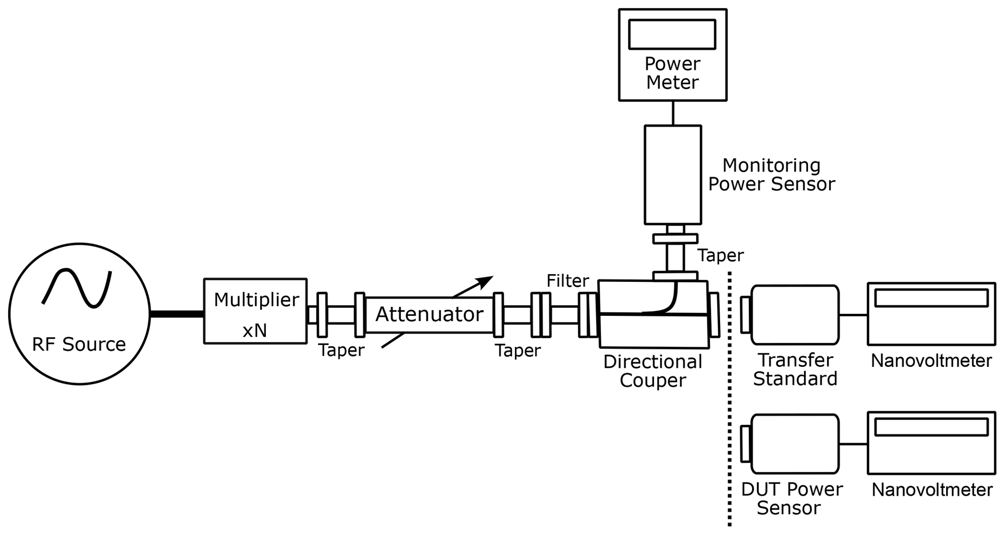
While measurement of RF power is conducted, the DC heater is unbiased and the DC circuitry is disconnected from the measurement system. The thermopile voltage of the transfer standard and the RF power of the monitoring power sensor PMS are measured first, and subsequently the thermopile voltage of the DUT power sensor and the RF power of the monitoring power sensor PMD are measured.
A combination of a signal generator and a multiplier with multiplication factor of six generates the RF signal. A rotary vane attenuator is utilized to set the power level of approximately 1 mW at the measuring port and 0.1 mW at the monitoring port. A filter is used to minimize harmonic signal content. Some tapers are required to match different waveguide apertures. The output voltage of the sensor thermopile of the RF load eTRF is measured by a nanovoltmeter.
3.2 Measurement Setup of DC Power
Figure 2 shows the DC power measurement setup, used to determine the DC substituted power. The RF devices are not connected to the measurement set-up when the DC power measurements are performed. A precision resistance temperature detector (RTD) simulator is utilized to adjust the output of a DC source. The adjustment can be conducted automatically by using a measurement program with Labview. A nanovoltmeter measures the output voltage of the sensor thermopile in the DC case eTDC. The DC source is adjusted until eTDC is (nearly) identical to eTRF.
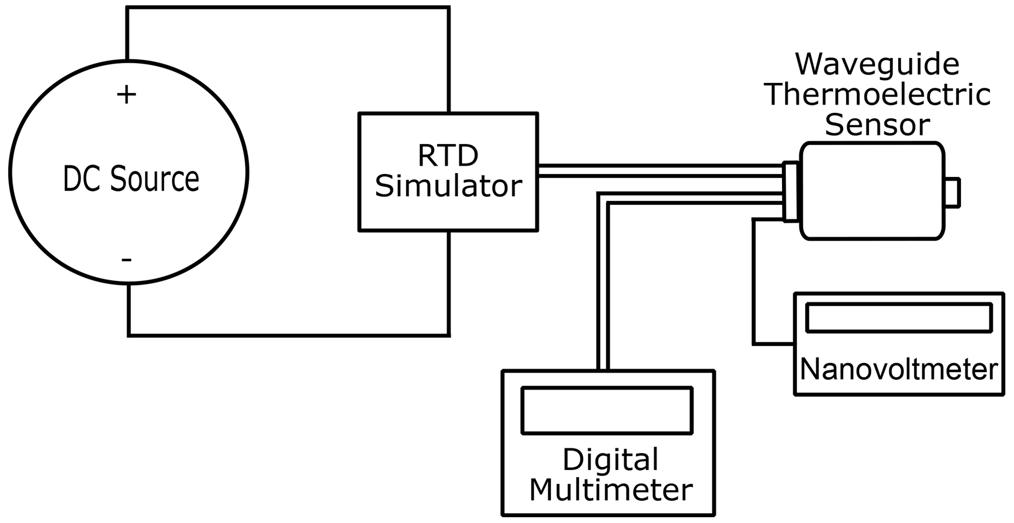
The voltages of the resistive heater of both the transfer standard and the DUT power sensor are measured by a digital multimeter. The DC substituted powers of the DUT power sensor and the transfer standard are calculated using Eqs. (10) and (11), respectively. The DC substituted powers are proportional to the RF powers in the previous measurements (Fantom, 1990).
Measurement result of the generalized efficiency of the waveguide thermoelectric DUT sensors NTS170TWG manufactured by Rohde and Schwarz in the direct transfer system is shown in Fig. 3. The measurement repeatability, five measurements were averages and analyzed, is better than 0.0045.

Figure 3Generalized efficiency with measurement repeatability (standard deviation) of the NTS170TWG waveguide thermoelectric DUT sensor in the direct transfer system.
For verification, the generalized efficiency of the millimeter wave power sensor in the direct transfer system is compared with a microcalorimeter result, shown in Fig. 4. An agreement of better than 0.013 is observed across the entire measurement range.

Figure 4Comparison of the generalized efficiency of the waveguide thermoelectric DUT sensor between two measurement methods.
The generalized efficiency of the waveguide thermoelectric sensor has been applied to calibrate the other types of power sensor, i.e. PM5B power meter and 45776H thermistor mount. Figure 5 shows the measurement of the calibration factor of the PM5B power meter with a repeatability better than 0.0055. The calibration factor has been calculated using Eq. (13). In the conventional direct transfer system using the thermistor mount as transfer standard, the calibration factor of the DUT sensor KD is calculated by applying the calibration factor of the transfer standard KS, as shown in Eq. (9). On the other hand, the calibration factor of the PM5B power meter is directly calculated by using the generalized efficiency of the waveguide thermoelectric transfer standard ηgenS.

Figure 5The calibration factor of the power meter PM5B with repeatability (standard deviation) in the direct transfer system.
Usually, a DUT power sensor is calibrated by a reference power sensor for the same frequency band (same waveguide apertures). E.g., an R 900 DUT power sensor is measured with an R 900 transfer standard. However, extending the frequency range is possible if a suitable adapter (taper) is used. Here, an R 1.4k thermoelectric sensor is applied as standard to determine the calibration factor of an R 900 thermistor mount above the usual band limits. The R 900 power sensor has a recommended frequency range from 75 to 110 GHz, and the cut-off frequency for the first higher mode is approximately 118 GHz (EverythingRF, 2022). R 1.4k sensors usually work within the frequency range of 110 to 170 GHz. Figure 6 shows the measurement of the calibration factor with its repeatability of the R 900 thermistor mount 45776H by using the R 1.4k thermoelectric standard in the direct transfer system. The measurement repeatability is better than 0.0061.
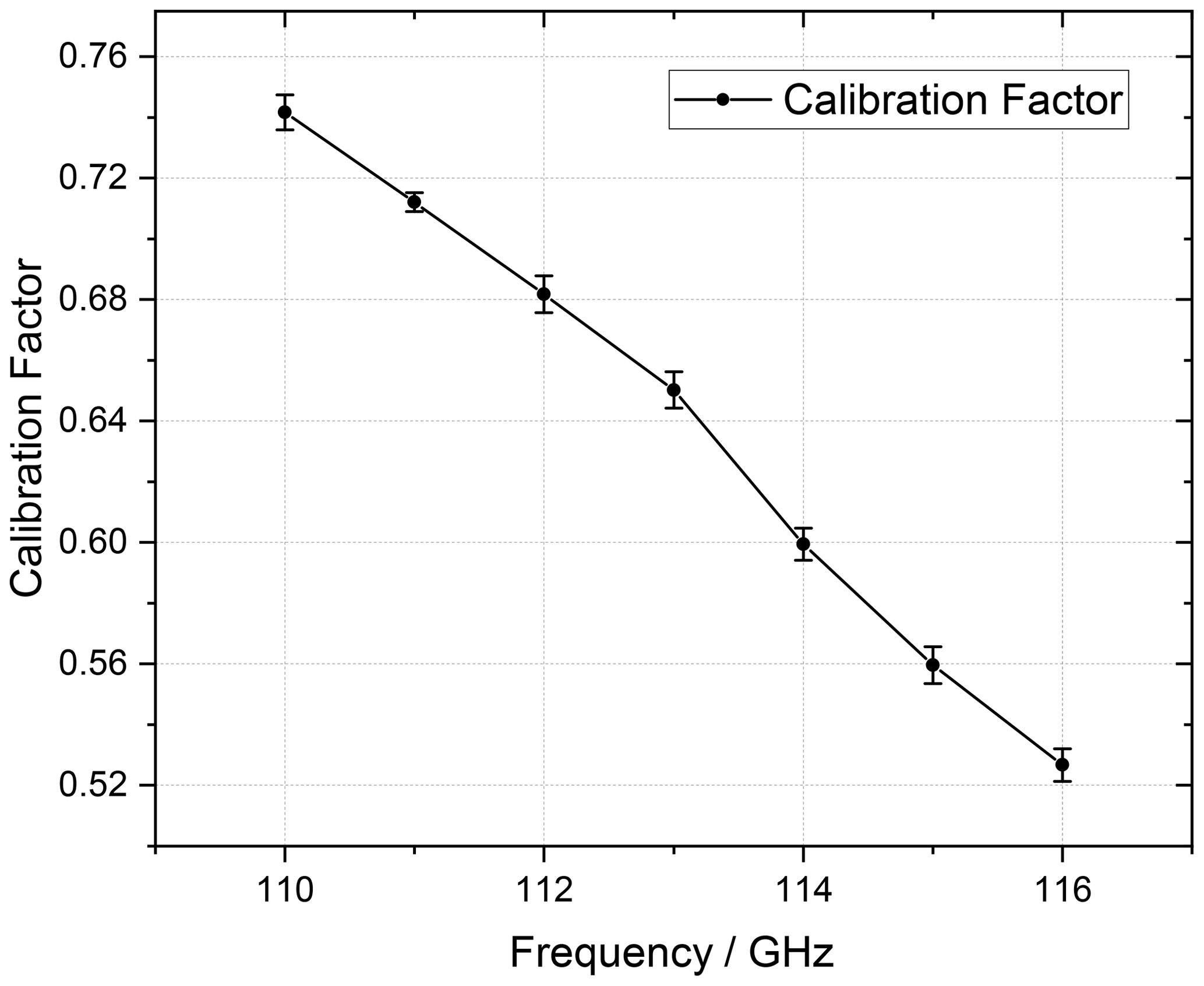
Figure 6Calibration factor of the R 900 thermistor mount 45776H and measurement repeatability (standard deviation) in the direct transfer system.
The calibration factor of the R 900 thermistor mount including measurement uncertainties is shown in Fig. 7, both from calibration with a microcalorimeter set-up and a direct transfer system. A good agreement between both methods, with differences around 0.012 is observed.

The measurement uncertainty for the generalized efficiency of the waveguide thermoelectric DUT sensor obtained with the direct transfer system in the frequency range of 110 to 170 GHz is 0.052. The significant uncertainty sources are:
-
uncertainty of the transfer standard
-
mismatch factors
-
measurement repeatability
-
resolution of multimeters
-
harmonic content of the RF source
The mismatch factors consist of uncertainty due to mismatch of the transfer standard with the signal source and mismatch of the DUT sensor with the signal source at the measurement port (EA Laboratory Committee, 2022). The uncertainty has been evaluated based on the Guide to the Expression of Uncertainty in Measurement (GUM:1995) (JCGM, 2008).
Both the direct transfer system and the microcalorimeter set-up are methods to calibrate millimeter wave power sensors. Microcalorimeter measurements require long measurement times (weeks to months), while the uncertainty is quite low. The calibration with a direct transfer system is much faster (hours to days), but the uncertainty is somewhat higher when compared to the microcalorimeter set-up. Figures 8 and 9 show the expanded measurement uncertainty (k=2) for both methods. The measurement uncertainty of the generalized efficiency of the waveguide thermoelectric sensor is quite comparable with the calibration factor of the thermistor mount.
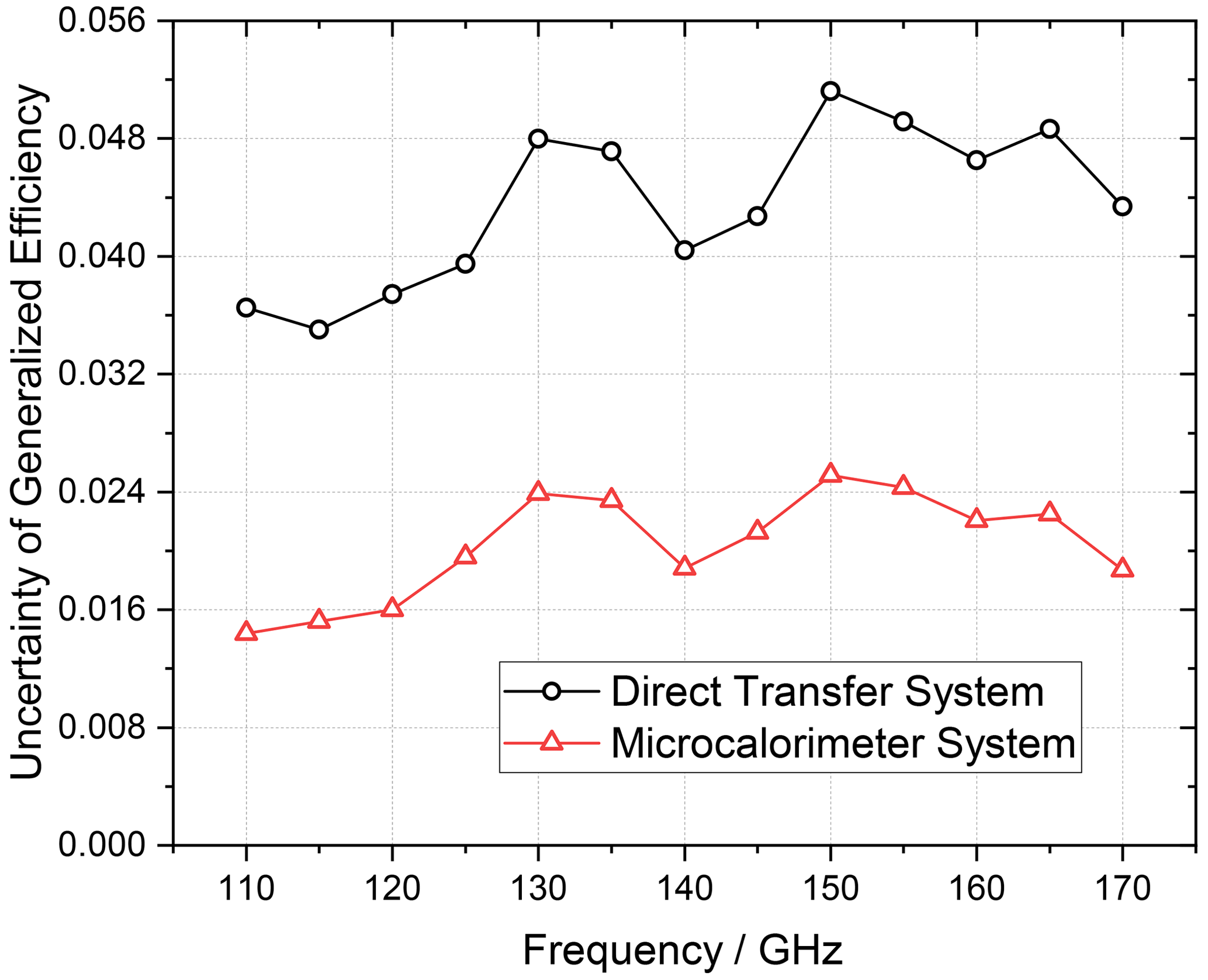
Figure 8Comparison of the measurement uncertainty of the generalized efficiency of the waveguide thermoelectric sensor.
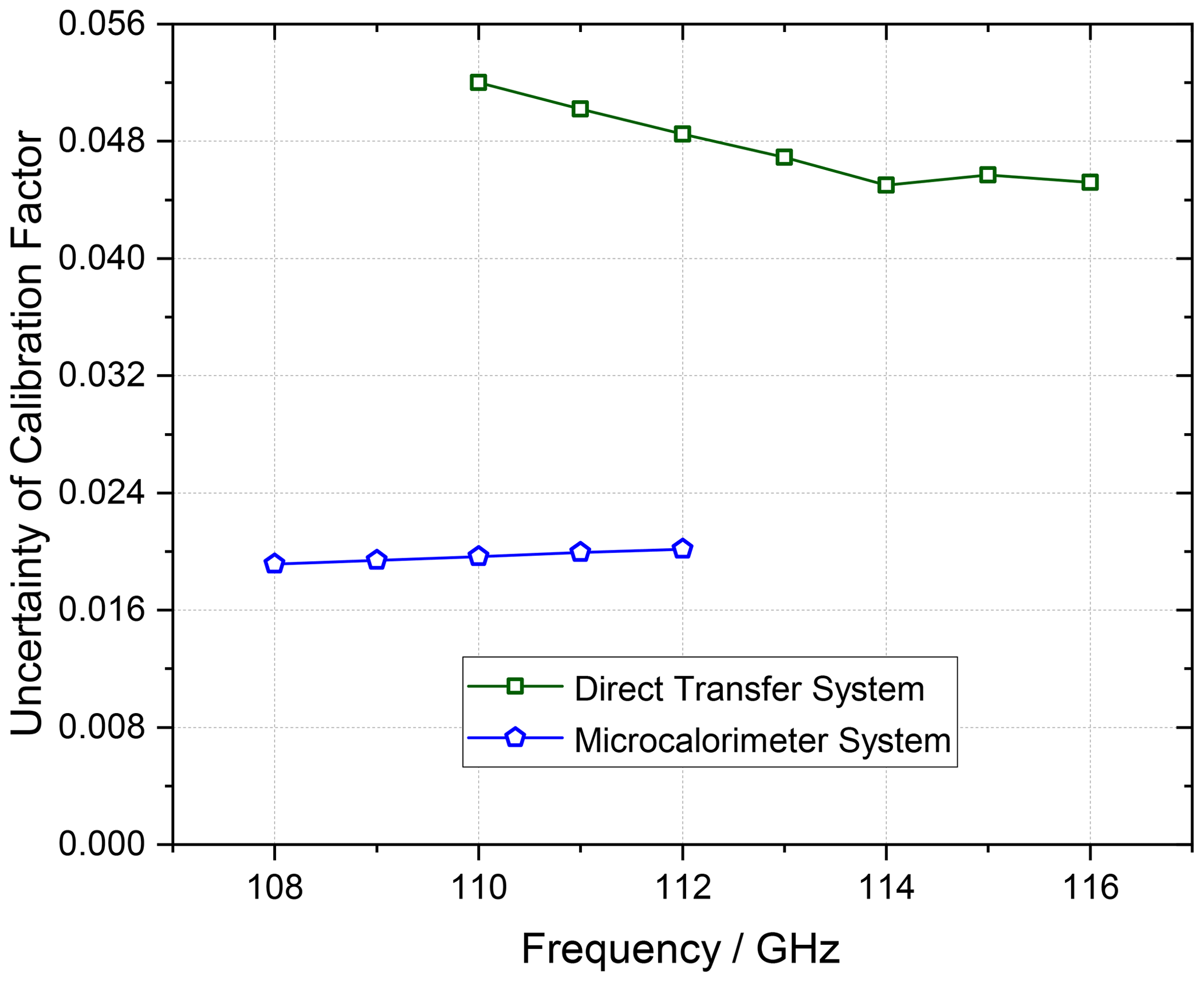
Figure 9Comparison of the measurement uncertainty of the calibration factor of the R 900 thermistor mount.
The generalized efficiency of the waveguide thermoelectric sensor has been calculated and the sensor was used as transfer standard in the millimeter wave frequency of 110 to 170 GHz. The measurement uncertainty at the direct transfer system was 0.052 in the operating frequency range. The generalized efficiency in the direct transfer system has been verified with the microcalorimeter system, and a good agreement can be observed. The generalized efficiency was used directly to determine the calibration factor of the other types of power sensor, i.e., calorimeter-style power meter and thermistor mount. Accordingly, the waveguide thermoelectric sensor with its generalized efficiency can be used as a transfer standard to calibrate different types of power sensors in the direct transfer system to determine both the generalized efficiency and the calibration factor. Using suitable adapters (tapers) offers the possibility to extend the frequency range as long as single mode operation is guaranteed.
Software codes and research data are not available for the presented work, but all results can be reproduced with the parameters and equations given here.
WKPA, KK, and JR conceived the presented idea. WKPA wrote the manuscript. JR and WKPA carried out the measurement and analyzed the data. All authors discussed the results and contributed to the final manuscript.
The contact author has declared that none of the authors has any competing interests.
Publisher’s note: Copernicus Publications remains neutral with regard to jurisdictional claims made in the text, published maps, institutional affiliations, or any other geographical representation in this paper. While Copernicus Publications makes every effort to include appropriate place names, the final responsibility lies with the authors.
This article is part of the special issue “Kleinheubacher Berichte 2022”. It is a result of the Kleinheubacher Tagung 2022, Miltenberg, Germany, 27–29 September 2022.
The authors would like to thank Thomas Kleine-Ostmann for his support.
This research has been supported in part by the European Association of National Metrology Institutes (EMPIR Project 18SIB09 TEMMT).
This open-access publication was funded by the Physikalisch-Technische Bundesanstalt.
This paper was edited by Lars Ole Fichte and reviewed by Georgiana Rosu and one anonymous referee.
Brunetti, L., Oberto, L., Sellone, M., and Vremera, E. T.: Comparison Between Thermoelectric and Bolometric Microwave Power Standards, IEEE T. Instrum. Meas., 62, 1710–1715, https://doi.org/10.1109/TIM.2013.2253914, 2013. a
Celep, M. and Stokes, D.: Characterization of a Thermal Isolation Section of a Waveguide Microcalorimeter, IEEE T. Instrum. Meas., 70, 1–7, https://doi.org/10.1109/TIM.2021.3084306, 2021. a
Chung, N. S., Shin, J., Bayer, H., and Honigbaum, R.: Coaxial and Waveguide Microcalorimeters for RF and Microwave Power Standards, IEEE T. Instrum. Meas., 38, 460–464, https://doi.org/10.1109/19.192327, 1989. a
Cui, X., Meng, Y. S., Shan, Y., and Li, Y. (Eds.): New Trends and Developments in Metrology, Microwave Power Measurements: Standards and Transfer Techniques, IntechOpen, https://doi.org/10.5772/60442, 2016. a
EA Laboratory Committee: Evaluation of the Uncertainty of Measurement in calibration, European Accreditation, https://european-accreditation.org/wp-content/uploads/2018/10/EA-4-02.pdf (last access: 21 January 2023), 2022. a
EverythingRF: Waveguide Sizes, EverythingRF, https://www.everythingrf.com/tech-resources/waveguides-sizes, last access: 15 December 2022. a
Fantom, A. (Eds.): Radio Frequency and Microwave Power Measurement, Peter Peregrinus Ltd, London, United Kingdom, ISBN 0863411207, 1990. a, b, c, d
JCGM: Evaluation of measurement data – Guide to the expression of uncertainty in measurement, JCGM 100:2008 GUM 1995 with minor corrections, https://www.bipm.org/documents/20126/2071204/JCGM_100_2008_E.pdf (last access: 26 January 2023), 2008. a
Judaschke, R. H., Kuhlmann, K., Reichel, T., and Perndl, W.: A W-Band Thermoelectric Power Transfer Standard, in: Proceedings of 29th Conference on Precision Electromagnetic Measurements, Rio de Janeiro, Brazil, 24–29 August 2014, IEEE, 756–757, https://doi.org/10.1109/CPEM.2014.6898606, 2014. a, b, c
Judaschke, R. H., Kuhlmann, K., Reichel, T. M., and Perndl, W.: Millimeter-Wave Thermoelectric Power Transfer Standard, IEEE T. Instrum. Meas., 64, 3444–3450, https://doi.org/10.1109/TIM.2015.2454632, 2015. a, b, c
Reichel, T.: Power sensor with 1 mm coaxial connector covers the frequency range from DC to 110 GHz without interruption, News Rohde Schwarz, Rohde and Schwarz, 23–25, ISSN 0028-9108, 2013. a
Vollmer, E., Ruhaak, J., Janik, D., Peinelt, W., Butz, W., and Stumper, U.: Microcalorimetric Measurement of the Effective Efficiency of Microwave Power Sensors Comprising Thermocouples, in: Proceedings of Conference on Precision Electromagnetic Measurements, Boulder, CO, USA, 27 June–1 July 1994 IEEE, 147–148, https://doi.org/10.1109/CPEM.1994.333409, 1994. a
Weidman, M. P.: Direct Comparison Transfer of Microwave Power Sensor Calibration, NIST Technical Note 1379, Natl. Inst. Stand. Technol., Boulder, Colorado, https://nvlpubs.nist.gov/nistpubs/Legacy/TN/nbstechnicalnote1379.pdf (last access: 14 December 2022), 1996. a, b, c
- Abstract
- Introduction
- Study of the Generalized Efficiency in the Direct Transfer System
- Measurement Setups
- Measurement Results
- Evaluation of Measurement Uncertainty
- Conclusions
- Code and data availability
- Author contributions
- Competing interests
- Disclaimer
- Special issue statement
- Acknowledgements
- Financial support
- Review statement
- References