 | 19 Sep 2019
Cooperative radar with signature method for unambiguity
Simon Müller
Andreas R. Diewald
The increasing availability of off-the-shelf high-frequency components makes radar measurement become popular in mainstream industrial applications. We present a cooperative FM radar for strongly reflective environments, being devised for a range of up to approx. 120 m. The target is designed with an unambiguous signature method and satisfies coherence. A prototype is built with commercial semiconductor components that operates in the 24 GHz industrial, scientific and medical band. First experimental results taken in sewage pipes are presented, using the target prototype and a standard FMCW radio station. An overview on four data acquisition procedures is given.
- Article
(6299 KB) - Full-text XML
- BibTeX
- EndNote


Cooperative radar systems are also known as secondary radars. In contrast to conventional radar, their purpose is not to detect passive scatterers but they are able to track an active object. Classical configurations utilize combined principles of communication link and radar-based measurement. Secondary radar applications are mainly found in military sectors, aviation, navigation and partly in industry, here almost confined to large-distance applications. With increasing availability of compact radar electronics in the preceding few years, the trend of conventional radar technology becoming increasingly popular seems likely to be devolved also to cooperative radar. The general concept of cooperative radar contains a catalog of realization methods. Challenging aspects for development are the requirements of unambiguity and coherence.
In the following sections, a concept for a radar target is presented that offers coherence and can be used in one measurement system amongst several identical targets. Due to carrier suppression, a higher gain in comparison to backscatter targets is possible allowing for extended range or utilization in environments with extremely high passive clutter. As the target is devised as a kind of “listener”, clock synchronization is not necessary nor processing delays associated with a data link occur. In consequence, the target to be presented is widely independent of the base station to be used which is in the case of range measurement usually a FM radar system.
Over the years, many different functional approaches have been developed as realizations to tag a certain target. Depending on case-related requirements, properties of the secondary radar principles differ in achievable range and angular interval, total and relative resolution. Also environmental impact is not negligible and leads to the choice of a particular technology or its enhancements. The common technologies can be classified into passive or active devices, the last-mentioned may be redivided either by means of functional likeliness in base station and target, or by presence of a data link. However, a distinct categorization is not necessarily convenient or beneficial.
The apparently most simple tag is a retro-reflective array or Van Atta reflector array (Sharp and Diab, 1960) which increases the radar cross section (RCS) of a target, comparable to a corner reflector but with frequency dependency. Based on retro-reflectors, switching modulators allow for the modulation of the RCS. This accordingly causes a modulation of the reflected signal which helps to simplify the detection of a so-marked object (Thornton and Edwards, 1998, 2000). Kossel et al. (2000) code one or both transmitted and reflected signal with a bit sequence, introducing a communication link between now multiple base stations and targets. The shown concepts still suffer from the path dependency, known from the Radar equation, by the fourth power of range. Schmid et al. (2011) and Dadash et al. (2017a, b) apply a phase shift modulation or transfer a bit stream by frequency shift keying as unambiguous modulation (Schreiblhofer et al., 2017). By achieving a better decoupling between the target's transmit and receive paths, gain could be increased, as figured out by Vossiek and Gulden (2008) and Strobel et al. (2013), reducing path attenuation to approximately the square of range by stimulating an oscillator with the received signal. Since the phase of the output and stimulus drift by time, this principle (amongst others) is strictly speaking not coherent but sufficiently synchronized in phase for a short period.
Another group of secondary radar uses parallel data link for synchronization of two widely equal equipped units. This usually requires a separate transmission channel (Feger et al., 2012; Schreiblhofer et al., 2014). In the concept of synchronized units, each unit is equipped with an own oscillator that is clocked independently, giving reason for additional effort on synchronization (Roehr et al., 2008; Stelzer et al., 2008). Besides the advantage of the R−2 dependency known from Friis equation for the signal amplitude, coherence is strictly denied meaning that range is usually estimated by combining spectra of both units for one-way time of flight measurements or with exactly known latencies for a round-trip time of flight measurement.
Network based localization involves several nodes detecting distance among each other or triangulate the position of passive targets by processing FMCW ramps of participating other transmitters (Ebelt et al., 2014; Frischen, 2017).
Briefly summarized, the given concepts require either a huge amount of effort on synchronization of the involved units or on creation of identification codes for the single targets. Caused by a certain signal processing delay, coherence is lost or is only approximately given because of makeshift methods. In addition, the commonly used modulation schemes of phase or rectangular amplitude modulation cause a wide-spread spectrum due to their characteristic harmonics (Thornton and Edwards, 1998).
The most simple concept of an active responder simply amplifies the signal received from a classical FMCW radar. Its components are a receiving antenna, RF amplifier (optional with variable gain) and a transmit antenna as shown in Fig. 1. The base station emits a signal y1(t) represented by
with signal amplitude A, time-dependent frequency ω(t)=2πf(t) and start phase φ0 of the oscillator. ω(t) is assumed as a linear sawtooth ramp. In practice, a gain of approximately 20 to 30 dB is realizable due to parasitic coupling from the amplified output back to the input.
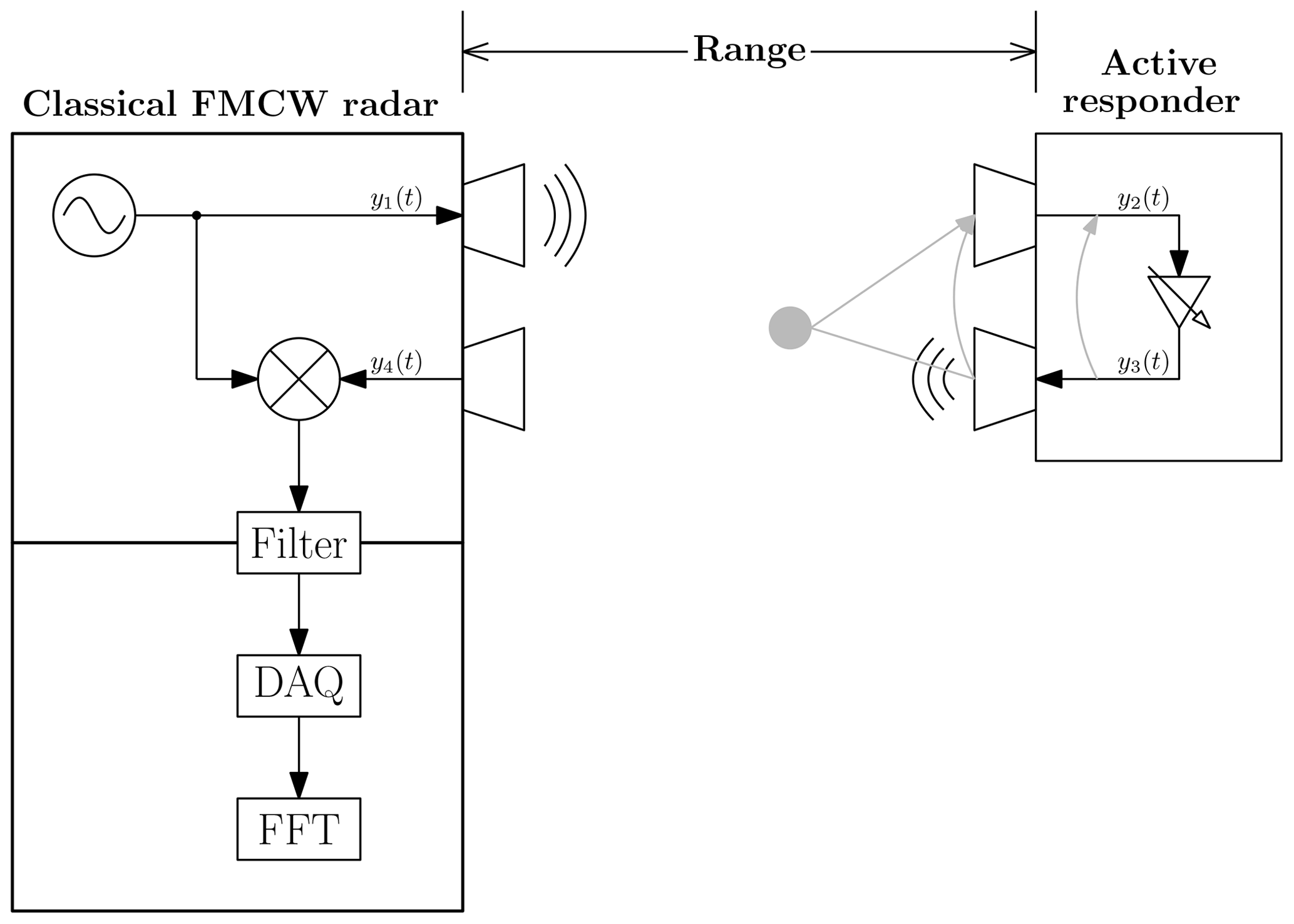
This feedback may be caused directly on the device by radiation from transmission lines or antenna coupling, or through passive scatterers in the signal path, located close to the front of the responder, as indicated in Fig. 1 (gray paths). Antenna coupling could be reduced by utilization of orthogonal polarizations for receiving and transmitting paths. Higher gain may result in instability when the closed-loop gain exceeds unity, driving the amplifier chain into saturation.
The major advantage of this simple concept is basically the usability of a classical FMCW radar transceiver when the additional signal delay caused by the described electronics is considered in signal processing. Thus, range and Doppler measurement is possible:
Neglecting the additional delay on transmission lines of the responder, the input signal at the receiver is equal to the passive case. The amplitude gain G of the reflector is similar to a certain radar cross section, resulting in the received signal y4(t) with amplitude D (under consideration of path attenuation),
where ToF is the one-directional delay time of the signal along the range R. Downconversion is described as calculation of the product of transmitted and received signal, followed by lowpass filtering with the transfer function LPF() eliminating the RF portion of the received signal, which leads to
and resp.
The filter output is then digitally processed. In the setup presented by now, no advantage is reached in comparison to a classical primary radar approach under few circumstances. Although the equivalent radar cross section of the target is increased, the active target may not be detected in a marginal number of cases if the environment is highly reflective or if the actively reflected power is not sufficiently higher or still less than clutter. Figure 2 illustrates the amplitude spectrum of the reflective environment (blue) and varying amplitudes of the target reflection (red) which could fluctuate between not detectable (case 1) and detectable with low precision (poor signal-to-“noise” ratio, case 2). The spectral amplitude relations Utarget, Uenv(ironment) could hence be described as
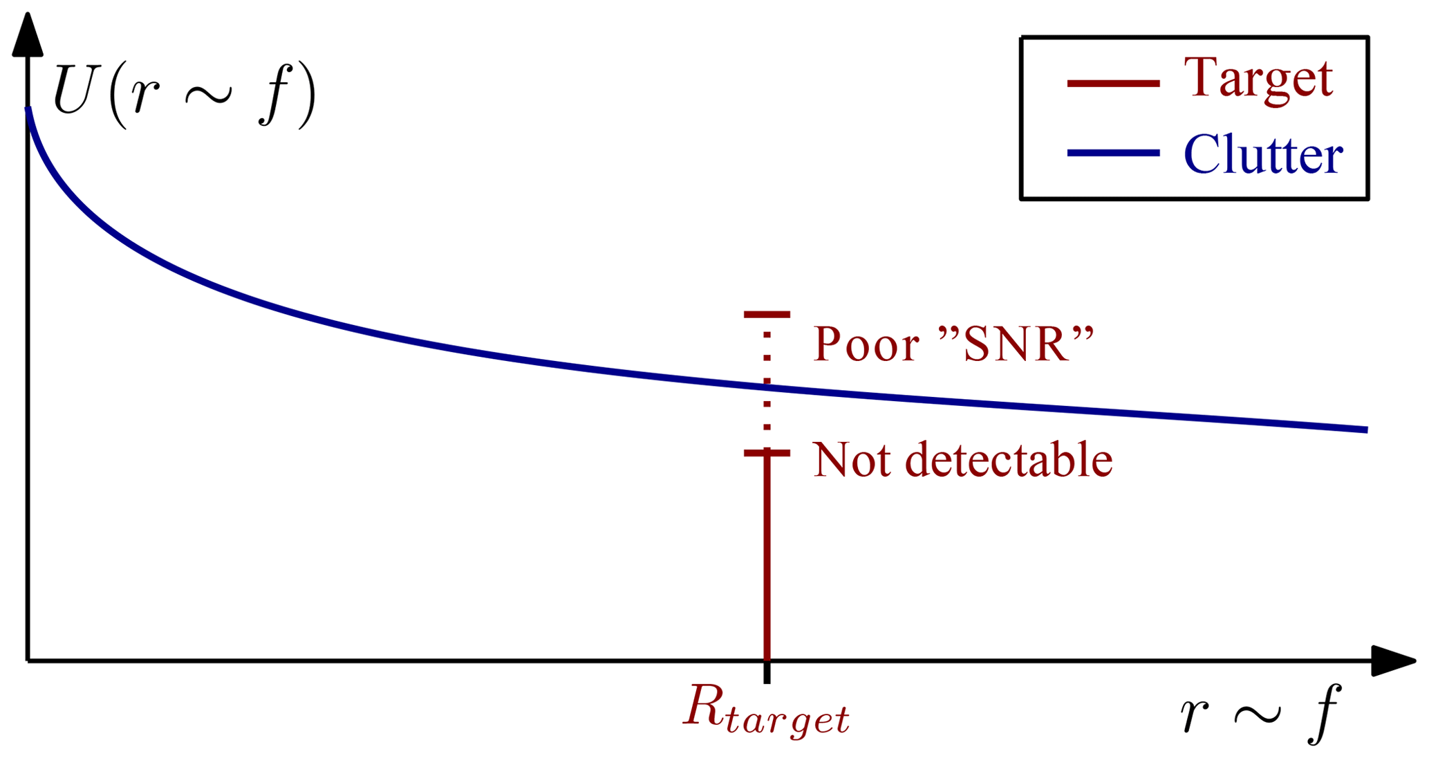
Figure 2Baseband amplitude spectra of a single target (red) and clutter of strongly reflective environment (blue).
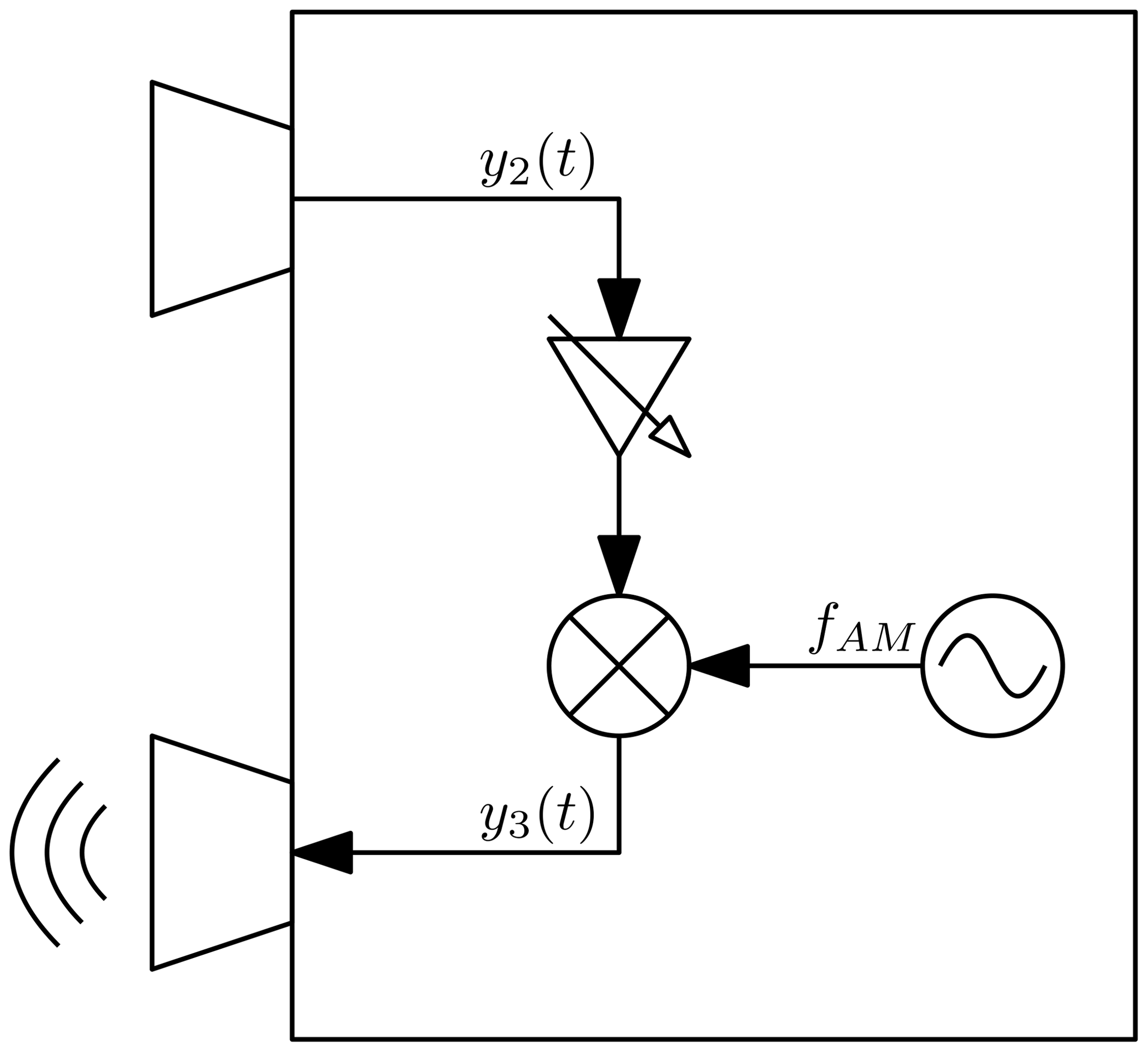
3.1 Amplitude modulation
In order to increase the quality of the active signal, the active responder is now modified by adding an additional oscillator and mixer. The received signal is amplified and amplitude modulated with an envelope frequency ωAM. No changes are made for the frontend of the measurement system. The principle that is now applied to the responder is shown in Fig. 3. The choice of a correct envelope frequency is important to achieve full advantages which are derived from theory. Assuming the same signal y1(t) as before being transmitted by the measurement system (Eq. 1), also the signal y2(t) received by the reflector remains equal. Its output y3(t) is modified, resulting in a modified input signal y4(t) to the downconverter at the base station of the measurement system:
Multiplication of transmitted and received signals leads to:
and resp.
Comparison of Eqs. (9) and (4) leads to the intended effect of the AM oscillator. Equation (9) consists of the product of an amplitude information, an oscillation proportional to the round-trip time of flight (which is still the wanted signal), and an oscillation at ωAM. The first and second multipliers are already known from Eq. (4). The third signal component, which was the envelope in the high-frequency path, is unaffected by downconversion. Although the time of flight, ToF occurs in this term, it has no impact on its frequency. Instead, phase changes with ToF and therefore with the target range. Thus, the meaning of “envelope” changes radically after downconversion: The constant oscillation at ωAM now becomes a carrier, being modulated with the range information coded in the second component of Eq. (9). This may now be called envelope. As illustrated in Fig. 4, their product generates a pair of frequency bins in a distance of ±ft around fAM. ft is the frequency deviation caused by the round-trip time of flight to the target. By choosing a well-suited frequency for the AM oscillator, the active target is clearly separated from passive clutter. It should be chosen at least high enough to avoid an overlap of the active target's bins and the expected clutter spectrum. In case that several targets are used in the same system, unambiguity of targets is is either given by the choice of a unique RF envelope for every single tag, or due to the spectral symmetry at a common baseband carrier frequency. When using the first strategy, sufficient channel pitch should be considered to avoid overlaps of spectral lines of different targets. In the other case, corresponding bins are matched during data processing.
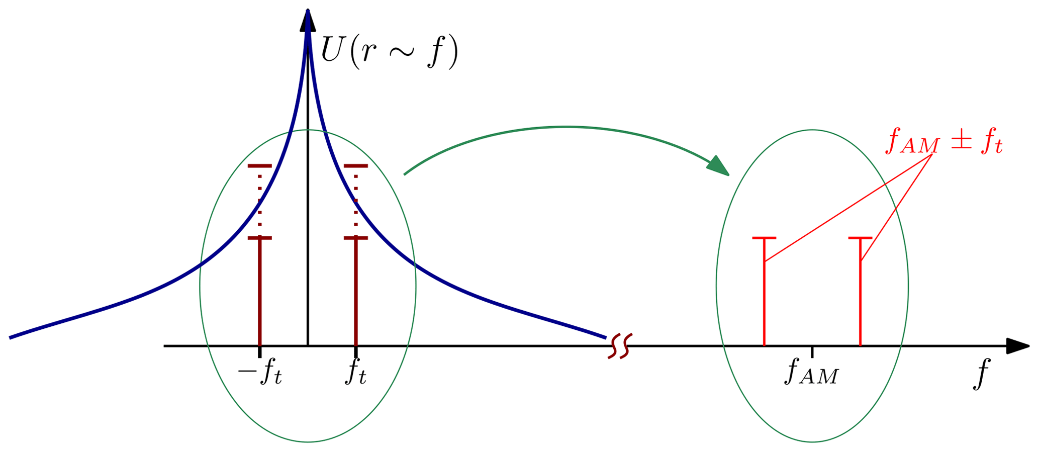
Figure 4Frequency shift in the baseband due to amplitude modulation separates the wanted signal from clutter (blue line).
3.2 Extraction of range and Doppler information
The classical radar parameters, range and Doppler shift may be accessed by observing the differential allocation of both lower and upper frequency points in ul(t) and uu(t). By splitting Eq. (9), the frequency bins occur at
Let ω(t) be a linear chirp, with duration ΔTc and bandwidth BW . The calculated range R becomes
with fu and fl being the two frequency bins represented by the time-dependent summands of the cosine function. This form is close to classical radar besides the constant division by four instead of two. This is due to the total frequency difference – the lower frequency point is indeed the negative frequency point for classical radar shifted by fAM.
We consider the summands of the cosine arguments in ul(t) and uu(t) depending on ToF to determine the influence of Doppler effect. A movement of the target causes a variation in time of flight. However, a slight range variation in the scale of the wavelength of ω(t) would not lead to a significant change of fu nor fl. We introduce the τ-dependent time of flight and extend Eqs. (10) and 11.
First and fourth summands in the cosine function are identified as constant in τ, the third summand causes equal effects on both Eqs. (14) and (15). A differential treatment leads to the wanted dependency for the Doppler as phase modulation ΔΦ(τ):
This means, the signal itself is strictly seen non-coherent, but the differential treatment of the two frequency points restores coherence and keeps both range and Doppler parameters without degradation of precision.
3.3 Data acquisition
Four acquisition techniques from brute-force to more extensive methods are discussed. Benefits and disadvantages are shown for direct sampling of the downconverted signal and the utilization of various principles of additional conversion.

3.3.1 Direct sampling
The apparently most primitive way to digitize is sampling of the complete spectrum (Fig. 5a). This procedure requires fast-sampling converters. Under consideration of the Nyquist theorem, sampling frequency Fs must exceed at least twice the maximum allowable frequency in the baseband spectrum, fu, which depends on the modulation frequency fAM and the furthermost detectable range Rmax. Additional sharp filtering must be taken into account to suppress any distortion from the second Nyquist zone. Remember the wanted signal is placed in the upper spectral region of the first Nyquist zone and frequencies above 0.5Fs are mirrored – poorly attenuated interferences in the roll-off region of a filter would possibly occur nearby the wanted signal. A further aspect to be considered is that the spectral room of interest is small in comparison to the full ADC bandwidth in this scenery, resulting in a large excess of data without sourcing additional information but requiring increased resources for data processing. This still allows for acquisition of passive clutter.
3.3.2 Undersampling
The next approach works on a lower sampling frequency that causes the wanted signal range to occur in an upper Nyquist zone, for practical reasons in the second, as illustrated in Fig. 5b, or third. This requires stronger roll-off and an even smaller passband of the input filter which has now become a bandpass filter. This is due to the decreased frequency bandwidth of the slow-sampling ADC. Care must be taken to choose a converter that allows the desired frequency range at its analog inputs since most ADCs are limited in bandwidth due to matching of their analog input stages to their maximum specified sampling frequency. The outer limits of the expected frequency range must be invariable and known well for a correct choice of Fs and the filter design. If all requirements are satisfied, this variant is seemingly a good compromise between development and BOM cost vs. computing time due to the reduced availability of raw data without loss of information.
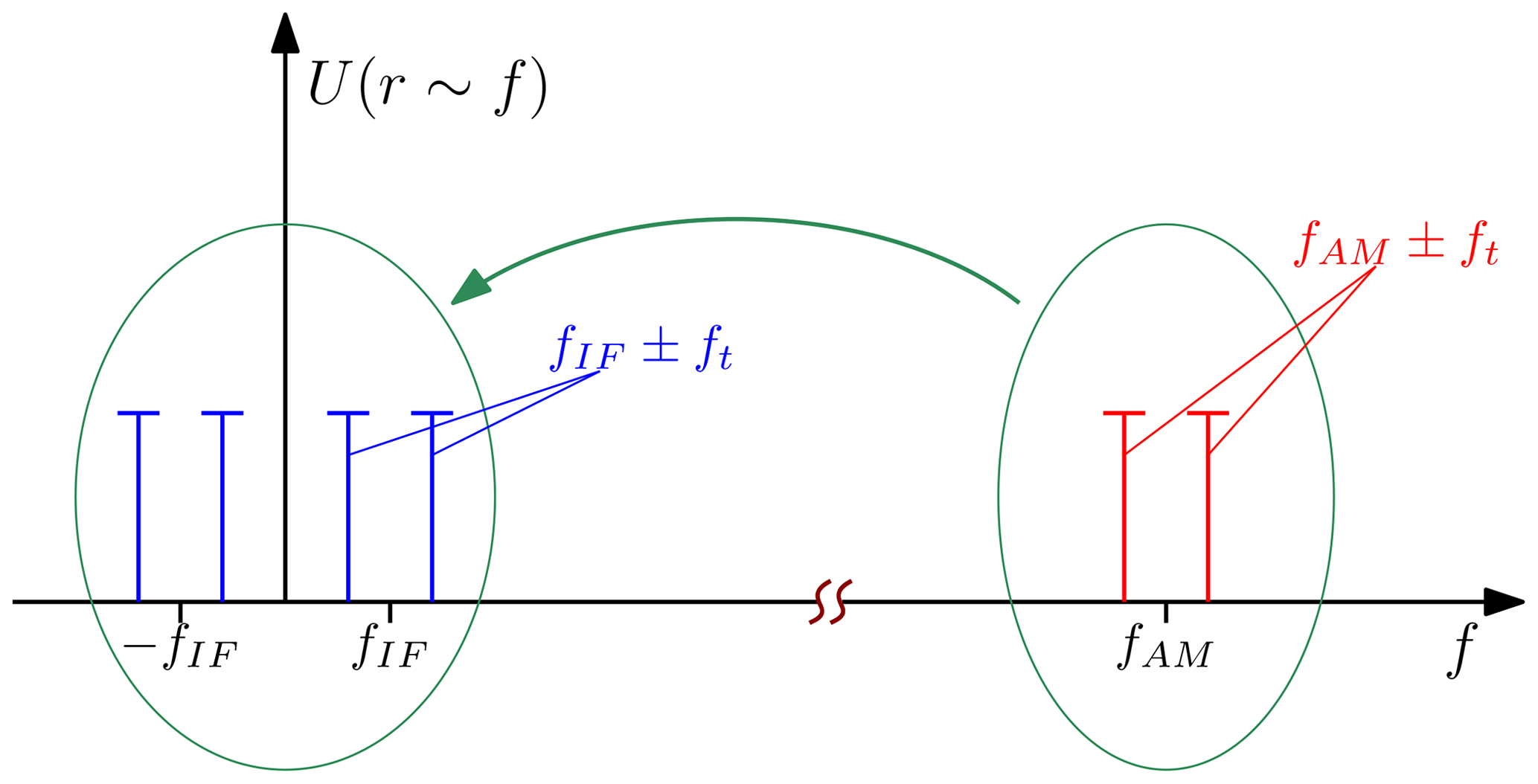
3.3.3 Secondary downconversion
The next alternative is in the result related to the undersampling method. This variant needs an additional local oscillator at fdown to mix the two frequency bins surrounding fAM into a lower intermediate band around fIF (Fig. 6). Two options are possible:
Case 1 is shown in Fig. 5c. The secondary downconversion requires the highest effort on hardware but keeps further development simpler since most of the single components are easier adaptable if any parameters of the overall system are changed: Purchasable oscillators and mixers prevalently offer a large or programmable bandwidth while AD converters are generally stronger restricted in the important frequency specifications.
3.3.4 Self multiplication
If multiple targets operate with different carrier frequencies in one overall system, the principles shown above (besides direct sampling) are tendentiously unsuited since all targets are distributed around several baseband carriers. Due to the limited bandwidth at undersampling and secondary downconversion, the maximum number of targets is limited considering the allowed spectral range. Otherwise, unambiguous assignment will become an issue in data processing due to probable overlap of neighboring target bin pairs at unexpectedly high ranges. In this case, the self multiplication as illustrated in Fig. 5d is an adequate way. The schematic is close to the secondary downconversion, but both inputs of additional the mixer are tied together. The conversion translates fAM to f=0. This shifts the lower bin of each target into the negative frequency half-plane. The expected output of a classical radar ranging to a conventional passive scatterer is recovered, but now for active targets while passive clutter is still eliminated.
3.4 Prototype
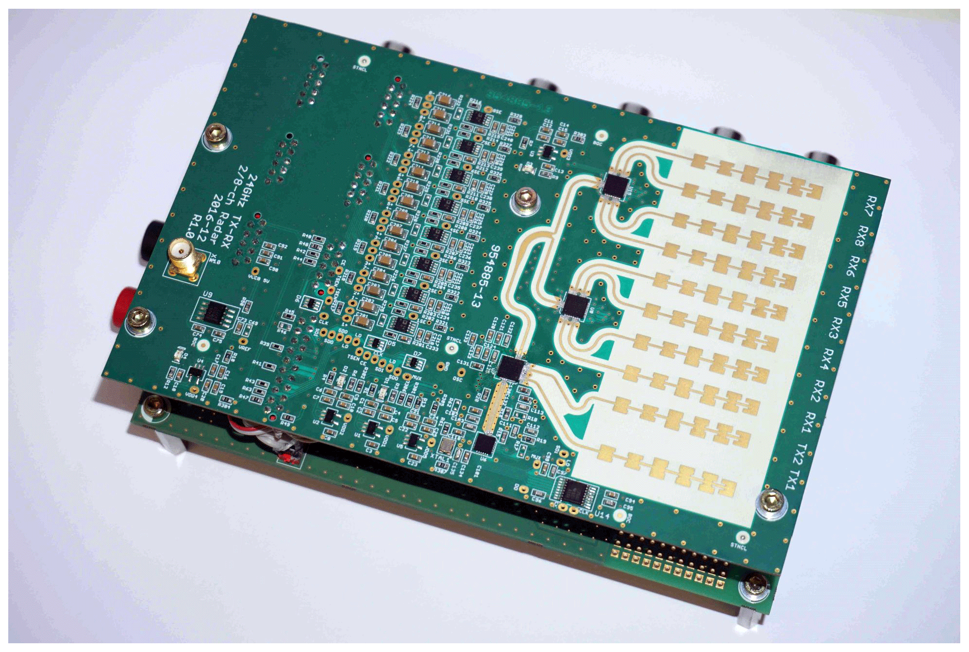
The RF path of the base station is a universal transceiver with two TX and eight RX channels. A picture is given in Fig. 7.
The platform operates in the 24 GHz ISM band with a maximum output power of less than 20 dBm EIRP. Thus, utilization is possible without official approval. The full bandwidth of 250 MHz is taken for FMCW mode. The output waveform ω(t) is a linear sawtooth ramp. Currently only one channel in each direction is in use. The first arrangement of the active responder is built up as a modular setup. It consists of several components, each one representing a certain function. The working principle shown in Fig. 3 has been implemented by the use of several gain stages (manually adjustable gain), mixer, programmable waveform generator and antennas. All functions are built up as an own module to reduce development cost and to simplify design changes or modifications. Battery powered supply allows for mobility. Its large size will be reduced for later versions and is only due to modularity. Anyway, the prototype fits into an industry standard DN 200 pipe with nominal outer diameter of 200 mm (inner diameter approx. 190 mm) as depicted in Fig. 8.

Because the intentional area of operation is a strongly reflective environment, appropriate surroundings would be tunnels, ducts, or pipes. The last-mentioned are the suitable choice for the first tests since pipes are immediately available in a large number of sizes and different materials.
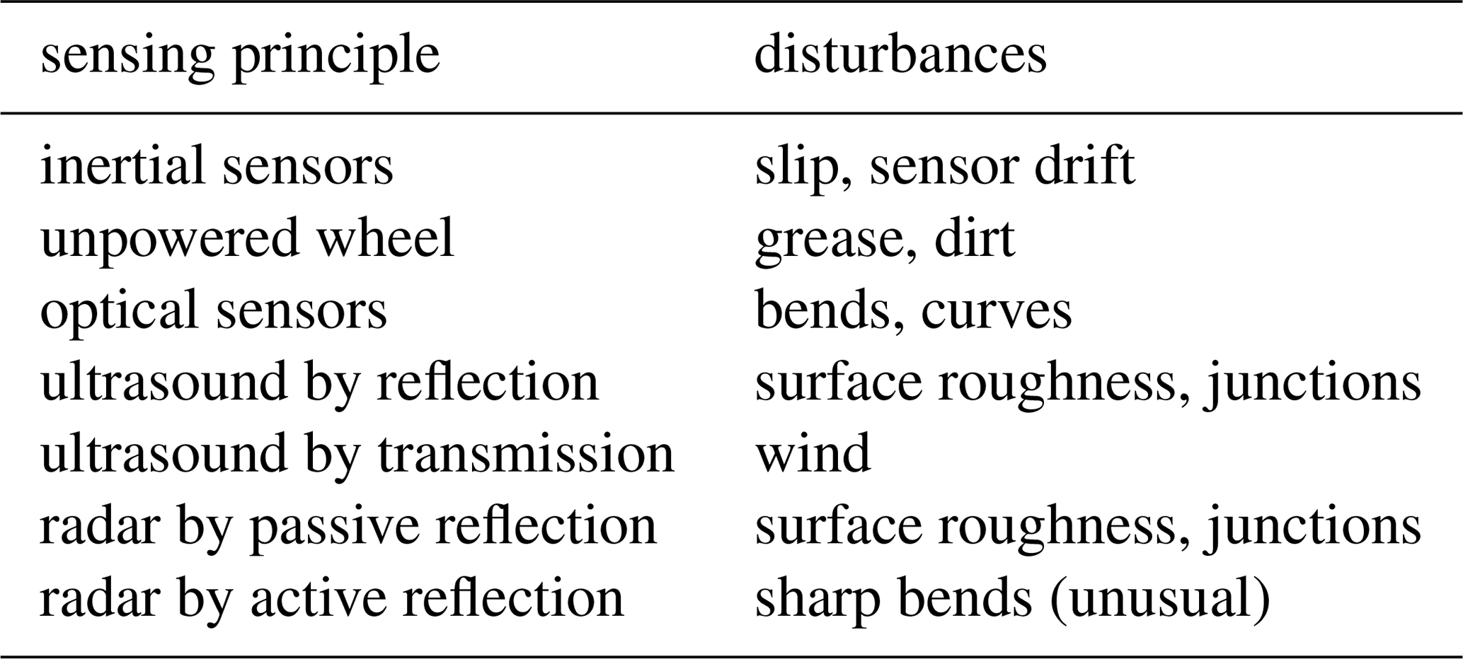
Distance measurement in pipes is generally seen a technical challenge for classical measurement processes. Disturbing effects are given by form (slight bends, junctions, roughness) or caused by environment (winds, dirt, greasy surfaces). An overview of sensing methods and disturbing effects is given in Table 1. Due to the shown insufficiencies, measurements are often performed manually with tape measure if start and end points are accessible for inspection. Several PVC sewers and fiberglass reinforced pipe liners have been at disposal for the measurements. Those are commercially used for the renewal of damaged waste pipes while still being in service during repair works. The measurement setup is illustrated in Fig. 9 and valid for any experiment discussed in the following. The localization of reference planes must be taken into account. Due to the length of transmission lines between receive and transmit antennas, offsets caused by electronic components are expected. Further constraint is the signal processing which was done with the direct sampling method. Due to traceability of the measurement by third-party participants, processing was performed live on a digital oscilloscope (Agilent DSO-X 2002A) with limited FFT resolution.

4.1 Experimental results
For the first experiment, the following setup was given. A pipe liner fabricated of fiber-glass reinforced plastic was laid out overground. Its length added up to 10.50 m which was determined manually with a tape measure. The active target was placed close to the end but still completely inside the tube while the base station was located at the opposite edge. For this static scene, radar measurement was started. The spectral lines in the baseband indicated a measured range of between the antenna planes of base station and target. The comparative manual measurement yielded for the distance between both antennas, yielding a total deviation of . Moistening of the inner surface of the pipe did not affect the observed result.
Next measurement was performed on a built-in PVC sewer being in service. Caused by weather, the pipe contained some rain water and condensate that day. The same proceeding as mentioned above was applied. The manual reference measurement gave a total length for this sewer of . Due to accessibility, the tape measure was pulled through the pipe with a robot. The antenna distance was . The radar measurement showed an error of or between both antenna planes.
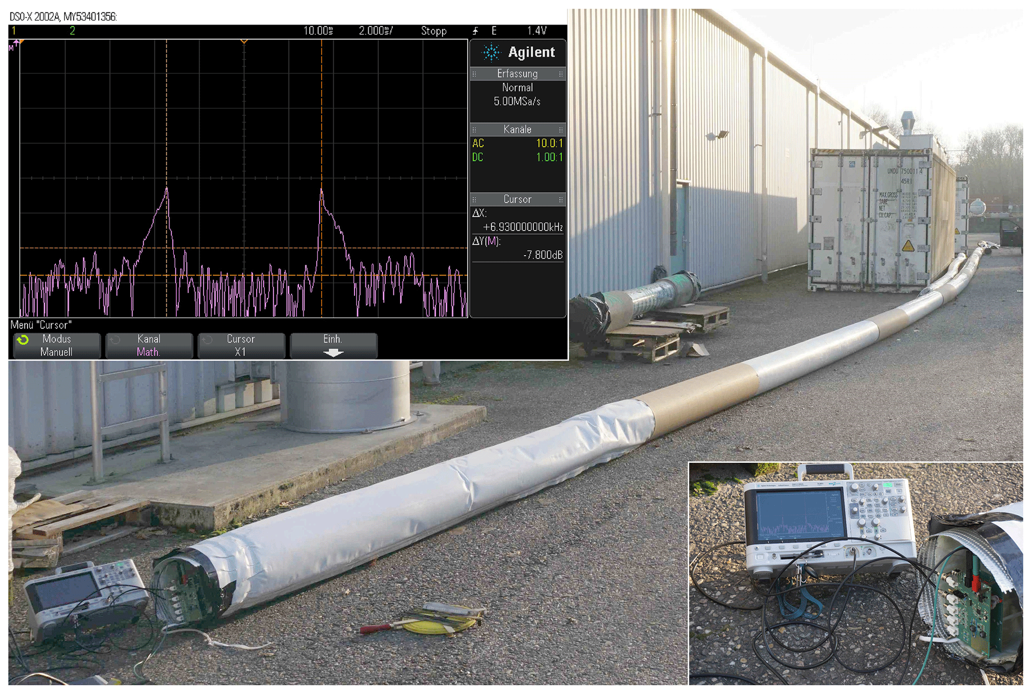
The third experiment was set up overground on a fiber-glass reinforced pipe liner. Direct line of sight between both ends was obstructed due to a wide curve in the middle of the pipe (see Fig. 10).
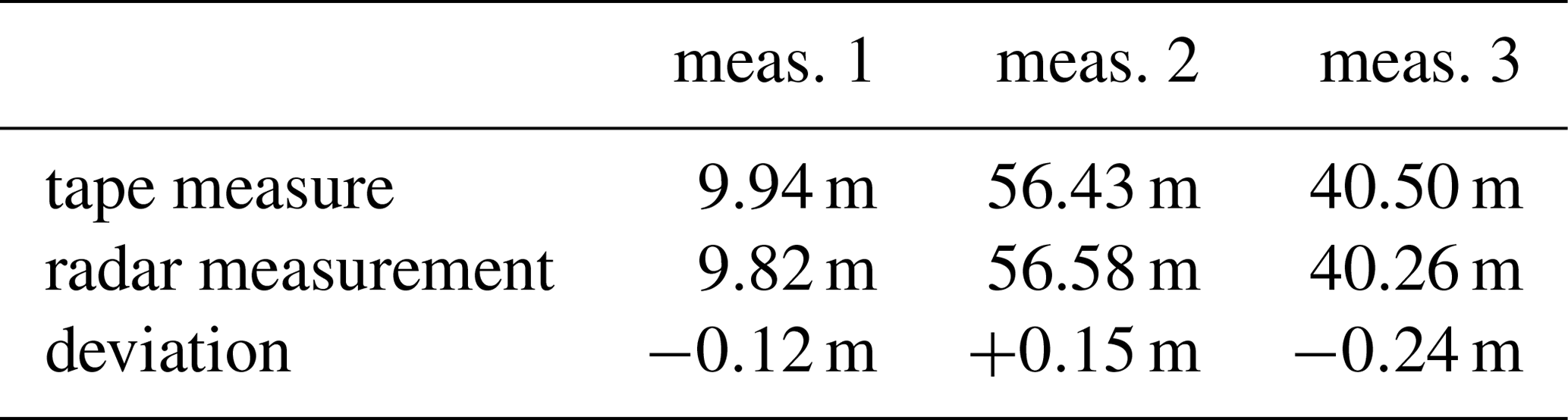
The amplitude spectrum clearly shows multipath propagation as becomes visible by spread spectral lines with fading flanks to higher frequency deviations from the baseband carrier. This is negligible since the direct transmission is the fastest and only the inner flanks of the measured spectral lines are relevant for length determination. The measured deviation exceeded the results of the prior measurements, and was at and . For comparison, the base station was then placed outside the cross-sectional area with the target unmoved. In this case, the recorded results were not reproducible since no measurable echo was received. A distinct baseband signal occurred even in the case that a measured pipe was bended when measuring inside the pipe liner. This effect suggests the ability for guidance of the electromagnetic wave along its inside while the cladding of the pipe acts as a barrier. For incidence angles almost tangential to its surface, this observation is what may be expected by theory. At least, the outer boundary surface of the plastic wall to the surrounding air acts as a transition from one material to a less refractive medium. All experimental results are are summarized in Table 2.
A cooperative radar method with unambiguity was presented. An active radar target allows for suppression of passive clutter. This makes the function principle useful for the detection of objects with a small passive radar cross section or if a target needs to be tracked amongst strongly reflective surroundings. Fields of application are range and Doppler measurements in environments that produce comparably high reflections, such as tunnels, ducts, or pipes. Theory was derived, a prototype has been presented and been used for the experimental proof of concept. The length of sewers had to be determined. The measurement results differed by less than 1.25 % of the reference value. Since no prior calibration was fulfilled, and signal processing was not matched well to the given system, there is obviously potential to increase range resolution of down to ΔR≈1 cm. An interesting aspect is the proven ability to also measure distance in bended pipes. Besides the implementation of adequate signal processing, future plans include the development of an improved target hardware with better signal decoupling and the ability for higher gains. By merging the existing functional modules, a severe reduction of size is aspired.
Underlying research data were recorded during the discussed experiments. Raw data were taken in cooperation with an industrial partner and therefore, if data are not mentioned in the article, protected by a nondisclosure aggreement.
ARD conceived of the present idea and the theory. ARD supervised the project. SM designed the RF-modules and put the complete electronics into operation and executed the measurements.
The authors declare that they have no conflict of interest.
This article is part of the special issue “Kleinheubacher Berichte 2018”. It is a result of the Kleinheubacher Tagung 2018, Miltenberg, Germany, 24–26 September 2018.
The authors would like to thank ANALOG DEVICES, especially Rudolf Wihl, Dirk Legens, Bernd Krätzig and Christian Eisenschmidt for the kind support.
This paper was edited by Jens Anders and reviewed by two anonymous referees.
Dadash, M. S., Hasch, J., Chevalier, P., Cathelin, A., and Voinigescu, S. P.: A W-band active millimeter-wave tag IC with wake-up function, in 2017 IEEE MTT-S International Microwave Symposium (IMS), 1531–1534, 2017a. a
Dadash, M. S., Hasch, J., and Voinigescu, S. P.: A 77-GHz active millimeter-wave reflector for FMCW radar, in 2017 IEEE Radio Frequency Integrated Circuits Symposium (RFIC), 312–315, 2017b. a
Ebelt, R., Hamidian, A., Shmakov, D., Zhang, T., Subramanian, V., Boeck, G., and Vossiek, M.: Cooperative Indoor Localization Using 24-GHz CMOS Radar Transceivers, IEEE T. Microw. Theor., 62, 2193–2203, https://doi.org/10.1109/TMTT.2014.2337281, 2014. a
Feger, R., Pfeffer, C., Scheiblhofery, W., Schmid, C. M., Langz, M. J., and Stelzer, A.: A 77-GHz cooperative secondary radar system for local positioning applications, in 2012 IEEE/MTT-S International Microwave Symposium Digest, 1–3, 2012. a
Frischen, A., Hasch, J., and Waldschmidt, C.: A Cooperative MIMO Radar Network Using Highly Integrated FMCW Radar Sensors, IEEE T. Microw. Theory, 65, 1355–1366, https://doi.org/10.1109/TMTT.2016.2647701, 2017. a
Kossel, M., Benedickter, H. R., Peter, R., and Bächtold, W.: Microwave backscatter modulation systems, in 2000 IEEE MTT-S International Microwave Symposium Digest (Cat. No.00CH37017), 3, 1427–1430, 2000. a
Roehr, S., Gulden, P., and Vossiek, M.: Precise Distance and Velocity Measurement for Real Time Locating in Multipath Environments Using a Frequency-Modulated Continuous-Wave Secondary Radar Approach, IEEE T. Microw. Theory, 56, 2329–2339, https://doi.org/10.1109/TMTT.2008.2003137, 2008. a
Schmid, C. M., Feger, R., and Stelzer, A.: Millimeter-wave phase-modulated backscatter transponder for FMCW radar applications, in 2011 IEEE MTT-S International Microwave Symposium, 1–4, 2011. a
Schreiblhofer, W., Schreiblhofer, S., Schrattenecker, J., Vogl, S., and Stelzer, A.: A High-Precision Long Range Cooperative Radar System for Rail Crane Distance Measurement, European Microwave Week, Rome, Italy, 2014. a
Scheiblhofer, W., Feger, R., Haderer, A., Scheiblhofer, S., and Stelzer, A.: Simultaneous localization and data-interrogation using a 24-GHz modulated-reflector FMCW radar system, in 2017 IEEE MTT-S International Microwave Symposium (IMS), 67–70, 2017. a
Sharp, E. and Diab, M.: Van Atta reflector array, IRE Transactions on Antennas and Propagation, 8, 436-–438, https://doi.org/10.1109/TAP.1960.1144877, 1960. a
Stelzer, A., Jahn, M., and Scheiblhofer, S.: Precise distance measurement with cooperative FMCW radar units, in 2008 IEEE Radio and Wireless Symposium, 771–-774, 2008. a
Strobel, A., Carlowitz, C., Wolf, R., Ellinger, F., and Vossiek, M.: A Millimeter-Wave Low-Power Active Backscatter Tag for FMCW Radar Systems, IEEE T. Microw. Theory, 61, 1964–-1972, https://doi.org/10.1109/TMTT.2013.2252915, 2013. a
Thornton, J. and Edwards, D. J.: Modulating retro-reflector as a passive radar transponder, Electron. Lett., 34, 1880-–1881, https://doi.org/10.1049/el:19981326, 1998. a, b
Thornton, J. and Edwards, D. J.: Range measurement using modulated retro-reflectors in FM radar system, IEEE Microw. Guided W., 10, 380–382, https://doi.org/10.1109/75.867857, 2000. a
Vossiek, M. and Gulden, P.: The Switched Injection-Locked Oscillator: A Novel Versatile Concept for Wireless Transponder and Localization Systems, IEEE T. Microw. Theory, 56, 859–866, https://doi.org/10.1109/TMTT.2008.918158, 2008. a