 | 17 Dec 2021
Innovative Differential Magnetic Localization Method for Capsule Endoscopy to Prevent Interference Caused by the Geomagnetic Field
Daisuke Anzai
Angelika Thalmayer
Georg Fischer
Jens Kirchner
Wireless capsule endoscopy is an established medical application for the examination of the gastrointestinal tract. However, the robust and precise localization of these capsules is still in need of further scientific investigation. This paper presents an innovative differential magnetic localization method for capsule endoscopy to prevent interference caused by the geomagnetic field. The effect of changing the orientation of the capsule on the localization process was also examined. Simulations using COMSOL Multiphysics with the superimposed geomagnetic field were performed. The Levenberg–Marquardt algorithm was applied in MATLAB to estimate the position and orientation of the capsule. Comparing the proposed differential method with the absolute magnetic localization method under ideal conditions, the mean position and orientation errors were reduced by three orders in magnitude to less than 0.1 mm and 0.1∘ respectively. Even if sensor non-idealities are considered, the simulation-based results reveal that our proposed method is competitive with state-of-the-art geomagnetic compensation methods for static magnetic localization of capsule endoscopes. The achieved localization accuracy by applying the differential method is not dependent on the rotation of the localization system relative to the geomagnetic flux density under the made assumptions and the impact of the magnet orientation is neglectable. It is concluded that the proposed method is capable of preventing all interference whose components are approximately equal at all sensors with identical orientation.
- Article
(1223 KB) - Full-text XML
- BibTeX
- EndNote


Wireless Capsule Endoscopy (WCE) is a promising medical procedure to aid in the diagnosis of gastrointestinal disorders. For this purpose, the precise tracking of the position and orientation of the capsule while it moves through the gastrointestinal tract is essential. WCE has been a research topic for more than 20 years (Iddan et al., 2000; Swain et al., 1997). Nevertheless, there is still no reliable method for the precise localization of endoscopy capsules. The most feasible methods for the localization of a capsule endoscope are the radio-frequency-, video- and magnetic-field-based methods. The latter method shows the best localization performance and is therefore of particular interest among researchers (Mateen et al., 2017; Bianchi et al., 2019).
Several approaches for the magnetic localization of a capsule endoscope using an integrated permanent magnet and an external sensor array have been proposed by Wang et al. (2019), Shao et al. (2019), Kanaan and Cil (2019), Hu et al. (2016) and Pham and Aziz (2014). In these approaches, the magnetic flux density generated by the magnet is measured at each sensor and the position and orientation of the capsule is reconstructed by solving a non-linear equation system based on the differences between the measured and the analytically predicted values at the sensors.
However, at the body surface, the magnetic flux density of a permanent magnet embedded in a capsule is of the same magnitude as the geomagnetic field, which was confirmed in our previous study (Zeising et al., 2020b). To compensate this interference in the context of static magnetic localization, there are two different approaches: static and dynamic geomagnetic compensation methods. The former method was investigated by Pham and Aziz (2014) as well as Hu et al. (2016). They concluded that magnetic sensors used for localization could be calibrated to prevent such interference. However, this holds true only if the orientation of the sensor array, relative to the geomagnetic field, does not change. Since diagnosis with capsule endoscopy takes several hours, it is most likely that the patient will move during the procedure. Therefore, accurate calibration cannot be ensured over the duration of that procedure.
Dynamic geomagnetic compensation approaches for static magnetic localization of capsule endoscopes were proposed by Shao et al. (2019) and Dai et al. (2019). Shao et al. (2019) proposed a localization method for WCE that used two additional sensors. The additional sensors were a known distance from the sensor array, therefore, interference caused by the geomagnetic field could be reduced by subtracting the measured values of the additional sensors from the measured values of the sensor array. However, especially the orientation error varied significantly with the rotation of the setup. Dai et al. (2019) added an inertial sensor to the magnetic sensor array. With this approach, the rotation-variant components of the geomagnetic flux density could be separated from the measured values of the permanent magnet. Inertial sensors are prone to drift error over time, since the average duration of a diagnosis with WCE is around 8 h, it is very challenging to apply this method on a wearable localization system.
To overcome these limitations, this study proposes an innovative differential magnetic method for a wearable localization system for capsule endoscopy that prevents interference from the geomagnetic field, which is not dependent on time and rotation relative to the geomagnetic flux density. This novel approach was first presented in a short abstract in Zeising et al. (2020a) and optimized in Zeising et al. (2020c). In this paper, the optimized differential method is presented and discussed in detail and the impact of root-mean-square noise of magnetic sensors on the differential method is evaluated. Moreover, the simulation-based results are compared with state-of-the-art geomagnetic compensation methods for localization of capsule endoscopes.
A permanent magnet is assumed with length l, radius k and magnetization M0 in ampere per meter, located at Pmag (Fig. 1). At an observer point Pobs, the magnet generates a magnetic flux density Bmag(Pobs) in tesla. If the (Euclidean) distance , with R=Pobs−Pmag, between the magnet and the observer is much larger than the geometry of the magnet (i.e., l and k), the magnetic dipole model can be applied, according to Jackson (1962),
Here, O0 is the normalized orientation vector of the permanent magnet. The magnetic permeability in vacuum is H/m and the relative permeability μr of human tissue is ≈1 according to Glaser (2000).
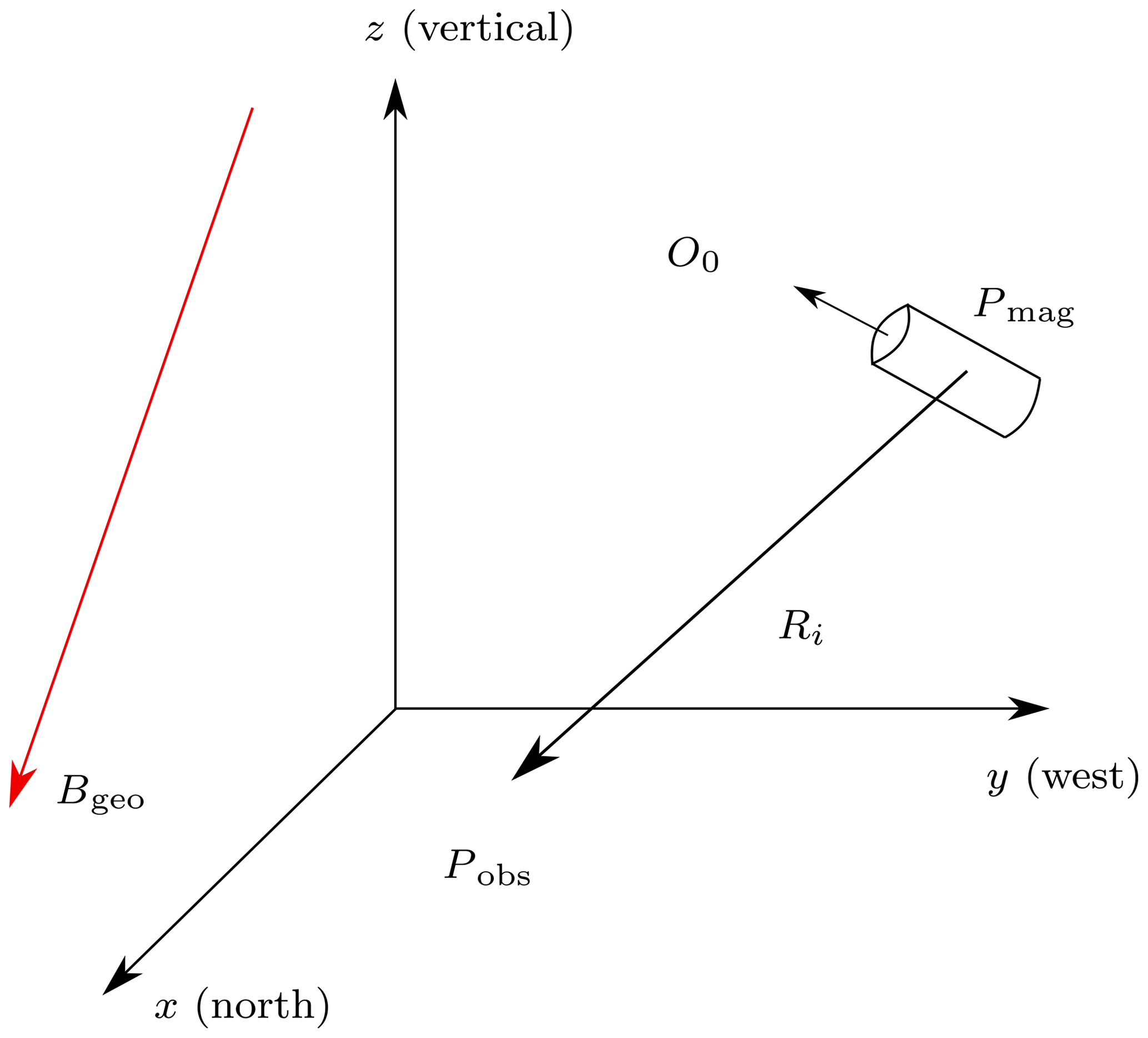
Figure 1Localization scenario of a permanent magnet; the reference coordinate system is depicted. The geomagnetic field Bgeo is interfering.
In the proposed simulations, B of the magnet was superimposed by the geomagnetic flux density Bgeo Erlangen, Germany, with the x- (north), y- (west), and z- (vertical) components approx. µT resulting in an absolute value of 48.8 µT with reference to NOAA (2020) (Fig. 1). All considerations in this paper are based on this reference coordinate system.
3.1 Sensor setup and localization method
To estimate position and orientation errors, our previous localization setup (Zeising et al., 2020b) was used. Three identical, stable and elliptical rings (40 cm × 33 cm) were assumed with four magnetic sensors mounted on each ring (Fig. 2). The distance between one ring to another was 10 cm. The length and diameter of the permanent magnet were both 10 mm. The magnetization of the magnet M0 was set to 1150 kA/m along the longitudinal axis of the magnet, corresponding to grade N52 neodymium-iron-boron (NdFeB).
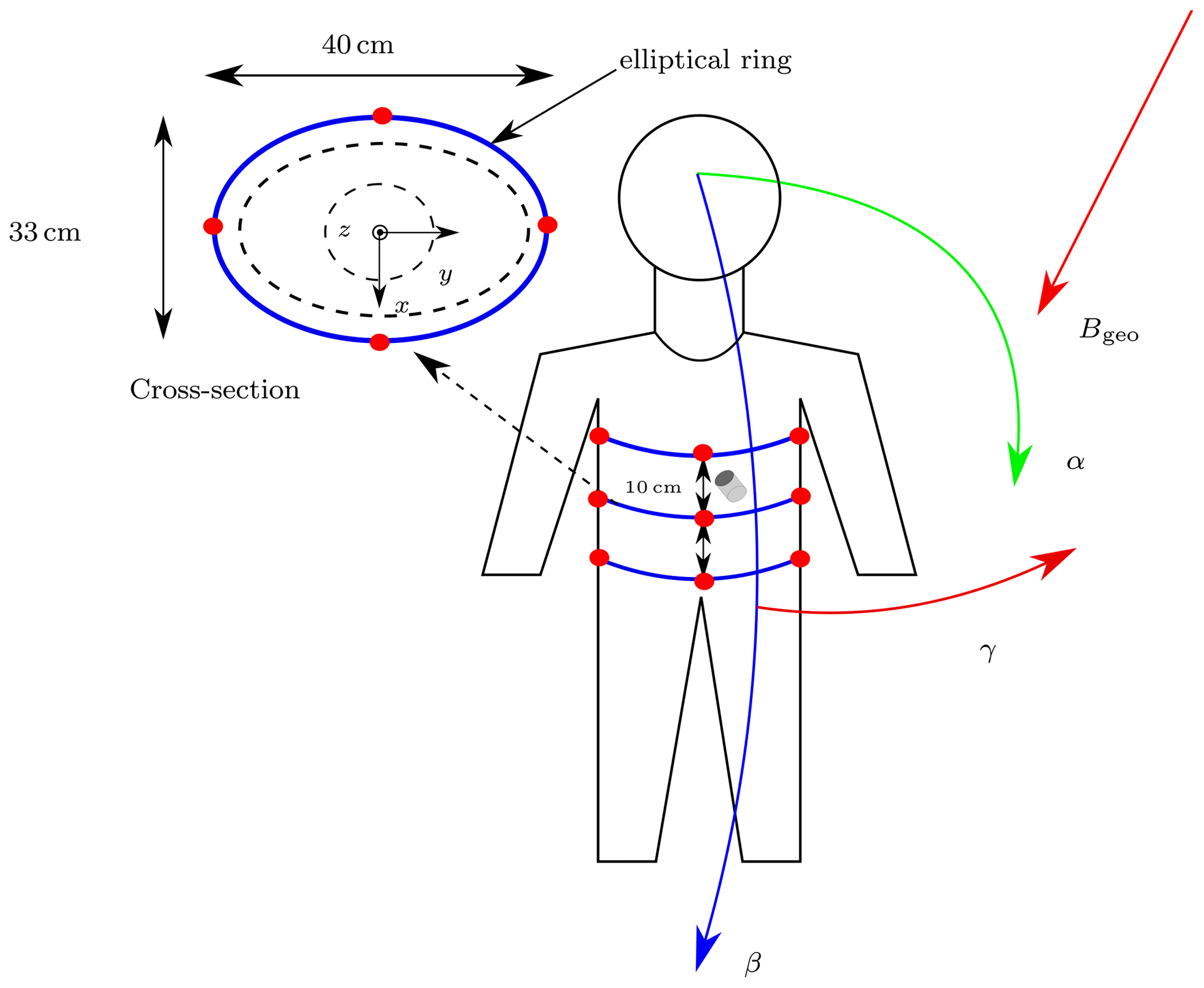
Figure 2Initial orientation of a subject. Reference coordinate system for the localization is shown, with its origin in the center of the middle ring. Sensors are represented by red dots. The cross-section of the middle sensor ring is shown on the left side.
The localization setup was simulated in COMSOL Multiphysics®. Figure 3 depicts the simulation setup for the proposed differential localization method. As computational domain, a sphere with radius 800 mm, filled with air, was set around the sensor setup. As boundary condition of the computational domain, magnetic insulation () was applied. The size of the computational domain was determined by convergence tests with respect to the position and orientation errors as well as the magnetic field distribution (Zeising et al., 2020c). The given radius was found to be sufficiently large to avoid distortions as arose in a previous study (Zeising et al., 2020a).

Figure 3Proposed simulation setup using COMSOL Multiphysics. A sphere as computational domain was set around the localization setup. Sensors and cylindrical magnet are highlighted in red and blue, respectively.
In the following, and B indicate the measured and analytical magnetic flux density, respectively.
3.1.1 Absolute method
To estimate the position and orientation of the magnet, for each sensor, the three respective components of the measured were subtracted from those of the analytical Bi leading to three non-linear equations per sensor. Thus, a 36×6 equation system was derived, which was solved by minimizing the error function ϵ
by applying the Levenberg-Marquardt (LM) algorithm in MATLAB based on the work of Levenberg (1944) and Marquardt (1963). The components of the starting vector of the LM algorithm were set to zero.
3.1.2 Differential method
The proposed differential method is derived from the well-established approach for common-mode rejection in electromagnetic compatibility. For the differential method, the sensors were divided into sensor pairs, each consisting of two opposite sensors (e.g. sensors 1, 2 and 3, 4 in Fig. 4). The two measured values of these pairs were vectorially subtracted before the LM algorithm was applied. In the simulations, it was assumed that the coordinate systems of the individual sensors had the same orientation as the reference coordinate system. This means that sensors, corresponding to a pair, are aligned in such a way that their normal vectors have the same direction and no rotation of the sensors concerning is conducted during the localization process.
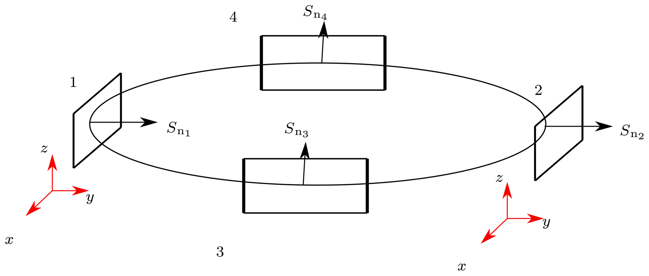
Figure 4Representative sensor ring. The normal vectors Sn of two opposite sensors are shown. The coordinate systems of two opposite sensors are highlighted in red. The two sensor pairs consisting of sensors 1, 2 and 3, 4, respectively, have identical oriented normal vectors.
Consequently, the three components of Bgeo were equal at two sensors and, by applying the differential method, canceled out. As each sensor yields three non-linear equations, subtracting the equations from those of the respective opposite sensor reduces the dimension of the equation system by a factor of two. This operation is valid because the system is over-determined.
3.1.3 Position and orientation errors
The final solution vector x was used to calculate the position ϵP and orientation ϵO errors which are defined as
where ϵP is the distance from the true position Pmag of the magnet to the estimated position . Moreover, ϵO is the angle between O0 of the magnet and the estimated .
3.2 Comparison between absolute and differential method
To evaluate the localization performance, the position of the magnet was set to mm. To investigate the robustness of the absolute and differential methods, the complete setup was rotated around the x-, y- and z-axes of the reference coordinate system by the corresponding angles α, β and γ (Fig. 2). For the initial orientation the geomagnetic flux density according to Sect. 2 was considered. To cover various body positions and orientations in daily life, the rotation angles were varied from −90 to 90∘ in steps of 15∘ (while the other two angles were 0∘) leading to components of Bgeo, which are dependent on the rotation angles. Furthermore, four different orientations (Table 1) of the magnet were applied on each rotation case, leading to 12 different localization scenarios.
Table 1The four different magnet orientations, applied on each of the three different rotations.

First, for each scenario, the mean values of the position ϵP and orientation ϵO errors concerning the respective rotation angle for the ith orientation of the magnet were determined, according to
where i denotes the four orientations of the magnet and j is the variable for the respective rotation angle.
Subsequently, the mean and SD values of the position and orientation errors for the four applied orientation cases were calculated for each of the three rotations according to
3.3 Evaluation of the impact of sensor non-idealities on the differential method
The proposed differential static magnetic localization method was evaluated under ideal conditions (sensor properties like gain were not considered). Therefore, sensors which are equally aligned would measure the exact same magnetic flux density. When the differential method is applied on a real localization system, these non-idealities would lead to fluctuation in the measured flux density, which is not equal for different sensors. To investigate the impact of such non-idealities of the sensors and their calibration on the localization accuracy of the proposed differential method, uniformly distributed random values for with absolute maximum values ranging from 30 to 5000 nT for the x-, y- and z-components of the measured values at each sensor were added and the evaluation procedure was the same as described in Sect. 3.2.
4.1 Comparison of absolute and differential static magnetic localization method
In Fig. 5, the respective mean values and standard deviation (SD) of ϵP and ϵO for the three different rotations of the whole localization system are shown for the absolute and differential method in logarithmic scale.

Figure 5Comparison of the position and orientation errors by applying the differential and absolute static magnetic localization method on the proposed sensor setup. The y-axis shows the errors in logarithmic scale and the x the three different rotations of the whole sensor setup, respectively. By applying the differential method, the position and orientation errors were reduced by three orders of magnitude and the errors were constant for the different rotations.
The first essential finding of this study is that the position and orientation errors were reduced from at least 20 mm and 10∘, respectively, with the absolute method to less than 0.1 mm and 0.1∘, respectively, with the differential method. Second, the localization accuracy was not dependent on the different rotations for the differential method, which is especially required for a wearable localization system. Furthermore, the SD of the position and orientation errors were reduced by two orders of magnitude. Therefore, the impact of the magnet orientation on the localization performance was significantly reduced by applying the differential method.
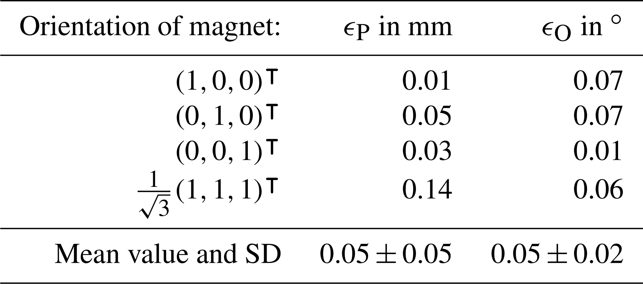
Table 2 shows the ϵP and ϵO for the four different orientations of the magnet after applying the differential method. The position error was greatest when the magnet was in -orientation with 0.14 mm, whereas it was smallest for x-orientation with 0.01 mm. The mean value and SD for the position error were 0.05 ± 0.05 mm. For all four applied orientations of the magnet, the orientation errors were not greater than 0.07∘. The orientation error was the smallest with 0.01∘ when the magnet was in z-orientation. The mean value and SD for the orientation error were 0.05 ± 0.02∘.
By applying the absolute method, the SD values revealed that the variation of the orientation of the magnet had a significant impact on the position and orientation errors for the respective rotations. This was due to the large difference of 64.7 µT in amplitude between the x- and z-components of Bgeo, compared with the differences for the x- and y-components and y- and z-components which are 21.4 and 45.7 µT, respectively. The errors were smallest when the setup was rotated around the body axis γ, whereas they were greatest for a rotation around β (i.e. in forward/backward direction). This trend was also observed in the SD values.
Table 2Position ϵP and orientation ϵO errors and their mean value and standard deviation (SD) for the differential method for the four different orientations of the magnet.
These results, especially the SD of the errors, demonstrate that the orientation vector O0 of the magnet affects the localization process. Compared with the results of the absolute method, the impact of O0 was significantly reduced by applying the differential method and the mean position and orientation errors were reduced by three orders of magnitude.
4.2 Results for applying random values on the measurements of the differential method
Figure 6 shows the mean values and SD for the position and orientation errors after applying random magnetic flux densities on the three components of the measured . Here, the y-axis is in logarithmic scale and the x-axis in linear scale. As can be seen, the errors increased with higher random values in a close-to-exponential way. For random values up to 500 nT, the position and orientation errors were less than 1 mm and 1∘, respectively. For a random value of 5000 nT, the position and orientation errors reached approximately 10 mm and 4∘, respectively.
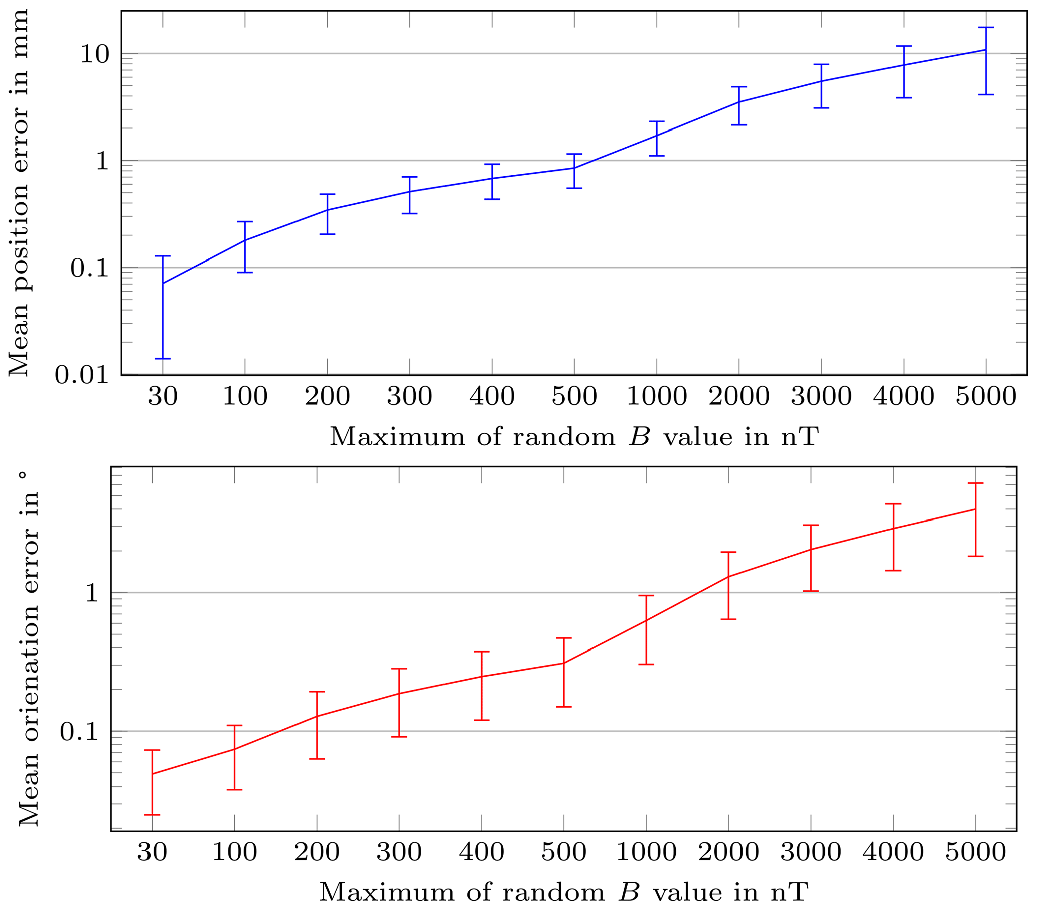
Figure 6Mean position and orientation errors and SD for different applied random magnetic flux densities on the measured values.
4.3 Comparison with existing methods
Shao et al. (2019) proposed a method for preventing interference caused by the geomagnetic flux density. Here, two additional sensors were added to the localization system and mounted on the chest and back of a patient. By subtracting the measured values at the additional sensors from those of the sensor array, geomagnetic compensation was achieved. In their experiments, the mean position and orientation errors were 10 mm and 12∘, respectively. However, additional sensors that are not part of the localization setup make the system more prone to sensor misalignment and displacement of the sensors because they are mounted on the chest and back of a subject. Thus, the relative position regarding the coordinate system of the sensor array is not stable, and the orientation of the additional sensors can vary significantly (e.g. during breathing) from those of the sensor array. In addition, in their study, the orientation error varied significantly for several degrees for different rotations of the localization system.
Another dynamic approach for localization of capsule endoscopes with geomagnetic compensation was proposed by Dai et al. (2019). A magnetic sensor array with a mounted inertial sensor was established to localize a permanent magnet. The localization system was rotated during the localization procedure and due to the additional measurements of the inertial sensor, the components of the geomagnetic flux density were separated for each rotation from the measured magnetic flux density generated by the permanent magnet. In their study, mean position and orientation errors of 3.89 mm and 5.5∘, respectively, were experimentally achieved. A stability evaluation, in which the whole system was rotated while the permanent magnet position was fixed, of their proposed dynamic geomagnetic compensation method showed that a localization accuracy of approx. ±3 mm within a time period of 90 s was reached. They declared that the localization error would increase over time due to the drift error of the inertial sensor. By considering the average time interval of approx. 8 h of a diagnosis procedure with WCE, this method should be tested within a longer time interval.
Without considering fluctuations in measured values due to sensor non-idealities, the mean position and orientation errors of the differential method proposed in this simulation-based study were significantly better with less than 0.1 mm and 0.1∘, respectively. For a wearable localization system for the WCE application, it is essential that the localization performance is invariant from the rotation of the system. Our results revealed that the localization performance is not dependent on time and the rotation of the localization system in case that sensors corresponding to a pair are equally aligned. This highlights that the proposed system is a more favorable choice than state-of-the-art geomagnetic compensation methods for the localization of capsule endoscopes.
By applying random magnetic flux densities on the three components of the measured flux density, the position and orientation errors increased. For a random value of 500 nT, the position and orientation errors were still below 1 mm and 1∘. For a random value of 5000 nT, the position and orientation errors were approx. 10 mm and 4∘, respectively. Therefore, our proposed differential static magnetic localization method is competitive with the methods proposed by Shao et al. (2019) and Dai et al. (2019) also for non-ideal conditions. However, it should be noted that we proposed simulation-based results, whereas Shao et al. (2019) and Dai et al. (2019) experimental results.
4.4 Limitations and challenges of the proposed differential method
To ensure highly accurate and rotation-invariant localization of capsule endoscopes with the proposed differential static magnetic localization method, the sensor rings need to be mechanically stable to minimize possible displacement and misalignment of the magnetic sensors. Moreover, the sensor calibration for hard- and soft-magnetic distortion must be optimized in order to keep the fluctuation in the measured magnetic flux density with respect to the orientation of the localization system as small as possible.
This paper introduced an innovative differential localization method for WCE to make the localization robust against interference of the geomagnetic flux density. Under the assumptions made, the geomagnetic flux density had no impact on the proposed method. Compared to the absolute magnetic localization method, the position and orientation errors were reduced by three orders of magnitude to less than 0.1 mm and 0.1∘ under ideal conditions. When the root-mean-square noise of state-of-the-art magnetometers was considered, the position and orientation errors were below 1 mm and 1∘, respectively. The simulation-based results of this study showed that the proposed differential method is competitive with state-of-the-art geomagnetic compensation methods, even under non-ideal conditions. Furthermore, the impact of the orientation of the magnet was significantly reduced as suggested by the values of the standard deviation concerning the four different orientations of the magnet. For a realization of the proposed method, the sensor rings should be mechanically stable and sensors corresponding to a pair aligned in order to ensure appropriate localization accuracy with respect to the rotation of the system relative to the geomagnetic flux density. The impact of misalignment and displacement of sensors as well as the impact of ferromagnetic material on the proposed method requires further investigations. Moreover, the sensor calibration for hard- and soft-magnetic distortion must be optimized to achieve accurate localization with the proposed differential method. In the future, the localization system will be tested by means of experimental measurements.
The simulation data and MATLAB-code are available from the corresponding author upon request.
DA, GF and JK initiated the research project. SZ developed the method. SZ and AT carried out the simulations and interpreted the results. All authors were involved in writing and reviewing the manuscript.
The authors declare that they have no conflict of interest.
The responsibility for the content of this publication is with the authors.
Publisher's note: Copernicus Publications remains neutral with regard to jurisdictional claims in published maps and institutional affiliations.
This article is part of the special issue “Kleinheubacher Berichte 2020”.
This paper was edited by Lars Ole Fichte and reviewed by Georgiana Rosu and one anonymous referee.
Bianchi, F., Masaracchia, A., Shojaei Barjuei, E., Menciassi, A., Arezzo, A., Koulaouzidis, A., Stoyanov, D., Dario, P., and Ciuti, G.: Localization strategies for robotic endoscopic capsules: a review, Exp. Rev. Med. Devic., 16, 381–403, https://doi.org/10.1080/17434440.2019.1608182, 2019. a
Dai, H., Hu, C., Su, S., Lin, M., and Song, S.: Geomagnetic Compensation for the Rotating of Magnetometer Array During Magnetic Tracking, IEEE T. Instrum. Meas., 68, 3379–3386, https://doi.org/10.1109/tim.2018.2875965, 2019. a, b, c, d, e
Glaser, R.: Biophysics, 1st Edn., Springer-Verlag Berlin Heidelberg, 2000. a
Hu, C., Ren, Y., You, X., Yang, W., Song, S., Xiang, S., He, X., Zhang, Z., and Meng, M. Q.-H.: Locating Intra-Body Capsule Object by Three-Magnet Sensing System, IEEE Sens. J., 16, 5167–5176, https://doi.org/10.1109/JSEN.2016.2558198, 2016. a, b
Iddan, G., Meron, G., Glukhovsky, A., and Swain, P.: Wireless capsule endoscopy, Nature, 405, 417, https://doi.org/10.1038/35013140, 2000. a
Jackson, J. D.: Classical electrodynamics, 1st Edn., John Wiley & Sons, New York, United States, 1962. a
Kanaan, M. and Cil, M.: Cramer-Rao Lower Bounds for Magnetic Localization of a Wireless Capsule Endoscope based on the Magnetic Dipole Model, 2019 IEEE 30th International Symposium on Personal, Indoor and Mobile Radio Communications (PIMRC Workshops), 1–5, https://doi.org/10.1109/PIMRCW.2019.8880827, 2019. a
Levenberg, K.: A Method for the Solution of Certain Non-linear Problems in Least Squares, Q. Appl. Math., 2, 164–168, 1944. a
Marquardt, D. W.: An Algorithm for Least-Squares Estimation of Nonlinear Parameters, J. Soc. Ind. Appl. Math., 11, 431–441, 1963. a
Mateen, H., Basar, R., Ahmed, A. U., and Ahmad, M. Y.: Localization of Wireless Capsule Endoscope: A Systematic Review, IEEE Sens. J., 17, 1197–1206, https://doi.org/10.1109/JSEN.2016.2645945, 2017. a
NOAA: National Centers for Environmental Information, available at: https://www.ngdc.noaa.gov/, last access: 10 July 2020. a
Pham, D. M. and Aziz, S. M.: A real-time localization system for an endoscopic capsule using magnetic sensors, Sensors (Basel, Switzerland), 14, 20910–20929, https://doi.org/10.3390/s141120910, 2014. a, b
Shao, G., Tang, Y., Tang, L., Dai, Q., and Guo, Y.-X.: A Novel Passive Magnetic Localization Wearable System for Wireless Capsule Endoscopy, IEEE Sens. J., 19, 3462–3472, https://doi.org/10.1109/JSEN.2019.2894386, 2019. a, b, c, d, e, f
Swain, C., Gong, F., and Mills, T.: Wireless transmission of a colour television moving image from the stomach using a miniature CCD camera, light source and microwave transmitter, Gastrointest. Endosc., 45, https://doi.org/10.1016/S0016-5107(97)80063-6, 1997. a
Wang, M., Shi, Q., Song, S., Hu, C., and Meng, M. Q.-H.: A Novel Relative Position Estimation Method for Capsule Robot Moving in Gastrointestinal Tract, Sensors (Basel, Switzerland), 19, 2746, https://doi.org/10.3390/s19122746, 2019. a
Zeising, S., Anzai, D., Thalmayer, A., Fischer, G., and Kirchner, J.: Novel Differential Magnetic Localization Method for Capsule Endoscopy to Prevent Interference Caused by the Geomagnetic Field, in: Kleinheubach Conference, Book of Abstracts, in press, 2020a. a, b
Zeising, S., Anzai, D., Thalmayer, A., Fischer, G., and Kirchner, J.: Evaluation of the Impact of Static Interference on an Empirical Data Based Static Magnetic Localization Setup for Capsule Endoscopy, Current Directions in Biomedical Engineering, 6, 20203017, https://doi.org/10.1515/cdbme-2020-3017, 2020b. a, b
Zeising, S., Ararat, K., Thalmayer, A., Anzai, D., Fischer, G., and Kirchner, J.: Performance Optimization of a Differential Method for Localization of Capsule Endoscopes, Eng. Proc. 2, 31, https://doi.org/10.3390/ecsa-7-08271, 2020c. a, b